A Novel Improved Performance of Direct Power Control of
Unbalanced AC Source
1
Gangavarapu Samson;
2Dr.P.Ramesh M. Tech , P.hd &
3D.Prasad M.Tech
1
PG Scholar , Department of Electrical & Electronics Engineering,PACE Institute of Technology& Sciences,
Ongole, AP, India.
2
Professor & Head of Electrical & Electronics Engineering Department,PACE Institute of Technology&
Sciences, Ongole, AP, India.
3
Associate Professor in the Department of Electrical & Electronics Engineering, PACE Institute of Technology &
Sciences, Ongole, AP, India
Abstract—
Three-phase dc–ac power converters suffer
from
power
oscillation
and
overcurrent
problems in case of the unbal-anced ac source
voltage voltage that can be caused by
grid/generator faults. Existing solutions to
handle these problems are properly selecting
and controlling the positive- and
negative-sequence currents. In this paper, a new series of
control strategies which utilize the zero-
sequence components are proposed to enhance
the power control ability under this adverse
condition. It is concluded that by introducing
proper zero-sequence current controls and
corresponding circuit configurations, the power
converter can enable more flexi-ble control
targets, achieving better performances in
thedelivered power and the load current when
suffering from the unbalanced ac voltage.
Index Terms—
Control strategy; dc–ac converter;
fault tolerance;
unbalanced ac source
I. INTRODUCTION
Electric power flow through an alternating current transmission line is a function of the line impedance, the magnitudes of the sending-end and receiving-end voltages, and the phase angle between these voltages. Essentially, the power flow is dependent on the voltage across the line impedance. Electricity market deregulation, together with growing economic, environmental, and social concerns, has increased the difficulty to burn fossil fuels, and to obtain new licenses to build transmission lines (rights-of-way) and high power facilities. This situation started the growth of decentralized electricity generation. renewable energy generation, motor drives, power quality,and
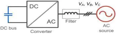
microgrid, etc., the three-phase dc–ac converters are critical components as the power flow interface of dc and ac electrical systems [1], [2]. As shown in Fig. 1, a dc–ac voltage source converter with a corresponding filter is typically used to convert the energy between the dc bus and the three-phase ac sources, which could be the power grid, generation units, or the electric machines depending on the applications and controls [3]–[5].
Since the power electronics are getting so widely used and becoming essential in the energy conversion technology, the failures or shutting down of these backbone dc–ac converters may result in serious problems and cost. It is becoming a need in many applications that the power converters should be reli-able to withstand some faults or disturbances in order to ensure certain availability of the energy supply [6]–[13]. A good ex-ample can be seen in the wind power application, where both the total installed capacity and individual capacity of the power conversion system are relatively high. The sudden disconnection
Fig. 1. Typical dc–ac power converter
control methods seem to be still not satisfactory: either distorted load currents or power oscillations will be presented, and thereby not only the ac source but also the power converter will be further stressed accompanying with the costly design considerations.
Fig.2. Phasor diagram definitions for the voltage dips in the ac source of Fig. 1. VA, VB , and VC means the voltage
of three phases in the ac source.
This paper targets to understand and improve the power con-trol limits of a typical three-phase dc–ac converter system under the unbalanced ac source. A new series of control strategies which utilizes the zero-sequence components are then proposed to enhance the power control ability under this adverse condi-tion. Besides the grid integration, the proposed control methods have the potential to be applied under other applications like the motor/generator connections or microgrids, where the un-balanced ac voltage is likely to be presented; therefore, the basic principle and feasibility are mainly focused.
II. LIMITS OF A TYPICAL THREE-WIRE CONVERTER SYSTEM
In order to analyze the controllability and the performance of the power electronics converter under an adverse ac source, a severe unbalanced ac voltage is first defined as a case study in this paper. As shown in Fig. 3, the phasor diagram of the three-phase distorted ac voltage are indicated, it is assumed that the type B fault happens with the significant voltage dip on phase A of the ac source. Also, there are many other types of voltage faults which have been defined as type A–F in [22].
According to [2] and [19], any distorted three-phase voltage can be expressed by the sum of components in the positive se-quence, negative sequence, and zero sequence. For simplicity of analysis, only the components with the fundamental frequency are considered in this paper, however, it is also possible to extend the analysis to higher order harmonics. The distorted three-phase ac source voltage in Fig. 2. can be represented by.
240
,
cos
120
cos
cos
t
V
v
t
V
v
t
V
v
m c m b m a
Fig.3A three-phase system is shown in Fig 1. In a special case all impedances are identical
Za = Zb = Zc = Z .
Such a load is called a balanced load and is described by equations
I
V
Z
I
V
Z
I
V
Z
a
a b
b c
c
Using KCL, we have
I
I
I
I
Z
V
V
V
n
a
b
c
a
b
c1
(1) Where
0.2 3 j 2 1 2 3 j 2 1 1 V 240 sin j 240 cos 120 sin j 120 cos 1 V e e 1 V V V V m m 240 j 120 j m c b a
Setting the above result into (1), we obtain
I
n
0
(2)In
Ia Za
Va
Ic Zc
Vc
Ib Zb
Fig. 4. Typical three-phase three-wire 2L-voltage source converter
A typically used three-phase three-wire two-level voltage source dc–ac converter is chosen and basically designed, as shown in Fig. 4 and Table I, where the converter configuration and the parameters are indicated, respectively. It is noted that the three-phase ac source is represented here by three windings with a common neutral point, which can be the windings of an electric machine or a transformer. Because there are only three wires and a common neutral point in the windings of the ac source, the currents flowing in the three phases do not contain zero-sequence components. . As a result, the three-phase load current controlled by the converter can be written as
IC = I+ + I−. (3)
Three-phase systems calculations
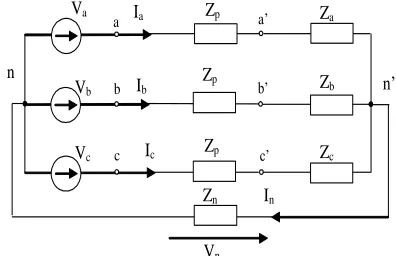
When the three phases of the load are not identical, an unbalanced system is produced. An unbalanced Y-connected system is shown in Fig The system of Fig.contains perfectly conducting wires connecting the source to the load. Now we consider a more realistic case where the wires are represented by impedances Zp and the
neutral wire connecting n and n’ is represented by impedance Zn ( see Fig.5). Using the node n as the datum,
we express the currents Ia, Ib, Ic and In in terms of the node
voltage Vn
V
V
Z
Z
V
Z
Z
V
Z
Z
Z
Z
Z
Z
Z
Z
Z
n
a
a p
b
b p
c
c p
n a p b p c p
1
1
1
1
A. Elimination of the Negative-Sequence Current
In most of the grid integration applications, there are strict grid codes to regulate the behavior of the grid connected con-verters. The negative-sequence current which always results in the unbalanced load current may be unacceptable from the point view of a TSO [13]. Therefore, extra two control targets which aim to eliminate the negative-sequence current can be added as
id −
= 0 iq−= 0.
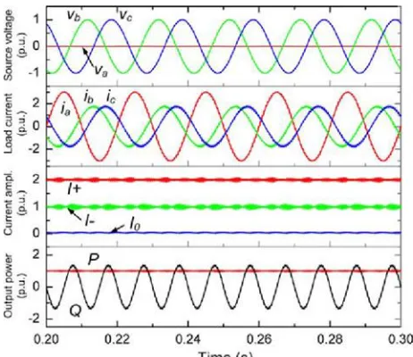
When applying the current references in (12) and (13), the ac source voltage, load current, sequence current amplitude, and the instantaneous power delivered by the converter are shown in Fig. 5. The simulation is based on the parameters predefined
dipping to zero. The average active power reference Pre f
for the converter is set as 1 p.u. and the reactive power reference Qre f is set as 0.It can be seen from Fig. 5 that
with the extra control targets in (11), there is no zero-sequence nor negative-zero-sequence com-ponents in the load
current, i.e., the currents among the three phases of
converter are symmetrical under the given unbalanced ac source condition.
The current amplitude in different sequences and the deliv-ered active/reactive power with relation to the voltage amplitude of the dipping phase VA are shown in
Fig. 6(a) and (b), respec-tively. It is noted that only the positive-sequence current is gen-erated by the converter, and there is up to ±0.5 p.u. oscillations both in the active and reactive power when VA dips to zero. The significant
fluctuation of the active power would result in the voltage fluctuation of the dc bus [16]–[19], compromising not only the THD but also the reliability performances of the converter according to [23].
c b a
Vn
Zn
c’ a’
b’
Zp
Zp
Zp
In
n’ n
Ia Za
Va
Ic Zc
Vc
Ib Zb
Fig.5. Simulation of the converter with no negative-sequence current control (three-phase three-wire converter, Pr e f = 1 p.u., Qr e f = 0 p.u., Id− = 0 p.u., Iq − =
0 p.u., VA=0 p.u., I+, I−, and I0means the amplitude of
the currentin the positive, negative, and zero sequences, respectively).
B. Elimination of the Active Power Oscillation
In order to overcome the disadvantage of the active power oscillation under the unbalanced ac source, another two extra control targets which aim to cancel the oscillation items in the instantaneous active power can be used to replace as
P3φ c 2 =Pc 2 = 0
P3φ s2 = Ps2 = 0.
It can be seen that the active power oscillation at twice of the fundamental frequency can be eliminated However, the disadvantage of this control strategy is also significant: first, the converter has to deliver up to 3 p.u. load current in the faulty phase which is much larger than the currents in other two normal phases—this large current may cause over loading of the system and result in failures. Moreover, significant fluctuation of the reactive power will be presented compared to the control strategy in Fig. 5. In case of the grid-connected application, this significant reactive power oscillation may cause grid voltage fluctuation, which is unpreferred especially with weak grid and grid faults.
Fig. 6. Simulation of the converter control with no active power oscillation (three-phase three-wire converter, Pr e f
= 1 p.u., Qr e f = 0 p.u., Ps2 = 0 p.u., Pc2=0 p.u., VA= 0
p.u. I+, I−, and I0means the amplitude of the current in
the positive, negative, and zero sequences, respectively.
.
III. CONVERTER SYSTEM WITH THE ZERO-SEQUENCE CURRENT PATH
As can be concluded, in the typical phase three-wire converter structure, four control freedoms for the load current seem to be not enough to achieve satisfactory performances under the unbalanced ac source. (No matter what combinations of control targets are used, either significant power oscillation or overloaded/distorted current will be presented.) Therefore, more current control freedoms are needed in order to improve the control performance under the unbalanced ac source conditions.
Another series of the converter structure are shown as indi-cated as the four-wire system in Fig. 9(a) and the six-wire system in Fig. 9(b). Compared to the three-six-wire converter structure, these types of converters introduce the zero-sequence current path [24]–[26], which may enable extra current control free-doms to achieve better power control performances. It is noted that in the grid-connected application, the zero-sequence current is not injected into the grid but trapped in the typically used d-Y
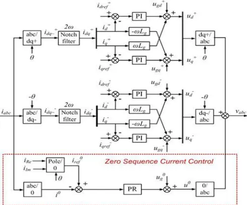
Fig. 10. Control structure for the converter system with the zero-sequence current.
A. Elimination of Both the Active and Reactive Power oscillation
The current amplitude in different sequences, as well as the delivered active/reactive power with relation to the voltage am-plitude on the dipping phase is shown in Fig. , re-spectively. It is noted that the converter has to deliver positive-, negative-, and zero-sequence currents to achieve this control strategy. And the zero sequence current is controlled as zero when the voltage dip is at 1.0 p.u.
Fig.15. Configurations of the experimental setup
a larger dc capacitance or a rectifier with controllability of
the midpoint potential is preferred for the four-wire converter struc-ture shown in Fig. 9(a). However, there is no such problem in the six-wire converter structure shown in Fig. 9(b).Moreover, according to (35) and (42), the reference current for the zero sequence is inverse proportional with the zero sequence voltage v0 . The
effectiveness of the proposed control methods should rely on the amount of v0 in the unbalanced ac source. In some
cases of two-phase or three-phase faults with no or very small v0 , the performance of the proposed control
strategies will be different, and new control methods which do not utilize the power from the zero sequence are needed. It is also noted that the dynamical performance and the sequence-extracting algorithm are also critical considerations for the control methods under the unbalanced ac source, either for the transient condition (e.g., LVRT) or the stability during the steady-state operation, however, they are out of the scope of this paper
IV. EXPERIMENTAL RESULTS
The control results by different converter structures and con-trol strategies are validated on a downscale dc–ac converter. As shown in Fig. 15, the circuit configurations and setup photo are both illustrated. A three-phase two-level converter with cor-responding LCL filter is used to interconnect two dc voltage sources and a programmable three-phase ac voltage source. The detail parameters of the experimental setup are shown in Ta-ble III. It is noted that the converter is controlled to operate at the inverter mode, where the active power is flowing from the dc source to the ac source. By opening and closing a switch shown in Fig. 15(a), the converter can be shifted between the typical three-wire system and four-wire system with the zero-sequence current path. The amplitude of the phase A voltage in the pro-grammable ac source is adjusted to 0.1 p.u. (22 Vrm s ) in order to establish an
adverse unbalanced condition.
After enabling the zero current path and proposed controls, the performances of the given converter are
shown again in Fig. 17, where the same conditions and two control strategies mentioned in Figs. 11 and 13 are applied, respectively. It can be seen that the experimental results also agree well with the simulation results, where the power oscillations are much more reduced or even totally cancelled; meanwhile, the current stress in the faulty phase is significantly relieved. These critical
perfor-mances are hard to be achieved by a single three-wire converter structure using existing control strategies.
respectively, to deliver the inductive and capacitive reactive power with phase A voltage dipping to 0.5 p.u. It can be seen that the advantages of the smaller/eliminated power oscillation and the relieved current loading in the aulty phases are still maintained. It is noted that the power delivering under the unbalanced AC source should give priority to the current limits of the power devices. This topic has been well discussed in the existing control methods based on the three-wire structure [30], and it is also an important consideration in the proposed control methods which utilize the zero-sequence components. In the experiment, the maximum reactive power is limited by the maximum current loading, which all achieve 1 p.u. in Figs..
V. CONCLUSION
In a typical three-phase three-wire converter structure, there are four current control freedoms, and it may be not enough to achieve satisfactory performances under the unbalanced ac source, because either significantly the oscillated power or the overloaded current will be presented.
In the three-phase converter structure with the zero sequence current path, there are six current control freedoms. The extra two control freedoms coming from the zero sequence current canbe utilized to extend the controllability of the converter and im-prove the control performance under the unbalanced ac source. By the proposed control strategies, it is possible to totally can-cel the oscillation in both the active and the reactive power, or reduced the oscillation amplitude in the reactive power. Mean-while, the current amplitude of the faulty phase is significantly relieved without further increasing the current amplitude in the normal phases. The advantage and features of the proposed controls can be still maintained under various conditions when delivering the reactive power. The analysis and proposed control methods are well agreed by experimental validations.
REFERENCES
[1]F. Blaabjerg, M. Liserre, and K. Ma, ―Power electronics converters for wind turbine systems,‖
IEEE Trans. Ind. Appl., vol. 48, no. 2, pp. 708– 719, Mar./Apr. 2012.
[2]R. Teodorescu, M. Liserre, and P. Rodriguez, Grid Converters for Pho-tovoltaic and Wind Power Systems. New York, NY, USA: Wiley-IEEE,2011.
[3]J. Rocabert, G. M. S. Azevedo, A. Luna, J. M. Guerrero, J. I. Candela, and
P. Rodriguez, ―Intelligent connection agent for three-phase grid-connected microgrids,‖ IEEE Trans. Power Electron, vol. 26, no. 10, pp. 2993–3005, Oct. 2011.
[4]J. W. Kolar and T. Friedli, ―The essence of three-phase PFC rectifier systems—Part I,‖ IEEE Trans. Power Electron., vol. 28, no. 1, pp. 176– 198, Jan. 2013.
[5]J. Hu, L. Shang, Y. He, and Z. Z. Zhu, ―Direct active and reactive power regulation of grid-connected dc/ac converters using sliding mode control approach,‖ IEEE Trans. Power Electron., vol. 26, no. 1, pp. 210–222, Jan. 2011.
[6]C. Wessels, F. Gebhardt, and F. W. Fuchs, ―Fault ride-through of a DFIG wind turbine using a dynamic voltage restorer during symmetrical and asymmetrical grid faults,‖ IEEE Trans. Power Electron., vol. 26, no. 3, pp. 807–815, Mar. 2011. [7]F. Aghili, ―Fault-tolerant torque control of BLDC
motors,‖ IEEE Trans.Power Electron., vol. 26, no. 2, pp. 355–363, Feb. 2011
.
[8]Y. Xiangwu, G. Venkataramanan, W. Yang, D. Qing, and Z. Bo, ―Grid-fault tolerant operation of a DFIG wind turbine generator using a pas-sive resistance network,‖ IEEE Trans. Power Electron., vol. 26, no. 10, pp. 2896–2905, Oct. 2011.
[9]B. A. Welchko, T. A. Lipo, T. M. Jahns, and S. E. Schulz, ―Fault tolerant three-phase AC motor drive topologies: A comparison of features, cost, and limitations,‖ IEEE Trans. Power Electron., vol. 19, no. 4, pp. 1108– 1116, Jul. 2004.
electronics and reliability in renewable energy systems,‖ in Proc. IEEE Int. Symp. Ind. Electron., May 2012, pp. 19–30.
[11]Y. Song and B. Wang, ―Survey on reliability of power electronic systems,‖ IEEE Trans. Power Electron., vol. 28, no. 1, pp. 591–604, Jan. 2013. [12]M. Altin, O. Goksu, R. Teodorescu, P. Rodriguez, B.
Bak-Jensen, and
L.Helle, ―Overview of recent grid codes for wind power integration,‖ in
Proc. 12th Int. Conf. Optim. Elect. Electron. Equip., 2010, pp. 1152–1160.
[13]Grid Code. High and Extra High Voltage, E.ON-netz, Bayreuth, Germany,
Apr. 2006.
[14] P. Rodr´ıguez, A. Luna, R. Munoz˜-Aguilar, I. Etxeberria-Otadui, R. Teodorescu, and F. Blaabjerg, ―A stationary reference frame grid syn-chronization system for three-phase grid-connected power converters un-der adverse grid conditions,‖ IEEE Trans. Power Electron., vol. 27, no. 1,
pp. 99–112, Jan. 2012.
[15]A. J. Roscoe, S. J. Finney, and G. M. Burt, ―Tradeoffs between AC power quality and DC bus ripple for 3-phase 3-wire inverter-connected devices within microgrids,‖ IEEE Trans. Power Electron., vol. 26, no. 3, pp. 674– 688, Mar. 2011
[13] F. Blaabjerg, M. Liserre, and K. Ma, ―Power electronics converters for wind turbine systems,‖
IEEE Trans. Ind. Appl., vol. 48, no. 2, pp. 708– 719, Mar./Apr. 2012.
[14] R. Teodorescu, M. Liserre, and P. Rodriguez,
Grid Converters for Pho-tovoltaic and Wind Power Systems. New York, NY, USA: Wiley-IEEE,2011. [15] J. Rocabert, G. M. S. Azevedo, A. Luna, J. M.
Guerrero, J. I. Candela, and
P. Rodriguez, ―Intelligent connection agent for three-phase grid-connected microgrids,‖ IEEE Trans. Power Electron, vol. 26, no. 10, pp. 2993–3005, Oct. 2011.
[16] J. W. Kolar and T. Friedli, ―The essence of three-phase PFC rectifier systems—Part I,‖ IEEE Trans. Power Electron., vol. 28, no. 1, pp. 176– 198, Jan. 2013.
[17] J. Hu, L. Shang, Y. He, and Z. Z. Zhu, ―Direct active and reactive power regulation of grid-connected dc/ac converters using sliding mode control approach,‖ IEEE Trans. Power Electron., vol. 26, no. 1, pp. 210–222, Jan. 2011.
[18] C. Wessels, F. Gebhardt, and F. W. Fuchs, ―Fault ride-through of a DFIG wind turbine using a dynamic voltage restorer during symmetrical and asymmetrical grid faults,‖ IEEE Trans. Power Electron., vol. 26, no. 3, pp. 807–815, Mar. 2011. [19] F. Aghili, ―Fault-tolerant torque control of
BLDC motors,‖ IEEE Trans. Power Electron., vol. 26, no. 2, pp. 355–363, Feb. 2011
[20] Y. Xiangwu, G. Venkataramanan, W. Yang, D. Qing, and Z. Bo, ―Grid-fault tolerant operation of a DFIG wind turbine generator using a pas-sive resistance network,‖ IEEE Trans. Power Electron., vol. 26, no. 10, pp. 2896–2905, Oct. 2011.
[21] B. A. Welchko, T. A. Lipo, T. M. Jahns, and S. E. Schulz, ―Fault tolerant three-phase AC motor drive topologies: A comparison of features, cost, and limitations,‖ IEEE Trans. Power Electron., vol. 19, no. 4, pp. 1108– 1116, Jul. 2004. F. Blaabjerg, M. Liserre, and
[22] G. Saccomando, J. Svensson, and A. Sannino, ―Improving voltage dis-turbance rejection for variable-speed wind turbines,‖ IEEE Trans. Energy Convers., vol. 17, no. 3, pp. 422–428, Sep. 2002. [23] N. Kaminski and A. Kopta, ―Failure rates of HiPak
Modules due to cosmic rays,‖ ABB Switzerland Ltd., Zurich, Switzerland, ABB Appl. note 5SYA 2042-04, Mar. 2011.
[24] S. Sharma and B. Singh, ―Performance of voltage and frequency controller in isolated wind power generation for a three-phase four-wire system,‖ IEEE Trans. Power Electron., vol. 26, no. 12, pp. 3443–3452, Dec. 2011.
[25]K. Ma, F. Blaabjerg, and M. Liserre, ―Thermal analysis of multilevel grid side converters for 10 mw wind turbines under low voltage ride through,‖ IEEE Trans. Ind. Appl., vol. 49, no. 2, pp. 909–921, Mar./Apr. 2013.
[26]J. Holtz and N. Oikonomou, ―Optimal control of a dual three-level inverter system for medium-voltage drives,‖ IEEE Trans. Ind. Appl., vol. 46, no. 3, pp. 1034–1041, May/Jun. 2010.
[27]E. H. Watanabe, R. M. Stephan, and M. Aredes, ―New concepts of in-stantaneous active and reactive powers in electrical systems with generic loads,‖ IEEE Trans. Power Del., vol. 8, no. 2, pp. 697–703, Apr. 1993.
[29]M. Aredes, J. Hafner, and K. Heumann, ―Three-phase four-wire shunt active filter control strategies,‖ IEEE Trans. Power Electron., vol. 12, no. 2, pp. 311–318, Mar. 1997.
[30]C.-T. Lee, C.-W. Hsu, and P.-T. Cheng, ―A low-voltage ride-through tech-nique for grid-connected converters of distributed energy resources,‖ IEEETrans. Ind. Appl., vol. 47, no. 4, pp. 1821–1832, Jul./Aug. 2011.
D
.Prasad received the B.Tech Degree in EEE from Narasarao peta Engineering College, Narasarao pet, India, in 2005 and M.Tech. Degree in Power Electronics from NIT Calicut in 2008. . Currently working as Associate Professor in the Department of Electrical & Electronics Engineering, PACE Institute of Technology & Sciences, Ongole.Dr.P.Ramesh received B Tech, M tech degree and PhD in Electrical & Electronics Engineering. Currently he is a professor and head of electrical & electronics engineering Department at PACE Institute of Technology& Sciences, Ongole, AP, India. He has published many technical papers in various international journals. He is a corporate member of the Institute of engineers, life member in Indian society of technical education and also member in association of international engineers, society of computer science and information technology. His area of research includes special machines, power and energy, soft computing and power electronics applications.
GANGAVARAPU SAMSON