7
Wireless Sensor Network based Smart Building
Automation System
Y.N.Raghunath babu
ECE Department, Associate Professor Nova Institute of Engineering and Technology;EluruAndhrapradesh,India
Email: [email protected]
Abstract-Benefits of using building automation systems to control lighting include the ability to detect
fire accidents and moisture levels, the ability to monitor and control lighting throughout a large facility, and the ability to minimize peak demand. This paper focuses on the integration of Digital Addressable Lighting Interface (DALI) devices, temperature and moisture sensor circuits for detecting fire accidents and moisture content of a room are gathered and transmitted to the monitoring section using wireless sensor networks.
Keywords:- building automation systems (BAS), DALI, Wireless sensor networks, temperature and
moisture sensors.
1. INTRODUCTION
Present days, people are moving onto automated systems from conventional systems. Conventional systems include analog techniques, whereas the automated systems are of digital type. Similarly when we come across the building automation systems, many different technologies came into existence. But they are complex techniques and consume a lot of power. Here, we tried to build a simple centralized network which is cheaper, less power consuming and simple to control. Existing building automation systems use analog techniques for building automation. They control devices by changing and adjusting the phase of the power supply. The installation cost is high. Also, the power consumed is high. There are some automation techniques which employ digital technology. The digital techniques being employed are quite complex. To reduce the power consumption, cost of installation, we have developed our project to implement a simple automation technique using digital techniques like DALI & wireless sensor networks.
There are certain limitations to this system when we try to control more devices using this system. When we try to integrate more devices together, the whole network can seem complex. Troubleshooting
can also be hard if there is no prior knowledge about the interconnections in the network.
2.TECHNOLOGIES
Building automation is about a simple control system developed to control the various parameters of a building. In our project we are interfacing WSN to achieve this in a better manner than other systems.
2.1 WSN: WSN is the acronym for Wireless
Sensor Networks. A wireless sensor network is a wireless network consisting of spatially distributed autonomous devices using sensors to monitor physical or environmental conditions. We developed this system
using master/slave model, in such a way that the user acts as master and different building nodes act as slaves. Master/slave is a model of communication where one device or process has unidirectional control over one or more other devices. In some systems a master is elected from a group of eligible devices, with the other devices acting in the role of slaves. The home appliances are managed by an IEEE 802.15.4- based wireless sensor network for easy maintenance.
2.1.1Existing system:
8 parameters and the controlling is done automatically
when any of the parameters get abnormal.
2.1.2.Proposed system:
In this system, using Zigbee protocol the building automation like lighting, temperature checking and moisture conditioning is done by using an interface. Here a system with sensors is interfaced with the Microcontroller which is used to monitor the light source, temperature and moisture content of a room. The information about these parameters is gathered and transmitted to the monitoring section using Zigbee wireless communication. Also at the receiver end user can control the system with separate address. So the control data will reach the proper node and after receiving the data the controller will control the devices. A LCD display is used in every section for displaying the status. And the data can even be transmitted to the user or the person who is present to monitor the status of the building using Zigbee protocol.
3.SYSTEM ARCHITECTURE
This system consists of an input, an output and a processor/controller to transform the input into output. The system we developed consists of a microcontroller to perform different operations and to transfer the inputs to outputs. We have used different sensors which form the inputs to the controller. They are LDR, thermistor, humidity sensor. The block diagram of slave section shown in fig1 The outputs we employed are LED and relays in a similar relation to the electrical devices we use in our daily life like lights,
fans, heater, air conditioners etc. LCD display is used to display information individually as per the operation. Zigbee module is employed to transfer and receive the information through wireless communication. User can stay updated about the status of network using his personal computer with front end application which is interfaced with zigbee module using RS-232 cable. The block diagram of master section is shown in fig2.
Fig1 block diagram of slave section.
Fig 2 block diagram of master section.
a) Zigbee:
9 area networks; its aim is the standardization of the
two
lower layers of OSI protocol stack-physical (PHY) and Medium Access Control (MAC) layers. The ZigBee interconnection is shown in fig3. ZigBee is a specification for a suite of high level communication protocols using small, low-power digital radios based on the standard for wireless personal area networks (WPANs), such as wireless headphones connecting with cell phones via short-range radio. The technology defined by the ZigBee specification is intended to be simpler and less expensive than other WPANs, such as Bluetooth. ZigBee is targeted at radio-frequency (RF) applications that require a low data rate, long battery life, and secure networking. A ZigBee node can have three different roles, coordinator and router or end device. ZigBee operates in the industrial, scientific and medical (ISM) radio bands; 868 MHz in Europe, 915 MHz in the USA and Australia, and 2.4 GHz in most jurisdictions worldwide. The technology is intended to be simpler and less expensive than other WPANs such as Bluetooth.
fig3. Zigbee interconnection
b) Thermistor:
Thermistor is used to detect temperature changes and gives high output signal to microcontroller. A thermistor is a type of resistor with resistance inversely proportional to its temperature. Thermistors are widely used as inrush current limiters, temperature sensors, self-resetting over-current protectors, and self-regulating heating elements.
c) Light dependent resistor:
The LDR can be used to detect the changes in light. When light falls on the LDR, the resistance decreases and current flows through it. However, when light does not fall on it, the resistance increases and current does not flow through it. when the output of this circuit changes, high signal is placed on the respective pin of the microcontroller.
d) Humidity sensor:
The humidity sensor is used to detect the amount of water vapour present in the air. When it detects the water vapour content in air, it sends the signal to the microcontroller.
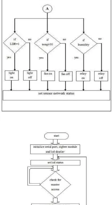
[image:3.595.325.510.298.638.2]
10 Fig.5 flow chart of sub-process of slave section.
4. IMPLEMENTATION
The schematic description has been explained. Now, let us discuss the way in which these components are connected and operate. ARM7 TDMI LPC 2148 Microcontroller board is interfaced with MAX 232 IC, reset circuit, crystal oscillator, inputs and outputs and then given to power supply.
The power supply unit needs to be connected to the microcontroller board. However the microcontroller requires only +5v DC voltage which is very small compared to the 230v AC mains supply. Hence the mains supply voltage needs to be down converted into the required voltage. This can be achieved by using a rectifier to convert the AC signal into PULSATING DC, then a capacitive filter to smoothen the signal further. Now the AC signal is converted into the DC but still needs to be regulated since the voltage might vary and this is achieved by using a regulator circuit which gives +5vDC as output. The power supply is given to the pin 23,41,51 and ground terminal is connected to the pin 6,18,25,42,50. Vref voltage supply is given to the pin 63 of micro controller board.
The reset circuit is essential to apply a trigger pulse which can reset the microcontroller. It consists of a switch, a resistor and a capacitor. When the switch is pressed it is shorted and the current chooses this least resistance path and so the trigger signal is generated which is applied to the microcontroller by
connecting the output of the circuit to the pin 57 of the ARM7TDMI LPC 2148 microcontroller board.
Fig 6. Schematic diagram of slave section
The input circuits like thermistor circuit, LDR circuit, humidity sensor circuit are connected to the pins 1,2 and3 of port 1 respectively. The output devices like relay circuits, LDR circuit, are connected to the pins 4, 60 and 64 of port 1 respectively. To transmit the data wirelessly, zigbee module is employed and interfaced through MAX232 and connected to the pins 19 and 21 of port 0.
When any of the input circuit signals goes abnormal, the corresponding output signal is activated. The input LDR circuit corresponds to the output BULB and the input circuits like thermistor and humidity circuits corresponds to the relay circuits which can drive different electrical devices like fan, AC, heater, etc.
The temperature sensor LM35 is used to detect the changes in the temperature. When the temperature sensor LM35 observes a change in temperature, it results in a high signal on the pin 4 of the microcontroller board. Then the respective pin 56 is made high and the output circuit driver motor is enabled. Since it is detecting temperature changes, the output circuit can be connected to the motor.
11 signal is placed on the pin 20 of the microcontroller).
This output is connected to the BULB through
RELAY and hence LDR can be used to control the light in a building. The humidity sensor is used to detect the amount of water vapour present in the air. When it detects the water vapour content in air, it sends the signal to the microcontroller board through pin 60 and the microcontroller sends the corresponding output signal to the fan through pin 52 of micro controller board. This way the humidity sensor is used to control the different parameters of the building.
All these inputs are placed in different buildings (node 1 and node 2 in our project) so that the different parameters of a building can control particular electrical devices. However, to give the user information about the status of the building, we need to monitor the status and then correspondingly send the data to the user. We chose wireless communication to transmit the status since wired communication can be complex. To implement this efficiently we used zigbee which has certain advantages over the other and can be implemented in a simple manner.
However, when different buildings try to transmit their status it can lead to conjunction at the receiver which is placed at the user. In order to avoid this, we developed our systems using master/slave technique. User is the master and the different building networks are the slaves. In master/slave technique the data can be transmitted from the slaves to the master only when the master requests it. This avoids the conjunction and also allocates the power of command to the user who acts as master. We also made sure that the output circuits can also be individually controlled. If the user wants to switch ON or switch OFF different electrical devices, user
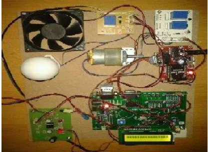
[image:5.595.77.285.117.269.2]transmits the corresponding command through the zigbee. Upon receiving the signal, the microcontroller controls the operation as desired.
Fig 8. Slave sections
5. RESULTS
The proposed system is a Building automation using DALI and wireless sensor networks. The zigbee technology provides wireless communication for master and slave sections. The below figures shows outcome of this project.
[image:5.595.320.520.549.737.2]We implemented a graphical user interface (GUI) in order to test the wireless sensor network and control the lighting. The GUI is installed in the computer host where the Coordinator is plugged in via USB. The user can send commands to the PAN coordinator using this GUI; allowing the user to switch on and off the lamps, dim and check some lamp parameters like the dimming level, lamp status, control gear or lamp failures, etc.
12 Although it was designed for lighting purposes it
does not suppose any effort to use is as a general BAS. In other words, up and down commands or direct levels can be also used for setting a fan speed or a blind position. System under test included several nodes with or without DALI ballast connected to them. We used ballast for 70 W HID lamps with DALI control interface.
The system has been tested in laboratories of our facilities. The overall performance shows a good coexistence in such a hostile environment (2.4 GHz ISM band is crowded with Wi-Fi and Bluetooth networks). The number of DALI devices under control was significantly increased, not only could we have a single DALI device with any sensor node, but a node could also control up more than one ballasts by making use of its MAC or network address and also the DALI short addresses.
6. CONCLUSION
A new remote management system for buildings lighting automation has been presented. With the use of wireless sensor networks we could be able to extend DALI initial capacity to a number big enough to be used in real scenarios such as residential areas and large buildings without additional investments in different DALI loop. The control through the user interface of the wireless sensor network also enables a centralized control system. The use of DALI devices with wireless sensor network allows a half-duplex
communication which can provide many parameters about the lighting and lamp status, this is very useful for saving energy and maintenance purposes, as it can detect any single lamp fault allowing a predictive maintenance and group replacement or schedule power consumptions rules enabling the integration of the lighting system in home and buildings into Smart Grid approaches, since we can monitor and act over them.
Further implementations can be done in order to extend the proposed system to other standard or technologies of lamps, luminaries or lightning communication and control protocols using different sensor networks and integrating them using a wireless technology and even trying to implement large complex networks.
REFERENCES
[1] F. J. Bellido-Outeirino et al.: “Building Lighting Automation through the Integration of DALI
with Wireless Sensor Networks” IEEE Transactions on Consumer Electronics, Vol. 58, No. 1, February 2012.
[2] Lighting Research Center, Rensselaer Polytechnic Institute, “Reducing barriers to the use of high-efficiency lighting systems,” Feb. 2002.
[3] M. Aliberti, “Green networking in home and building automation systems through power state switching,” IEEE Trans. Consumer Electron., vol. 57, no. 2, pp. 445-452 May 2011.
[4] D. Lechner, W. Granzer, and W. Kastner, “Security for KNXnet/IP,” Konnex Scientific Conf., Nov. 2008.
[5] W. S. Lee, S. H. Hong, “Implementation of a KNX-ZigBee gateway for home automation,” 13th IEEE Int. Symp. On Consumer Electron. (ISCE), pp. 545-549, May 2009.
[6] F. Ferreira, A. L. Osorio, J. M. F. Calado, and C. S. Pedro, “Building automation interoperability – A review,” 17th Int Conf. on Systems, Signals and Image Process (IWSSIP), Jun. 2010
[7] Y. Ma, and D. Wobschall, “A sensor network for buildings based on the DALI bus,” IEEE Sensors Applic. Symp. (SAS), Feb. 2007
[8] K. Gill, S. H. Yang, F. Yao, and X. Lu, “A ZigBee-based home automation system,” IEEE Trans. Consumer Electron., vol. 55, no. 2, pp. 422-430, May 2009.
[9] D. M. Han, and J. H. Lim, “Smart home energy management system using IEEE 802.15.4 and ZigBee,” IEEE Trans. Consumer Electron., vol. 56, no. 3, pp. 1403-1410, Aug. 2010.
[10]D. M. Han, and J. H. Lim, “Design and implementation of Smart home energy management systems based on ZigBee,” IEEE Trans. Consumer Electron., vol. 56, no. 3,
Author profile: