164
Comparative Study of Beam by Analytical Method and
ETABS Software
M.D. Pidurkar
1, R.H. Mohankar
2, R.S. Bute
3, Y.D. Chintanwar
4Asst Professor, Department of Civil Engineering, Priyadarshini J.L. College of Engineering1, 2, 3, 4 Email: [email protected]
Abstract-The design process of structural planning and design required not only imagination and conceptual
thinking but also sound knowledge of science of structural engineering besides the knowledge of practical aspect, such as recent design codes bye laws, backed up by ample experience and judgement for designing of beam, it is necessary to know the moments they are subjected to. For this purpose we use static method for analysis of beam.
Keywords-Beam, Analytical Method, ETABS Software
1. INTRODUCTION
Structural analysis deals with study and determination of forces in various components of a structure subjected to loads. As the structural system as a whole and the loads acting on it may be of complex nature certain simplifying assumptions with regard to the quality of material, geometry of the members, nature and distribution of loads and the extent of connectivity at the joints and the supports are always made to make the analysis simpler.
For the design of beam, flexibility method and Slope deflection method of analysis are mainly used, which allows the engineer to analyse beam easily and design it economically. The research is concluded by evaluating a selection of beam, with practical dimensions in order to substantiate the conclusions as stated below.
Beam: Beam is a structural element that is capable of
withstanding load primarily loads by resisting against bending. Beams are traditionally description of building or civil engineering structural elements, but smaller structure such as truck or automobile frame, machine frames and other mechanical or structural systems contain beam structure that are designed and analyzed in a similar fashion.
2. ANALYTICAL METHODS FOR
ANALYSIS
Slope and Deflection Method
Flexibility or Force Method
Moment Distribution Method
2.1 Flexibility Method:
Since twentieth century, indeterminate structures are being widely used for its obvious merits. It may be recalled that, in the case of indeterminate structures either the reactions or the internal forces cannot be determined from equations of statics alone. In such structures, the number of reactions or the number of internal forces exceeds the number of static equilibrium equations. In addition to equilibrium equations, compatibility equations are used to evaluate the unknown reactions and internal forces in statically indeterminate structure. In the analysis of indeterminate structure it is necessary to satisfy the equilibrium equations (implying that the structure is in equilibrium) compatibility equations (requirement if for assuring the continuity of the structure without any breaks) and force displacement equations (the way in which displacement are related to forces). We have two distinct method of analysis for statically indeterminate structure depending upon how the above equations are satisfied:
1. Force method of analysis (also known as flexibility method of analysis, method of consistent deformation, flexibility matrix method)
165 hence the method is being widely used in the modern
day structural analysis.
2.2 Slope Deflection Method:
This method was first devised by Heinrich Mandrels and Otto Mohr to study the secondary stresses in trusses and was further developed by G.A. Maney extend its application to analyze indeterminate beams and framed structures. The basic assumption of this method is to consider the deformations caused only by bending moments. It’s assumed that the effects of shear force or axial force deformations are negligible in indeterminate beams or frames.
By forming slope deflection equations and applying joint and shear equilibrium conditions, the rotation angles (or the slope angles) are calculated. Substituting them back in to the slope deflection equations, member end moments are readily determined.
3. METHODOLOGY ADOPTED
This paper presents the analysis of Beam, which is the most common in practice by using two most common methods via flexibility method & slope deflection method. The moment of inertia of both spans is I.
3m 3m 6m
Fig.1. Beam considered for the analysis
3.1. Application of Flexibility Method for the Analysis of Beam:
Fig2: unknown joints and displacement
3.1.1 Degree of Kinematic Indeterminacy:
DOKI is equal to the number of unrestrained degrees of freedom used in beam. It is the number of unknowns to be solved in the stiffness method.
DOKI = 3n – s
Where, n is the no. of nodes in the beam is equal to 3 and the total number of restraints for the beam is denoted here as s is 6.
Therefore DOKI = (3x3) - 6 = 3
3.1.2 Formulation of Members Stiffness Matrix:
SM =
SMAB =
SMBC =
3.1.3 Stiffness Matrix: In the given problem of the
beam, the degree of kinematic indeterminacy is equal to 3. Therefore the stiffness matrix should be of 3x3.
X =
Where,
K =
K =
3.2.3 Formulation of Load Matrix or Global Load Matrix:
20
37.5 50 37.5 26.67 26.67
3m 3m 6m
25 25 40 40
Fig.3. Figure shows fixed moments and forces
50 20kN/m
A
B
C
1
2
3
4
5
6
166 Action due to moment loading:
AML1 = , AML2 =
Action due to free co-ordinates:
AFC =
X =
EI xx =
By solving equation we get,
DF1=, DF2=, DF3=
Final Member Forces:
For span AB,
AM=+{X}
AMAB= & AMBC =
3.1.4 Final End Moments:
The final end moments have been calculated,
MAB = 0, MBA = + 49.5kNm, MBC = - 49.5 kNm
MCB = 0
3.2 Application of Slope Deflection Method for the Analysis of Portal Frame:
3.2.1 Fixed End Moments:
The fixed end moments of each member are,
FEMAB = - 37.5 kNm, FEMBA = + 37.5 kNm
FEMBC = - 26.67 kNm, FEMCB = + 26.67 kNm
3.2.2 Formulation of Members Slope Deflection Equation:
In the given problem, only joint B rotates. Hence, in this problem we have three unknown displacements to be evaluated. The ends A and C are hinge. Hence, θA =
θc =0
MAB = FEMAB +(2)---(i) MBA =
FEMBA +(2)---(ii) MBC = FEMBC
+(2)--- ---(iii) MCB = FEMCB
+(2)---(iv)
3.2.3 Applying Equilibrium Condition:
In the slope deflection method we have to calculate unknown joints, rotation and displacements.
Now, consider the summation of moment at A,
MAB = 0, 0.67EIθA+0.33EIθB=37.5... (A)
Now, consider the summation of moment at B,
MBA + MBC =0
0.33EI θA+1.67 EI θB+0.5EIθC = -10.83………..(B)
Now, consider the summation of moment at C,
MCB = 0, 0.5EIθB+ EI θC= -26.67…………...(C)
On solving the equation (A), (B) & (C) we get,
θA= , θB =, θC =
3.2.4 Final End Moments:
Substituting the values of θA, θB and θC in the slope deflection equations we get the final end moments.
MAB = 0, MBA = +49.5 kNm, MBC = -49.5 kNm
MCB = 0 kNm
3.2.5 Bending Moment Diagram
A B C
Fig.4. Final Bending Moment
40KNm
75kN
m
49.5KNm-
+
167
Fig 5: Shear force diagram
3.2.6Analysis by ETABS software:
ETABS is the present day leading design software in the market. Many design companies use this software for their project design purpose. So, this paper mainly deals with comparative analysis of beam, the results obtain from the analysis of beam structure by slope deflection method & flexibility method and using ETABS software separately.
ETABS is used to compare the results which are obtaining by analytical method.
Fi g.5.Figure shows bending moment diagram
After analysing the beam structure the moments obtained are approximately same analytical method.
The results obtained from analytical method and software ETABS are shown in table 1 & table 2.
The shear force also calculated by analytical method and software ETABS which are shown in table 3.
Fig 6:figure shows shear force diagram
4. INVESTIGATIVE ANALYSIS
After the analysis is completed, the result of the end moments of the considered beam has been compared and an investigative analysis is done.
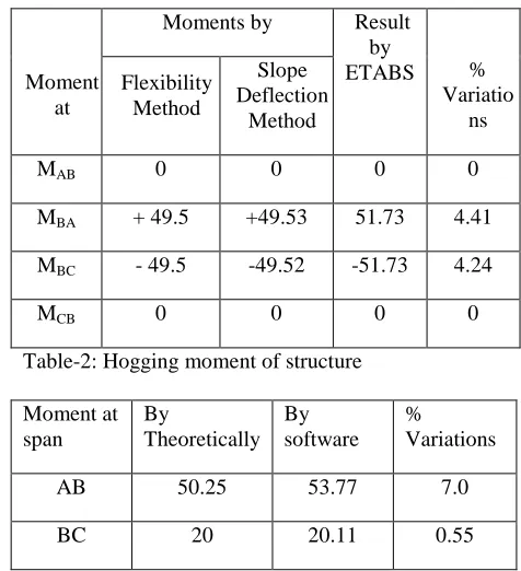
Table-1: Sagging Moment of structure
Moment at
Moments by Result by
ETABS % Variatio
ns Flexibility
Method
Slope Deflection
Method
MAB 0 0 0 0
MBA + 49.5 +49.53 51.73 4.41
MBC - 49.5 -49.52 -51.73 4.24
MCB 0 0 0 0
Table-2: Hogging moment of structure
Moment at span
By
Theoretically By software
% Variations
AB 50.25 53.77 7.0
BC 20 20.11 0.55
Table-3: Shear force of the structure
By Theoretically By Software % Variations
16.73 19.38 15.83
33.27 36.46 9.58
52.37 54.75 4.54
27.62 29.14 5.50
33.27kN
27.62k
16.73k
52.38
kN
-
-
168
5. CONCLUSIONS
The hogging moments calculated by the application of analytical method of considered beam, mostly matches with those calculated by ETABS software.
The sagging moments calculated by the application of analytical method of considered beam, mostly matches with those calculated by ETABS software. The shear force calculated by analytical method and ETABS software is also approximately same, but in the analytic method has slightly variation in end moments.
In analytical method mainly considered slope deflection method and flexibility method gives same result moments and shear force.
In Slope deflection method, where we know directly the given unknown joints, displacement and rotations of any structure (Beam).
REFERENCES
[1] R. H. Mohankar, M. D. Pidurkar, P. Patil “Comparative study of end moments regarding application rotation contribution method,Kani’s Method & Moment Distribution Method for the Analysis of Portal Frame”(Vol 7, Issue 1 (May-June 2013)
[2] Shachindra Kumar Chadkar, Dr. AbhaynSharma “Comparative study of RC moment resisting frame of variable height with steel bracing and shear wall” (Vol.3,Issue 1,April 2015)
[3] Shashikala Koppad, Dr. S. V. Itti “Comparative Study of RCC and Composite Multi storied building” (Vol.3,Issue 5, Nov 2013)
[4] V. Varalakshmi, G. Shivkumar, R .Sunil Sharma, “Analysis and design of G+5 residential building” (2014)