Overview of the Battelle Integrity of Nuclear Piping (BINP) Program
Paul M. Scott ~, Richard J. Olson ~, Gery M. Wilkowski 2, Naoki Miura 3, Young-Hwan Choi 4, Tsun-Yung Chang s, and Nilesh Chokshi s
ABSTRACT
Since the early 1980's, researchers at Battelle, in cooperation with the USNRC and the members of the International Piping Integrity Research Groups (IPIRG), have conducted extensive research aimed at developing a better understanding of the fracture behavior of piping and piping systems in commercial nuclear power plants. While the results of these research programs have significantly advanced the state-of-the-art in understanding the fracture behavior of cracked piping, there remains a number of key issues that need to be resolved in order to develop the necessary technical basis for formulating technical and regulatory positions regarding these issues.
In 1998 the Battelle Integrity of Nuclear Piping (BINP) Program was formed in order to address the most critical of these outstanding issues. Some of the questions to be answered through the research conducted during this program are:
• How should secondary stresses be treated in fracture analyses?
• What effect do cyclic stresses from seismic load histories have on the fracture of cracked piping systems? • How should failure margins be determined for cracked piping system analyses, specifically for the case where
the piping system has undergone significant plastic deformation?
• What are the effects of pipe-system boundary conditions on the crack-opening-displacements required for leak- before-break (LBB) analyses?
• What impacts do the differences between Class 1 and Class 2/3 and balance of plant piping have on in-service flaw evaluation?
This paper will provide an overview of the key results obtained to date from this program, as well as provide a review of the future plans and direction for the BINP program.
INTRODUCTION
Over the past 20 years, a significant amount of research on nuclear pipe fracture behavior has been conducted. At Battelle-Columbus, numerous significant research programs have been conducted for the US Nuclear Regulatory Commission (USNRC) and its international partners through the International Piping Integrity Research Group (IPIRG) programs. As a result of these programs, the state-of-the-art in piping fracture technology has been significantly advanced. At the conclusion of the Second IPIRG program, the question was posed as to whether there remained any holes in the pipe fracture evaluation technology that still needed to be addressed. At that time, Battelle was charged with the responsibility of conducting an uncertainty analysis with the goal of identifying any shortcomings in the research related to the issue of piping integrity in nuclear power plants (Ref. 1). Subsequent to that study, the USNRC assembled a team of independent experts in the field of piping integrity issues to meet with teams of engineers and researchers from various research laboratories and nuclear industry vendors to further ascertain what additional research in the area of piping integrity may be appropriate. Battelle-Columbus was one of the organizations this team of experts met with to review results of pipe fracture research conducted over the last 20 years. An outgrowth of the uncertainty analysis and this review process was the perceived need for the Battelle Integrity of Nuclear Piping (BINP) program. The overall objective of this program is to address the most important issues that were identified in the Battelle uncertainty analysis and the USNRC piping fracture review process, with the ultimate aim of providing the technical basis and justification for establishing technical and regulatory positions.
The current members in this international cooperative research program are the USNRC, the Central Research Institute of Electric Power Industry (CRIEPI) in Japan representing various Japanese utilities, the Korea Institute of Nuclear Safety (KINS) representing a consortium of interest groups in Korea, and now the Atomic Energy Commission in the Republic of China (AEC-ROC) representing a consortium of interests in Taiwan.
The currently funded technical tasks in the program include:
• Task 1 - Evaluation of Procedures for Treatment of Secondary Stresses in Pipe Fracture Analyses • Task 2 - Conduct of a Pipe-System Experiment with an Alternative Seismic Input Function • Task 3 - Determination of Actual Margins in Plant Piping
• Task 4 - Assessment of Pipe-System Boundary Condition Effects on Crack-Opening Displacement (COD) Analyses for Leak-Before-Break (LBB) Analyses
• Task 7 - Development of Flaw Evaluation Criteria for Class 2, 3, and Balance of Plant (BOP) Piping
1 Battelle-Columbus,
2 Engineering Mechanics Corporation of Columbus,
3 Central Research Institute of Electric Power Industry (Japan), 4 Korea Imtimte of Nuclear Safety,
5 United States Nuclear Regulatory Commission
SMiRT 16, Washington DC, August 2001 Paper # 1758
In addition, now that Taiwan has joined the program, a new task on the Effect of Weld Residual Stresses on COD Analyses for LBB Analyses will be added to the program.
In the paper that follows, some of the key results to date and status of ongoing activities will be presented.
SUMMARY OF RESULTS TO DATE
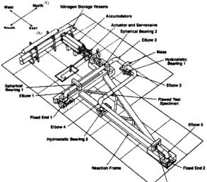
At this time, Task 1 and 2 are essentially complete. Both of these tasks were experimental in nature, both revolving large pipe-system experiments conducted in the IPIRG pipe loop experimental facility, see Figure 1.
West ,l" Nl~ogm ~omge VeHem
tdlnS
EI)ow I
I~t~ 3
Fired E]141" ~ . ~
tltH~ 4 / I~Usow S
Rmwalon ~ limt2
Figure 1. IPIRG pipe loop experimental facility used in BINP Task 1 and Task 2 pipe-system experiments
Task 1 - Preliminary Results
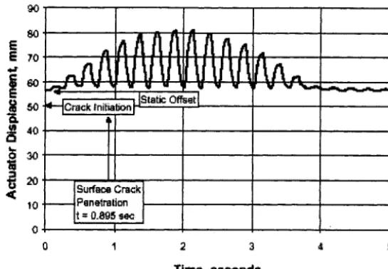
The test specimen for the Task 1 experiment was a section of 16-inch diameter Type 304 stainless steel pipe with a circumferential surface crack in the center of a relatively low-toughness stainless steel submerge-arc weld (SAW). A companion pipe-system experiment had previously been conducted as part of the First IPIRG program (Experiment 1.3-5). The distinguishing feature of the BINP Task 2 experiment, with respect to Experiment 1.3-5, was that the actuator was intentionally offset 2.2 inches in the Task 2 experiment (with respect to where the actuator was at the start of Experiment 1.3- 5) before the application of the dynamic load history to simulate a large thermal expansion stress, see Figure 2. As a result, the initial static moment (moment simulating thermal expansion moment) was 3,100 in-kips compared with an initial static moment of 747 in-kips for Experiment 1.3-5. Once the dynamic excitation was applied, the BINP Task 1 test specimen failed (surface crack penetrating the pipe wall thickness) in 0.895 seconds compared with 2.59 seconds for Experiment 1.3-5. The total moments (static plus dynamic) at surface crack penetration for the two experiments were similar, especially when small differences in test conditions (e.g., initial crack size) were considered. What this suggests is that secondary stresses, such as those attributable to thermal expansion, play just as large a role in pipe fracture as do primary stresses.
90
80
E
E 70
,o.-f
tO
Offset
Surface Crack Penetration
]
0 1 2 3 4 5
Time, Seconds
Figure 2. Displacement-time history used in BINP Task I Experiment
Task 2 - Preliminary Results
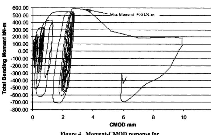
The objective of this experiment was to design and conduct a pipe-system experiment with a "more damaging" simulated-seismic load history than the one applied to Experiment 1-1 in the Second IPIRG program The seismic history associated with Experiment 1-1 involved a series of elastic loadings followed by one large plastic cycle which was again followed by another series of elastic type loadings, see Figure 3. As a result, it was felt that this forcing function was not a true evaluation of the effect of cyclic loading on the fracture behavior of cracked piping systems. Consequently, the objective of the design of the Task 2 experiment was to develop a seismic history with a more gradual build-up of the cyclic load history so that there would be more plastic cycles applied before the surface crack penetrated the pipe wall thickness. Figure 4 shows the moment-CMOD curve for the BINP Task 2 experiment, showing approximately 5 to 7 plastic cycles prior to the surface crack penetrating the pipe wall thickness.
When the normalized maximum moments I for the two experiments were compared, it was found that the BINP Task 2 normalized maximum moment was approximately 25 percent lower than the normalized maximum moment for Experiment 1-1 from the Second IPIRG program. While at first glance this seems significant, part of this decrease is most likely attributable to unaccounted for differences in material property data, i.e., the fracture toughness. While the test specimens were both fabricated from 16-inch diameter Type 304 stainless steel pipe, the heat of pipe used for the test specimen for the BINP Task 2 experiment had a much higher sulfur content than did the heat of pipe used to fabricate the test specimen for Experiment 1-1 (Ref. 2). The higher sulfur content results in a lower J-R curve that has been shown in another paper in these proceedings 2 to lower the moment-carrying capacity by up to 10 to 15 percent. Consequently, at least part of this lowering of the normalized moment for the BINP Task 2 experiment (when compared with Experiment 1-1) is probably attributable to this difference in fracture toughness. As a result, while it appears that this "more damaging" load history for the BINP Task 2 experiment had an effect on the load-carrying capacity, it is probably not the 25 percent reduction originally thought.
t The maximum moments are normalized by the Net-Section-Collapse (NSC) moments to account for small differences in test conditions, e.g., flaw size differences.
I
:~o L
100 r-
/ , ~ ; ... / ; i t /
-~o :i
- ~ o ~ .i , .
"<'° r 7
-,0.I O;i
; " ' i
• i 4 !
, t J
~iI"
/
!
e f
. .,,. ... ,," ....
I . . .. . . if?. S
,'/~, /
. . . ~ _ , ,:~....ll., . ! . . . ,~., ... [ . . . i ... I ~ ,~ " ,
0,;9 O.S o.~ t)~ tJ
T m ~ li,,mm'.m ~ } 0 d O
Figure 3. Moment-rotation response for Experiment 1-1 from
the Second IPIRG program
600.00 500.00
400,00
,,., 200.0~
I~ 100.00
i
0-00
-100.00
.2oo.oo!-300.00
al -400.00
ram.
~ ,-500.00
-600.00
:.700.00 -800.00i'vK~mcaS 5 9 0 k N . m
0 2 4 6 8 10 t2
CMOD mm
Figure 4. Moment-CMOD response for
the BINP Task 2 experiment
SUMMARY OF ONGOING ACTIVITIES
The ongoing activities associated with the BINP program are summarized next.
Task 3 - Margin Assessment Task
analysis is a load-controlled loading. In reality, the presence of the crack can influence the behavior of the rest of the piping system, and furthermore, piping sections remote from the crack can yield and absorb some of the energy that is assumed available to grow the crack.
Results of analyses and experiments conducted to date have .provided a strong indication that flawed piping can withstand far greater loads without failure than traditional flaw evaluation methods suggests. Comparing measured experimental moments and calculated moments for some of the IPIRG experiments, the linear-elastic moments were as much as 40 percent higher than the measured moments. Thus, the crack driving force is being grossly overestimated. As a result, the scope of this task involves analysis of actual plant piping with assumed flaws under seismic loading using both traditional and nonlinear analyses to quantify the real margins that exist against failure. Analyses will involve:
• linear-elastic, uncracked, baseline analyses,
• nonlinear cracked pipe analyses in which the piping system model consists of linear beam elements with a nonlinear crack element, and
• nonlinear cracked pipe analyses in which the piping system model consists of nonlinear beam elements with a nonlinear crack element.
Task 4 - Effect of Piping System Boundary Conditions on COD Predictions for LBB Analyses
The objective of this task is to develop an analysis procedure that can be used to assess the effect of pipe system boundary conditions on the crack-opening-displacement, and thus detectable crack lengths, of through-waU cracks that may be considered in LBB evaluations.
As part of Reference 1, a series of deterministic and probabilistic analyses were conducted to ascertain how much of an effect the restraint invosed by the rest of the piping system has on the crack-opening displacement predictions typically used in LBB analyses. The results of those analyses are shown in Figure 5. The normalized restraint length in Figure 5 (x- axis) is the distance from the crack plane to the nearest restraint (e.g., nozzle) normalized by the pipe diameter. The normalized COD (y-axis) is the predicted COD, considering the effect of restraint, normalized by the predicted unrestrained C O D . In Figure 5, analyses were conducted for two different pipe diameters, i.e., 4-inch and 28-inch. For typical LBB evaluations, the normalized crack length of the large diameter case (28-inch) will be relatively short, i.e., 2/B approaching 1/8 or less. As can be seen in Figure 5, for such a case, the effect of restraint of pressure induced bending is insignificant. However, for the small diameter piping system (4-inch), the normalized crack length will be much longer for typical LBB evaluations, i.e., 2/B approaching ¼ to ½. As can be seen in Figure 5, for such cases, the effect of restraint on the COD is significant, especially when the postulated crack plane is near a restraint, i.e., normalized restraint length approaching 1.
As part of the BINP program this analysis method will be further enhanced. At this time, a number of new analyses have been conducted to further quantify these results. The initial analyses conducted were conducted as part of a round robin problem that each of the BINP Technical Advisory Group (TAG) members solved. Battelle and Engineering Mechanics Corporation of Columbus (Emc 2) staff also provided solutions. Once these solutions were developed and reviewed by the group, staff from Emc 2 synthesized and compiled the results into an analyses routine for predicting the effect of restraint of bending on the COD, and thus detectable crack length, on predictions for LBB analyses. In the near future, this work will be extended through a series of cracked pipe-system analyses.
Task 7 - Development of Flaw Evaluation Criteria for Class 2, 3, and BOP Piping
Class 2, 3, and BOP piping are being inspected more frequently due to increased inspection requirements in the ASME Code. However, the existing ASME code flaw evaluation criteria are only for Class 1 piping. It is also of note that some Class 2 and 3 piping system are more important relative to plant risk analyses than Class 1 piping. As a result, flaw evaluation criteria for these piping systems are needed.
0 , 9 -
0 . 8 - \ ... . . 1 o . . . . . , ! , " o
0 . 7 -
0 to 0.6
"0
._~ 0 . 5 -
. = . , . =
( I
E 0.4-
O
Z
0.:3-
0 . 2 -
0 . 1 -
~ - 1/2
Closed da~a points - 28-inch diameter, Rm/t = 10 Open data points - 4-inch diameter, Rm/t = 6
O I "' I "1 I I I ! I ' I 1
0 2 4 6 8 10 12 14 16 18 20
Normalized Restraint Length
Figure 5. Effect of normalized restraint length on predicted COD
The main technical differences between Class 1 piping and Class 2, 3, and BOP piping are that the Class 2, 3, and BOP piping may have higher R/t ratios and may operate at lower temperatures than Class 1 piping. Higher R/t ratio piping tend to have lower failure stresses than the R/t piping typically used in Class 1 piping. The lower operating temperature raises the potential concern of brittle fracture.
In order to begin the process of developing the technical basis for in-service flaw evaluation for such piping systems, both of these effects (R/t and transition temperature) will be addressed as part of this task. As part of the R/t ratio subtask, three distinct activities are planned:
• Quantify the effect of R/t ratio on the elastic F-functions.
• Examine the effect of R/t ratio on some of the existing elastic-plastic fracture mechanics (EPFM) J-estimation schemes.
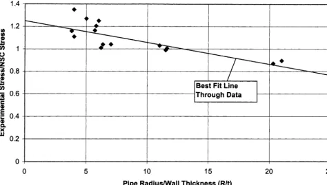
• Extend the limit-load R/t ratio correction factor developed as part of References 3 and 4 (see Figure 6) to higher R/t ratio values, i.e., up to an R/t of 40.
As part of the transition temperature subtask, two major activities will be undertaken: • Review existing data on transition temperature effects for surface-cracked ferritic pipe. • Conduct pipe and specimen experiments are various temperatures.
Note, the level of effort assigned to this task will be dependent on whether or not AEC-ROC ultimately joins this program. If not, then the pipe and specimen experiments at various temperatures will probably not be conducted. Also, the scope of some of the other activities may have to be cut back.
_
1.2 I/) U)
,4,,,I
u) 1
O
(n z
0.8
i._ ,4,11
"R 0.6
er
E
• c. 0.4 Q. X U,I
0 . 2 -
, , 4 . . .
A
. . . .
0 5 10 15
Best Fit Line T h r o u g h Data
20 25
Pipe Radius/Wall Thickness (R/t)
Figure 6. Plot of the ratio of the experimental stress to the predicted stress as a function of pipe R/t ratio for pipes expected to fail under limit-load conditions
Task 9 - Effect of Weld Residual Stresses on COD Predictions for LBB Analyses
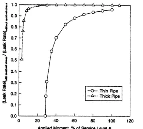
This is a task that will only be undertaken once AEC-ROC joins the program. It is an important task for LBB considerations in that work conducted as part of the Uncertainty Analyses from the Second IPIRG program (Ref. 1) showed that weld residual stresses can have a significant effect on the crack-opening-displacements used in LBB analyses. As part of Reference 1, it was shown that this effect was particularly acute for "thin-wall" piping. For thin wall piping, the tension- compression residual stress field through the thickness of the weld was found to cause a rotation of the crack face such that at relatively low operating loads, the crack face rotations were large enough to completely pinch off the opening, thereby reducing or stopping the flow through the crack. For thick wall piping, the tension-compression-tension through thickness residual stress field was not so problematic from a LBB perspective. Figure 7 shows some predictions of normalized leak rates (predicted leak rate considering residual stresses normalized by predicted leak rate without considering residual stresses) as a function of the applied moment as a percentage of the Service Level A moment.
The scope of activities associated with this task will be to further quantify this effect through the development of a weld residual stress COD correction factor that can be incorporated into the USNRC's Reg. Guide on LBB. As part of this effort, a definition of "thin wall" and "thick wall" piping will be developed.
SUMMARY
= 1.0 tt
....t t).tt
0,7
'~ 0.6
R -
~ 0.5 0.4
0.3
0.2
0.1
0.0
.,¢"
X
I_l
I
f
I
-t
!
[ ~ Thin PiPe
- ' -,~,'-- ThiCk: Pipe
0 20 40 60 80 100 120
Applied Moment, % of Service Level A
Figure 7. Ratio of leak rates, with and without residual stresses,
as a function of applied load
ACKNOWLEDGEMENT
This work was performed for the Battelle Integrity of Nuclear Piping Program (BINP). Members of the BINP program are the U.S. NRC (Drs. Nilesh Chokshi and Tsun-Yung Chang have been the NRC-RES representatives), CRIEPI in Japan for various Japanese utilities (Mr. N. Miura is the representative), KINS/KOPEC/KEPRI in Korea (Dr. Young-Hwan Choi is the representative), and AEC-ROC/INER/Taiwan Power in Taiwan (Dr. L. C. Kang is the representative). We thank the BINP members for their Support of this effort.
DISCLAIMER
This work was performed partially under the auspices of the U.S. Nuclear Regulatory Commission. It presents information that does not currently represent an agreed-upon staff position. NRC has neither approved or disapproved its technical content.
REFERENCES
1. Ghadiali, N., Rahman, S., and Wilkowski, G., "Deterministic and Probabilistic Evaluations for Uncertainty in Pipe Fracture Parameters in Leak-Before-Break and In-Service Flaw Evaluations," NUREG/CR-6443, June 1996.
2. Rudland, D. L., Brust, F. W., and Wilkowski, G. M., "Fracture Toughness Evaluations of TP304 Stainless Steel Pipes," NUREG/CR-6446, February 1997.
3. Wilkowski, G. M., and Scott, P. M., "A Statistical Based CircumferentiaUy Cracked Pipe Fracture Mechanics Analysis
for Design or Code Implementation,"