ISSN(Online): 2319-8753 ISSN (Print): 2347-6710
I
nternational
J
ournal of
I
nnovative
R
esearch in
S
cience,
E
ngineering and
T
echnology
(A High Impact Factor & UGC Approved Journal)
Website: www.ijirset.com
Vol. 6, Issue 9, September 2017
Bandwidth Enhancement of UWB slot
Antenna with EBG Structures
Jasdeep Kaur, Kanika Arora
Assistant Professor, Department of Electronics Technology, Guru Nanak Dev University, Punjab, India
Department of Electronics Technology, Guru Nanak Dev University, Punjab, India
ABSTRACT:In this research work, various electromagnetic band gap structures (EBG) are proposed for improving the return loss and impedance bandwidth of an UWB antenna. The comparative parametric analysis has been made on the basis of factors such as return loss, gain, radiation pattern characteristics and impedance bandwidth. The analysis has been made on an UWB antenna consisting of four slots in its radiating patch with five different types of EBG configurations using HFSS (High Frequency Structural Simulator).
KEYWORDS: Ultra Wideband (UWB), Microstrip Patch Antenna, Electromagnetic Band Gap Structure (EBG) I. INTRODUCTION
There has been immense utilization of electromagnetic band gap (EBG) structures in the electromagnetic and antenna community nowadays [1]. These structures are artificially engineered objects which may be periodic or non-periodic in nature, which helps prevent the propagation of electromagnetic waves within a specific frequency band regardless of different incident angles and state of polarizations [2]. The primary advantage of employing an EBG structure in the ground plane is their ability to suppress the currents generated by the surface waves which reduce an antenna’s efficiency and its radiation pattern. These EBG structures enhance the performance of a microstrip antenna by utilizing the inherent properties of the dielectric materials used. There are two ways to improve the gain of an antenna by utilizing EBG structures by using it as superstrate [3-4] or as a ground plane [5-6]. The EBG characteristics can be governed by Shape, Size, Symmetry and Material used. There are numerous advantages of EBG and mainly is to enhance the Bandwidth and gain of an antenna. Even, it helps to improve isolation gain and diversity in MIMO systems [7-9], also provides notch characterization in UWB antennas [10], can suppress noise and reduce EMI in high speed circuits [11-14].
II. RELATEDWORK
Marie Chantai Mukandatimana et. al. (2004) [26] proposed a multi-resonator microstrip line fed patch antenna for dual band operation using two rectangular patches separated by an air gap which was U-shaped in nature. The two resonant frequencies obtained were 2.3 and 5.5 GHz which were characterized by good omnidirectional radiation patterns and acceptable input impedance, because monopole antennas offered wider bandwidth on being fed by microstrip line.
E. Cheltiar et. al. (2004) [27] obtained wideband characteristics by employing a U-shaped slot on the rectangular patch. This paper presented the analyzed results for higher as well as lower dielectrics on the basis of different empirical equations for calculating the resonant frequencies simulated by different parametric conditions. It was concluded that the resonant frequencies obtained by both formulations were in good agreement for low permittivity substrates used for the U-shaped slot antennas, and the accuracy decreased in the case of high permittivity substrates since they required more and longer cycles for optimization to obtain results suitable for wideband communication.
ISSN(Online): 2319-8753 ISSN (Print): 2347-6710
I
nternational
J
ournal of
I
nnovative
R
esearch in
S
cience,
E
ngineering and
T
echnology
(A High Impact Factor & UGC Approved Journal)
Website: www.ijirset.com
Vol. 6, Issue 9, September 2017
The paper discussed both the simulated and experimentally investigated results for return loss and radiation pattern of the antenna.
Evangelos S. Angelopoulos et. al. (2006) [30] tested four prototype antennas with circular and elliptical slot, three being fed by CPW and one being fed by microstrip feed line method. The prototypes were studied in terms of impedance bandwidth, radiation efficiency and characteristics of radiation patterns and the measured impedance bandwidths were obtained beyond 175 %. It was observed that by transforming the feed line from CPW to microstrip line helped preserve the UWB characteristics along the radiation profile.
Mohammad Ojaroudi et. al. (2009) [32] proposed an Ultra Wideband antenna consisting of rectangular slots in the square radiating patch accompanied by a T–shaped notch in the ground plane. The prototype was investigated for the effects of both with and without slots and the notch and was optimized for the antenna dimensions. The optimized design yielded a fractional bandwidth of 120% and an enlarged bandwidth range from 3.12 to 12.73 GHz.
Dalia Nashaat Elsheakh et. al. (2009) [34] designed and characterized a UWB antenna using a semicircular radiating patch and used the Spiral Artificial Magnetic Conductor (AMC) as the ground plane which helped diminish the antenna size and the cross polarization effect, and an increase in the gain of the antenna and bandwidth. Furthermore holes were drilled in the substrate surrounding the radiator to remove the discontinuities and surface wave propagations. The investigated bandwidth came out to be from 1 to 35 GHz with an efficiency of 0.92.
Hsien-Wen Liu et. al. (2010) [35] fabricated and tested a UWB antenna with band notching characteristic. The prototype developed was very compact compared to other antennas. It consisted of a square slot patch with a coupling strip in vertical direction which flexibly controlled the rejection of frequency interferences from WLAN (5.15-5.85 GHz) and WiMAX (5.25-5.85 GHz) in UWB operations. The proposed prototype was found to be suitable for integration into portable UWB devices due to features like omni directionality, stability in transmission characteristics and very efficient pulse handling for high data rate systems.
Jianjun Liu et. al. (2010) [36] proposed a multiband printed UWB antenna for wireless systems. The geometry was comprised of an elliptical radiating patch accompanied with a tapered microstrip feed line. The simulated results reported an extremely wide impedance bandwidth of 1.08 to 27.4 GHz. Thus, the antenna was found capable for serving multiple wireless services as well as wide spectrum monitoring RF based scavenging applications.
Rezaul Azim et. al. (2011) [39] introduced a very compact tapered shaped slot antenna fed by a microstrip feed line. It also consisted of a tuning stub etched on the opposite side of the radiating patch. The prototype was studied on the basis of several parameters such as the effect of various tuning stubs, effect of different slot shapes and that of the feeding gap too. The proposed antenna was found in accordance with the appropriate impedance matching, constant gain, omnidirectional pattern and an enlarged bandwidth from 3-11.2 GHz.
Zheng Guo et. al. (2013) [43] introduced an enhanced bandwidth monopole UWB antenna suitable for all mobile applications. Two methods were employed to increase the bandwidth; the first one was the introduction of new slots in the ground plane which enhanced the bandwidth to 9.33 GHz and the second method was to embed the antenna structure with conventional mushroom type electromagnetic band gap (CMT-EBG) which further enhanced it to 9.47 GHz. Both these methods posed least effect on radiation patterns and the basic frequency curves compared to that of the conventional prototype antenna.
III.METHODOLOGYOFSTUDY
We have utilized the ground plane as an EBG structure for studying the effect of various shapes of these structures over the bandwidth of the proposed antenna. Also, here we have used full ground plane instead of the partial one. Five types of EBG structures are studied in this section whose configurations are DISCUSSED in the following sub-sections.
1.3.1 Ground Plane with Circular Shaped Holes as EBG:For designing circular holes as EBG in the ground plane, circles of radius 1.5mm are made with a distance of 1mm between each other which may result in reduced weight and volume [18]. Hence, the whole ground plane is represented by these EBG structures
ISSN(Online): 2319-8753 ISSN (Print): 2347-6710
I
nternational
J
ournal of
I
nnovative
R
esearch in
S
cience,
E
ngineering and
T
echnology
(A High Impact Factor & UGC Approved Journal)
Website: www.ijirset.com
Vol. 6, Issue 9, September 2017
1.3.3 Ground Plane with Square Shaped Holes separated by Cylinders as EBG:For further reduction in the surface waves of the antenna and for reducing the interference the square shaped EBG’s are separated by cylinders in the middle [19]. This design is an extension of the design taken in the previous section with an addition of cylinders drilled along the center of the substrate so as to avoid the mutual coupling between the two square arrays. These cylinders have radii of 1.5 mm, a height of 1.6 mm and distance between their centers as 2 mm.
1.3.4 Ground Plane with Cylindrical Holes as EBG:In this configuration, the cylindrical holes are embedded throughout substrate thickness in triangular lattice form to study its effect on bandwidth and the surface wave radiations [16]. The radius of each individual cylinder is 1.5 mm, with a height of 1.6 mm separated at a distance of 4.5 mm along Y-axis and 4 mm along X-axis in order to be in triangular lattice form structure.
1.3.5 Ground Plane with Mushroom Type EBG:This EBG structure is the most conventional type of three dimensional structures used which consists of a solid patch with a cylindrical via. The transmission response of mushroom type EBG depends upon the size of the patch, diameter of via and the gap between the unit elements. The transmission characteristic also depends upon the thickness of the substrate and the substrate material [17]. The size of unit element for building the mushroom type structure is 1.5 mm × 1.5 mm at a height of 0.8 mm. The via diameter is taken as 0.6 mm while the gap between unit element is taken as 1 mm.
IV.EXPERIMENTALRESULTS
In lieu of drawing a comparative analysis between the different types of EBG structures used here, we have studied the performance characteristics by using FR-4 Epoxy (€ = 4.4).
1.4.1 Return Loss Characteristics: This is the very first parameter under study which is carried out at the solution frequency of 3.5 GHz for the three different materials stated above. Here also we get two resonating frequencies due to EBG structures in the ground plane. Also these EBG structures have effects on lower and upper frequencies which will ultimately affect the impedance bandwidth of the antenna. The following fig 5.35 – 5.39 depict the return loss plots for different EBG configurations of the slot antenna.
(a) (b)
ISSN(Online): 2319-8753 ISSN (Print): 2347-6710
I
nternational
J
ournal of
I
nnovative
R
esearch in
S
cience,
E
ngineering and
T
echnology
(A High Impact Factor & UGC Approved Journal)
Website: www.ijirset.com
Vol. 6, Issue 9, September 2017
Fig1.1: Return Loss Plots for Circular Shaped Holes , Square Shaped Holes, Square Shaped Holes separated by Cylinders, Cylindrical Holes, Mushroom Type
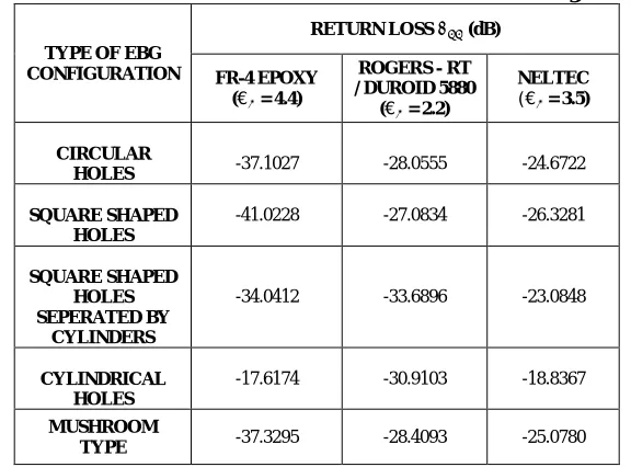
The table 1.1 represents the minimum return loss values obtained for the five different EBG configurations under study with three different substrate materials namely; FR-4, Rogers and Neltec. It is observed on comparative analysis; the minimum value of -41.0228 is obtained for square shaped holes EBG with the FR-4 material being used. Also from moving left to right of the table we observe a gradual increase in the values with the change of respective materials under consideration.
Table 1.1: Obtained Return Loss Values for Different EBG Configurations
TYPE OF EBG CONFIGURATION
RETURN LOSS (dB)
FR-4 EPOXY (€ = 4.4)
ROGERS - RT / DUROID 5880
(€ = 2.2)
NELTEC
(€ = 3.5)
CIRCULAR
HOLES -37.1027 -28.0555 -24.6722
SQUARE SHAPED HOLES
-41.0228 -27.0834 -26.3281
SQUARE SHAPED HOLES SEPERATED BY
CYLINDERS
-34.0412 -33.6896 -23.0848
CYLINDRICAL HOLES
-17.6174 -30.9103 -18.8367
MUSHROOM
TYPE -37.3295 -28.4093 -25.0780
1.4.2 Radiation Pattern Characteristics
ISSN(Online): 2319-8753 ISSN (Print): 2347-6710
I
nternational
J
ournal of
I
nnovative
R
esearch in
S
cience,
E
ngineering and
T
echnology
(A High Impact Factor & UGC Approved Journal)
Website: www.ijirset.com
Vol. 6, Issue 9, September 2017
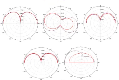
Fig 1.8: Radiation Pattern of Mushroom Type EBG (a) FR-4 (b) Rogers (c) Neltec
Table 1.2 below depicts the maximum gain values obtained for the different EBG structures under study. The gain values are calculated at the solution frequency of 3.5 GHz for the three respective materials under consideration. We observe that the maximum value is 4.7160 and 4.5738 respectively for the square holes as EBG in the ground plane when FR-4 epoxy and Rogers is used as the substrate, while the highest value is 5.1634 for circular holes as EBG when Neltec is used as the substrate.
Table 1.2: Maximum Gain Values for Different EBG Configurations
TYPE OF EBG CONFIGURATION
MAXIMUM GAIN (dB)
FR-4 EPOXY (€ = 4.4)
ROGERS - RT / DUROID 5880 (€ = 2.2)
NELTEC
(€ = 3.5)
CIRCULAR HOLES 4.2660 3.7545 5.1634
SQUARE SHAPED
HOLES 4.7160 4.5738 3.0838
SQUARE SHAPED HOLES SEPERATED BY
CYLINDERS
3.2118 3.3539 4.1888
CYLINDRICAL
HOLES 2.1833 3.2596 3.0889
MUSHROOM TYPE 4.6054 3.9663 4.2526
1.4.3 Impedance and Percentage Bandwidth
ISSN(Online): 2319-8753 ISSN (Print): 2347-6710
I
nternational
J
ournal of
I
nnovative
R
esearch in
S
cience,
E
ngineering and
T
echnology
(A High Impact Factor & UGC Approved Journal)
Website: www.ijirset.com
Vol. 6, Issue 9, September 2017
and Neltec substrates, while in case of FR-4 we have a constant trace characteristic in the return loss plot which can be utilized for the bandwidth calculations.
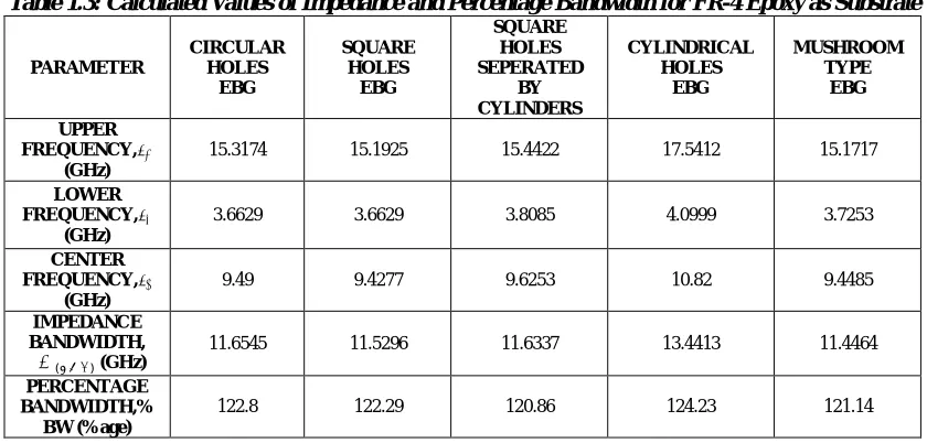
Table 1.3: Calculated Values of Impedance and Percentage Bandwidth for FR-4 Epoxy as Substrate
PARAMETER
CIRCULAR HOLES
EBG
SQUARE HOLES
EBG
SQUARE HOLES SEPERATED
BY CYLINDERS
CYLINDRICAL HOLES
EBG
MUSHROOM TYPE
EBG
UPPER FREQUENCY,
(GHz)
15.3174 15.1925 15.4422 17.5412 15.1717
LOWER FREQUENCY,
(GHz)
3.6629 3.6629 3.8085 4.0999 3.7253
CENTER FREQUENCY,
(GHz)
9.49 9.4277 9.6253 10.82 9.4485
IMPEDANCE BANDWIDTH,
( ) (GHz)
11.6545 11.5296 11.6337 13.4413 11.4464
PERCENTAGE BANDWIDTH,%
BW (%age)
122.8 122.29 120.86 124.23 121.14
From the above evaluated values, we observe that the maximum impedance bandwidth obtained is 13.4413 GHz while the percentage bandwidth is 124.23% for cylindrical holes drilled in the substrate as EBG in the ground plane.
V. CONCLUSION
From the above parametric analysis, we deduce that the best candidate for bandwidth enhancement is the cylindrical holes EBG configuration having the return loss of -17.6174 dB, gain value equal to 2.1833 dB, maximum impedance bandwidth of 17.5412, omnidirectional radiation characteristics and also the maximum percentage bandwidth of 124.23% compared to rest of the EBG configurations under consideration.
Hence, from our study we conclude that EBG structures help mitigate the effect of surface waves accompanied by an increase in the impedance bandwidth of an UWB antenna. And the cylindrical air holes EBG structure with four slots in the radiating patch of our proposed antenna proves out to be the best candidate.
The future scope of this work may focus on the following factors: i. Constant gain over entire impedance bandwidth.
ii. To observe multiple band notch characteristics. iii. More focus on having constant group delay. iv. Employment of multiple substrates.
v. Utilization of dual band EBG structures for bandwidth enhancement.
REFERENCES
[1] Fan Yang and Y. R. Samii, “ Microstrip Antennas Integrated with Electromagnetic Band-Gap (EBG) Structures: A Low Mutual Coupling Design for Array Applications”, IEEE Transactions on Antennas and Propagation, Vol. 51, No. 10, October 2003.
[2] Mst. NargisAktar, M. ShahinUddin, M. Morshed, Md. Ruhul Amin, and Md. Mortuza Ali, “Parametric Performance Analysis Of Patch Antenna Using EBG Substrate”, International Journal of Wireless & Mobile Networks (IJWMN) Vol. 4, No. 5, October 2012, pp. 79- 88.
[3] Y. Lee, J. Yeo, K. Ko, Y. Lee, W. Park, and R. Mittra, “A novel design technique for control of defect frequencies of an electromagnetic band gap (EBG) cover for dual band directivity enhancement”, Microw. Opt. Technol. Lett., vol. 42, no. 1, pp. 25–31, Jul. 2004.
[4] A. Pirhadi, F. Keshmiri, M. Hakkak and M. Tayarani, “Analysis and Design of Dual Band High Directive EBG Resonator Antenna Using Square Loop FSS as Superstrate Layer”, Progress In Electromagnetics Research PIER, vol. 70, pp.1-20, 2007.
ISSN(Online): 2319-8753 ISSN (Print): 2347-6710
I
nternational
J
ournal of
I
nnovative
R
esearch in
S
cience,
E
ngineering and
T
echnology
(A High Impact Factor & UGC Approved Journal)
Website: www.ijirset.com
Vol. 6, Issue 9, September 2017
[6] Li Yang; Mingyan Fan; Fanglu Chen; Jingzhao She; ZhengheFeng, "A novel compact electromagnetic-bandgap (EBG) structure and its applications for microwave circuits", Microwave Theory and Techniques, IEEE Transactions on , vol.53, no.1, pp.183-190, Jan. 2005.
[7] J. F. Frigon, C. Caloz, and Y. Zhao, “Dynamic radiation pattern diversity (DRPD) MIMO using CRLH leaky-wave antennas”, Proc. IEEE Radio Wireless Symp., Jan. 2008, pp. 635–638.
[8] P. N. Fletcher, M. Dean, and A. R. Nix, “Mutual coupling in multi element array antennas and its influence on MIMO channel capacity”, Electron. Lett., vol. 39, pp. 342–344, Feb. 2003.
[9] Payandehjoo, Kasra and Abhari Ramesh, “Employing EBG Structures in Multiantenna Systems for Improving Isolation and Diversity Gain”, IEEE Antennas and Wireless Propagation Letters, vol. 8, pp. 1162-1165,2009.
[10] MohamadYajdi and Nader Komjani, ‘Design of a band notched Ultra wideband antenna by means of EBG structure”, IEEE Antenna propagation letters, VOL. 10, pp. 170-173, 2011.
[11] R. Abhari and G. V. Eleftheriades, “ Metallo-dielectric electromagnetic band gap structures for suppression and isolation of the parallel-plate noise in high-speed circuits”, IEEE Transactions on Microwave Theory Technology, Vol.51, No.6, pp.1629–1639, June 2003.
[12] S.Shahparnia and O.M. Ramahi, “ Miniaturized electromagnetic band gap structures for broadband switching noise suppression in PCBs”, Electron. Letter, Vol.41, No.9, pp.519–520, April 2005.
[13] T. L. Wu, Y. H. Lin, T. K. Wang, C. C. Wang, and S. T. Chen, “ Electromagnetic bandgap power/ground planes for wideband suppression of ground bounce noise and radiated emission in high-speed circuits”, IEEE Trans. Microw. Theory Tech., Vol. 53, No. 9, pp. 2935–2942, Sep.2005. [14] Jie Qin Ramahi, M. Omar, V. Granatstein, “ Novel Planar Electromagnetic Bandgap Structures for Mitigation of Switching Noise and EMI Reduction in High-Speed Circuits", Electromagnetic Compatibility, IEEE Transactions on , Vol.49, No.3, pp.661,669, Aug. 2007.
[15] Ryo Ikeuchi and Akimasa Hirata, “Dipole Antenna above EBG Substrate for local SAR Reduction”, IEEE Antennas and Wireless Propagation Letters, Vol. 10, 2011.
[16] DiptoDey, Sridhar Kallapudi and Rakhesh S. Kshetrimayum, “Enhancing Patch Antennas Performance Using Micromachining and EBG Technologies”,
[17] N. Kushwaha and Raj Kumar, “ Study of Different Shape Electromagnetic Band Gap (EBG) Structures for Single and Dual band Applications”, Journal of Microwaves, Optoelectronics and Electromagnetic Applications, Vol. 13, No. 1, pp. 16-30,June 2014.
[18] Jalaj Sharma and Sunil Kumar Singh, “Bandwidth Enhancement of A 2×2 Triangular Microstrip Patch Antenna Using Triangular Lattice EBG’S in the Ground Plane”, International Journal of Computational Engineering Research, Vol. 3, pp. 105 – 109, 2013.
[19] Sabzar Ahmad Bhat, “Design of Ultra Wideband Microstrip Antenna using EBG Structures”, International Journal of Applied Engineering Research, Volume 10, pp. 17909 – 17918, 2015.
[20] NusratTasnufaChowdhury, DilrubaChowdhury, “Design and Optimization of a UWB Microstrip Patch Antenna using Dielectric Substrates Duroid 5880 And FR4”, Master Thesis, BRAC University, January 2014.
[21] Marie Chantal Mukandatimana, Tayeb A.Denidni, “A Multi-resonator Microstrip-fed patch antenna for Broadband Dual-band Operation”, IEEE Trans. Microwave Theory Techn., vol.47 pp. 4292 – 4295, 2004.
[22] E. Chetliar, V. Natarajan and D. Chatterjee, “ Comparison of Resonant Frequency Calculations for Wideband U - Slot Antennas on Microwave Substrates”, IEEE Trans. Microwave Theory Techn., vol.41, pp.3713 – 3716, 2004.
[23] Jihak Jung, Wooyoung Choi, and Jaehoon Choi, “A Small Wideband Microstrip-fed Monopole Antenna”, IEEE Microwave and Wireless Components Letters, VOL. 15, NO. 10, pp. 703 – 705, October 2005.
[24] Evangelos S. Angelopoulos, Argiris Z. Anastopoulos, Dimitra I. Kaklamani, Antonis A. Alexandridis, Fotis Lazarakis, and Kostas Dangakis, “Circular and Elliptical CPW-Fed Slot and Microstrip-Fed Antennas for Ultra Wideband Applications”, IEEE Antennas and Wireless Propagation Letters, VOL. 5, pp. 294 – 297, 2006.
[25] Mohammad Ojaroudi, Changiz Ghobadi, and Javad Nourinia, “Small Square Monopole Antenna with Inverted T-Shaped Notch in the Ground Plane for UWB Application”, IEEE Antennas and Wireless Propagation Letters, VOL. 8, pp. 728 – 731, 2009.
[26] Dalia Nashaat Elsheakh, Hala A. Elsadek, Esmatt A. Abdallah, Magdy F. Iskander and Hadia Elhenawy, “Ultra-wide Bandwidth Umbrella-Shaped Microstrip Monopole Antenna Using Spiral Artificial Magnetic Conductor (SAMC)”, IEEE Antennas And Wireless Propagation Letters, VOL. 8, pp. 1255 – 1258, 2009.
[27] Hsien Wen Liu, Chia Hao Ku, Te Shun Wang, and Chang-Fa Yang, “Compact Monopole Antenna with Band-Notched Characteristic for UWB Applications”, IEEE Antennas and Wireless Propagation Letters, VOL. 9, pp. 397 – 400, 2010.
[28] Jianjun Liu, Karu P. Esselle and Shun-Shi Zhong, “A Printed Extremely Wideband Antenna for Multi-Band Wireless Systems”, IEEETrans. Microwave Theory Techn., vol.43, pp 2227-2235, 2010.
[29] Rezaul Azim, Mohammad Tariqul Islam Norbahiah Misran, “Compact Tapered-Shape Slot Antenna for UWB Applications”, IEEE Antennas and Wireless Propagation Letters, VOL. 10,pp. 1190 – 1193, 2011.