Pipe Behaviour under Radiolysis Gas Detonations
Roos, E., Stadtmüller, W. and Offermanns, S.
Materialprüfungsanstalt Universität Stuttgart, Pfaffenwaldring 32, D-70569 Stuttgart,
Germany, e-mail: [email protected]
Keywords: Pipe bursting, radiolysis gas, ignition, deflagration, detonation, detonation wave, damage.
1
ABSTRACT
Within the scope of the reactor safety research of the German Federal Ministry of Economics and Technology (BMWi) the basis for the assessment of the risk potential of detonations of radiolysis gas (oxyhydrogen generated by radiolysis) in nuclear power plant piping should be provided.
Detonation tests and numerical evaluations were performed to simulate situations in which radiolysis gas will ignite inside a pipe with 7 MPa operational pressure. For the consideration of mixtures of radiolysis gas and steam inside a piping the volume proportion in percent of radiolysis gas to nitrogen was varied between 100/0 and 40/60. Nitrogen was used to simulate the steam. As test
material practice orientated seamless stainless steel pipes, O.D. • t = 114.3 mm • 6.02 mm, were used.
Pre-tests with quasi-rigid pipes (I.D. = 36 mm) were carried out for the experimental determination of radiolysis gas reactions like detonation pressure profiles and velocities under conditions which approximately meet the conditions of the ideal gas theory.
The tests verified that the detonation is preceded in all cases by a deflagration. Its run-up distance as well as the deformation and burst behaviour of the pipe in the region of the propagating detonation depend primarily on the volume proportion between radiolysis gas and nitrogen (steam). Regarding a pipe length of 3.8 m and an 80 % radiolysis gas detonation one of two tested pipes showed bursting the other did not burst. In case of 60 % radiolysis gas the pipe bursting was initiated at a distance between 3.5 and 3.9 m from the ignition (3 tests). Using 50 % radiolysis gas (50 % nitrogen) no detonation and consequently no bursting occurred over a pipe length of 6 m.
2
INTRODUCTION
A hydrogen-oxygen gas mixture is called radiolysis gas if it is generated by dissociation of water under the influence of gamma and neutron radiation. Radiolysis gas (RG) can appear for example in safety relevant piping of nuclear power plants. In particular steam piping connected to the reactor pressure vessel with non-permanently steam flow are at risk (Schulz, 2002). One of the main risks with the occurrence or by the use of hydrogen in oxygen-containing environment is the easy inflammability of the hydrogen-oxygen-mixture (radiolysis gas), whereby the combustion proceeds with very different velocities and leads, in particular with high operating pressure, to extreme mechanical and thermal loads.
For the assessment of incident situations with appearance and ignition of different amounts of radiolysis gas knowledge about the pressure profiles and velocities of the deflagration (subsonic combustion before entry of detonation) as well as the criteria and mechanisms of its acceleration up to the onset of the detonation (DDT = deflagration-to-detonation transition) and herewith about the distance between ignition and DDT (RUD = run-up distance) is of central importance. Furthermore the pressure profile and velocity of the detonation are elementary pipe loading parameters.
For example experimental investigations with purposeful ignition of radiolysis gas are known for pipes with internal diameters of 15 mm and 34 mm (Kuznetsov, 2005, 2007). Numerical studies are available dealing with the elastic or only low plastic response of pipes to detonative loads (Shepherd, 2006, Redlinger, 2008). The influence of the strain rate on the material and component behaviour is primarily investigated by high speed tensile tests (Julisch, 1990, Roos, 2003). Against this background further experimental and numerical investigations became necessary in order to analyze the complex interrelations between the gas dynamic process and the high plastic deformation of the piping under detonative loads.
The following will summarize the state of the research for the straight pipes and point out some important phenomena regarding the pipe behaviour under internal radiolysis gas detonations.
3
DESCRIPTION OF THE DEFLAGRATION AND DETONATION IN PIPES
When a radiolysis gas mixture with the pressure P0 is ignited in a pipe, a subsonic combustion
(deflagration) starts to propagate. As soon as the conditions of a detonation are reached, the deflagration jumps into a supersonic combustion (detonation).
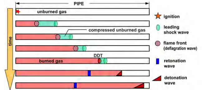
Concerning the deflagration, two main phenomena affecting the pipe wall, have to be distinguished, so-called leading shock waves (pre-shocks) and the flame front. The leading shock waves are initiated continuously due to the heat release and piston effect of the flame and are running through the pipe ahead of the flame front, Fig. 1. This means that after the leading shock formation the flame propagates through pre-compressed and pre-heated unburned gas.
In their first stage directly after the ignition the leading shocks are generated by a spherical quasi-laminar flame and propagate approximately with the speed of sound of the unburned gas through the pipe. In later stages turbulence-generating structures (e. g. wall friction or weld seams) as well as the compressed and heated unburned gas lead to an acceleration of the flame front with correspondingly advanced formations of shock waves. When the heated and compressed unburned gas ahead of the flame front reaches the conditions for a detonation the deflagration jumps into detonation. This is called deflagration to detonation transition (DDT). The detonation starts as a so-called overdriven detonation in the volume of the compressed and heated gas. Hence the overdriven detonation can show a multiple pressure comparing with the following (stable) Chapman-Jouguet (CJ) detonation, which is based on the filling (operating) pressure only. It should be noted that the gas reactions of the phase of deflagration and its transition to the detonation is very complex and not definitely resolved until now.
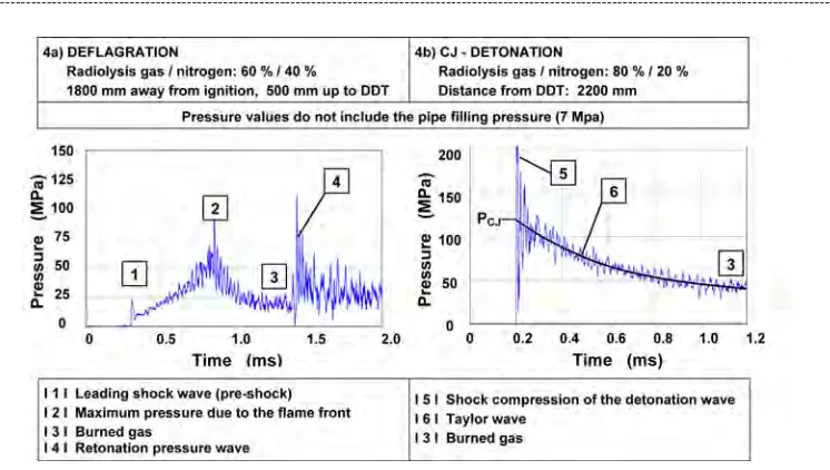
The pressure profile of a stable CJ-detonation, Fig. 2, is characterized by the jump to the CJ
-pressure peak PCJ followed by the expansion of the Taylor wave (Taylor, 1950) with decreasing
pressure up to the pressure of the burned gas P3. At DDT the expansion of the Taylor wave is
infinitesimal, but increases with increasing propagation of the detonation.
At the time of DDT a pressure wave propagates additionally and in contrary direction to the detonation back through the burned gas due to the conservation of momentum. This pressure wave is called retonation (see Fig. 1).
Figure 2. Detonation wave under the idealization of a Chapman-Jouguet Detonation (schematically).
4
PIPE TESTS WITH RADIOLYSIS GAS DETONATION
Detonation tests were performed at the Materialprüfungsanstalt (MPA) Universität Stuttgart to simulate detonations of radiolysis gas (RG) with and without the presence of steam in piping (Roos, 2007). The radiolysis gas was simulated by a mixture of hydrogen and oxygen in its stoichiometric ratio and nitrogen was used to simulate the steam. Volume parts of radiolysis gas in the range of 50 % up to 80 % were ignited in the pipes. Straight seamless pipes up to lengths of 6 m as well as pipes with a welded elbow and flange were used as test material. These thin-walled pipes were made of stainless
steel (X10CrNiTi18-9) in the dimensions of O.D. • t = 114.3 mm • 6.02 mm and the filling pressure
was 7 MPa according to the operating pressure of a special BWR-piping. A burst membrane to simulate an open-ended pipe closed the end of the pipes.
Pressure sensors with a capacity of 600 MPa were applied to the flanges at the pipe ends. The pipes themselve were instrumented by strain gauges and patterns for optical deformation measurements. The patterns were recorded together with the fracture development of the pipe by a high-speed camera (Photron APX-100). By using optical deformation analysis based on the raster method (ARAMIS), it was possible to evaluate global and local strains and deformations up to the level of the fracture initiation. The tests were carried out at room temperature in the underground test pit of MPA in cooperation with Pro-Science GmbH, Ettlingen (Germany). In this test pit with a depth of 32 m and a diameter of 14 m it was possible to carry out tests in safe manner up to combustion heats of the radiolysis gas of about 13000 kJ.
In order to dimension the detonation tests with the thin-walled pipes described above and to obtain pressure profiles for the numerical simulations, tests with thick-walled quasi-rigid pipes with an inner diameter of 36 mm and a length of 4 m were carried out first. These tests with exclusion of bursting were instrumented by pressure sensors over the whole pipe length and were performed in cooperation with Pro-Science GmbH using a testing facility of the Karlsruhe Research Center (FZK). Elementary pipe load parameters like run-up distance, wave velocities and pressure-time history were obtained from these tests in dependence of the volume proportion of radiolysis gas to nitrogen in the range between 40/60 and 100/0.
5
QUASI-STATIC PIPE TEST
For the demonstration of the different pipe behaviour under quasi-static or dynamic pressure loading respectively a quasi-static burst test (pressure medium water) was carried out first, Fig. 3.
6
RESULTS OF THE TESTS WITH QUASI-RIGID PIPES
The objective of the detonation tests with the quasi-rigid pipe (I.D. = 36 mm, O.D. = 133 mm) was to determine experimentally pipe loading parameters in dependence on the volume part of radiolysis gas inside the pipe. Of interest was the deflagration with its run-up distance (RUD) as well as the detonation, the retonation and the reflection at the rigid pipe end (see section 3).
Fig. 4 shows exemplarily two pressure measurements, Fig. 4a is referring to the phase of the deflagration and Fig. 4b to the phase of the detonation. Fig. 4b demonstrates additionally the
determination of the PCJ-value by fitting the Taylor wave by a mathematical function. The pressure
measurement at the detonation front is characterized by high oscillations, which are typical and well known from high dynamic processes like the shock compression at the detonation front. The main results of the tests with detonation inside quasi-rigid pipes can be summarized as follows.
---
Volume part of Number CJ-pressure Detonation velocity Run-up distance
radiolysis gas of tests PCJ (MPa) DCJ (m/s) RUD (mm)
---
100 % 1 1370 approx. 3100 110
80 % 2 1300 approx. 2700 160 up to 180
60 % 3 1) 1) 1400 up to 2300
40% 1 no detonation occurred over the pipe ≥ 4000
length of 4000 mm
1) No CJ-detonation could be definitely determined. The detonation was interpreted as an
overdriven detonation whose transition to the stable CJ-detonation did not definitely
occur over the given pipe length of 4000 mm.
---Figure 4. Exemplary pressure measurements. 4a) Deflagration phase 4b) Detonation phase
7
RESULTS OF THE TESTS WITH THE THIN-WALLED PIPES
Altogether 6 detonation tests were carried out with thin-walled straight pipes, relevant in practice, Fig. 5, and one test with a pipe with elbow and flange. Based on the results of the tests with the
quasi-rigid pipe a pipe length of 1.8 m was chosen for the first test V80E1 with 80 % radiolysis gas
rupture at a distance of about 2.4 m from the point of ignition. The other pipe (V80E3) showed no bursting. It can be assumed that both pipes attained their maximum strain capability with the determined diameter widening between 34 % (V80E2) and 37 % (V80E3). Some possible reasons for the different pipe behaviour are described below.
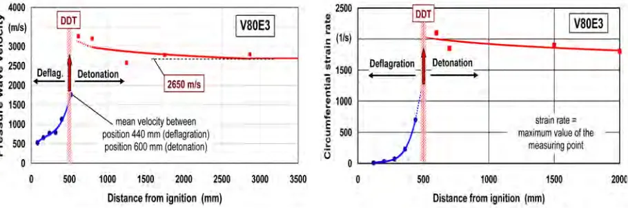
According to Fig. 6 and Fig. 7 the DDT-point of both pipes (V80E2 and E3) was determined at a distance of about 500 mm from the point of ignition. This value corresponds to the run-up distance. The point of DDT is characterized by a spontaneous jump of the deflagration wave velocity to the higher velocity of the detonation wave. A short and negligible time after DDT the strain rate in
circumferential pipe direction also shows a jump-like increase up to values of 2100 s-1 close to DDT
and of about 1800 s-1 at a larger distance from DDT. The higher strain rate can be attributed to the
overdriven detonation (see section 3) and the lower strain rates near the pipe end to the (stable) CJ-detonation. The effect of the overdriven detonation and the retonation (see Fig. 1) can be described more demonstratively by the diameter widening, Fig. 8. Particularly pipe V80E3 shows a hump in the region of DDT. The following decrease of the diameter widening is caused by the decrease of the
maximum pressure of the overdriven detonation to the PCJ-value. Then the diameter widening
increases again due to the increasing expansion of the Taylor wave of the (stable) CJ-detonation. The hump of the diameter widening of the pipe V80E2 could not develop equally to V80E3 due to the quasi-rigid and corset-like sleeve at the ignition side (see Fig. 5 and 7). The larger deformation and higher volume of pipe V80E3 in the region of DDT may have caused a faster decrease of the maximum detonation pressure resulting in a shorter Taylor wave. Due to this effect, the decrease of the diameter widening occurred over a larger pipe length compared to the pipe V80E2 (see Fig. 8) and the following increase of the diameter widening up to the value responsible for the bursting will be attained later. Additionally the earlier bursting of the pipe V80E2 may be caused by the measured differences in the diameter and wall-thickness of the pipe V80E2 due to the normal tolerances of the fabrication.
Figure 6. Determination of DDT at the Figure 7. Determined strain rates at the
example of the pipe V80E3. example of the pipe V80E3.
Figure 8. Diameter widening of the pipes V80E2 and V80E3 after the test.
The pipes with 60 % radiolysis gas detonation showed a different deformation and bursting behaviour in comparison with the pipes in which 80 % radiolysis gas was ignited (see Fig. 5). The bursting occurred in a very short distance from DDT. This means that the bursting was caused by the overdriven detonation and not by the (stable) CJ-detonation as in the test V80E2. Although the volume part of radiolysis gas was less than in the test V80E2 the detonation energy release rate (energy excursion) in the initial phase of the bursting was definitely higher in the tests with 60 % radiolysis gas. This statement is demonstrated by the determined strain rates of the pipe wall which attained
values up to 3300 m s-1 against 2100 m s-1 in case of the 80 % radiolysis gas detonation. Further
indications are the multiple longitudinal crack initiation and propagation, Fig. 9, as well as the partly very small and shell splinter like fracture pieces (see Fig. 5). The fact that the bursting occurred in the region of the overdriven detonation and not until the transition to the CJ-detonation (V80E2) may be explained by the phenomenon that the length of the pre-compressed unburned gas (see section 3) and with this the propagation length of the overdriven detonation increases with
Figure 9. High speed film documentation of the bursting of pipe V60E1 (60 % RG, 40 % N2)
increasing run-up distance. In case of the tests V60E1 and V60E2 the cross section of DDT was determined at a distance of about 3900 mm and 3500 mm respectively from the ignition, whereas the corresponding value of the tests with 80 % of radiolysis gas is about 500 mm. The distance from the undestroyed part of the pipes V60E1 and V60E2 up to the cross section of DDT can be primarily attributed to the retonation. At the end of the undestroyed pipe length a maximum diameter widening of 18 % was measured after the tests V60E1 and V60E2.
A further remarkable result of all tests with pipe bursting is that the pressure profile of the detonation wave was still completely developed at the end of the pipes. This means that the pipe bursting did not influence the further propagation of the detonation or only in a negligible manner.
Concerning the tests with 50 % radiolysis gas (50 % nitrogen) no detonation and hence no bursting occurred over the pipe length of 6 m. The only gas reaction was deflagration. Correspondingly the maximum diameter widening was measured with about 3 % only.
In the tests with quasi rigid pipes (see section 6) which were additionally prepared with boreholes for the pressure sensors, shorter run-up distances were determined compared to the tests with the thin-walled practice related pipes (80 % RG: 170 mm / 500 mm, 60 % RG: 1400 up to 2300 mm / 3500 up to 3900 mm). This result may be explained among other things with the pipe diameter (I.D. 36 mm / 102 mm), the turbulence-generating effect of the boreholes of the quasi-rigid pipes and the plastic deformation capability of the thin-walled pipes.
8
SOME RESULTS OF THE NUMERICAL INVESTIGATIONS
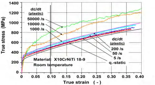
For the description of the pipe behaviour under radiolysis gas detonations by numerical methods first of all a material constitutive law has to be chosen considering the material behaviour primarily as a function of strain, strain rate and temperature up to the state of rupture (Offermanns, 2009). The basis for this was the results of small scale specimen tests. Concerning the strain rate dependence high speed
tensile tests were carried out up to strain rates of 1000 s-1, dynamic compression tests up to 2500 s-1
and split-Hopkinson pressure bar tests (SHPB) for strain rates up to 5·104 s-1. Some results of these
tests are shown in Fig. 10.
Figure 10. Results of small scale specimen tests describing the strain rate dependence of the material
The detonation tests were simulated by a finite-element analysis using the Johnson-Cook material model. The calculations were performed by the explicit FE-code ABAQUS/Explicit using axisymmetric solid elements (Offermanns, 2009).
Regarding the 80 % radiolysis gas detonation, Fig. 11 shows the result of the numerically determined pipe behaviour in comparison with the final deformation of the tested pipe V80E3. There is a good agreement between the FE-calculation and the test. Additionally a first parameter study was carried out concerning the influence of the wall-thickness of the pipe. The development of a failure criterion considering the special dynamic processes and phenomena is in work. As soon as this criterion is available, it will be possible to assess the distance of the pipe bursting from the DDT cross section for a given (defined) wall-thickness.
Figure 11. Comparison between experimentally and numerically determined pipe behaviour
under radiolysis gas detonation (80 % radiolysis gas, filling pressure 7 MPa).
9
CONCLUSIONS
The tests with radiolysis gas detonations inside of the pipes, O.D. • t = 114.3 mm • 6.02 mm, material
X10CrNiTi18-9, gas filling pressure 7 MPa, lead to the following conclusions:
Using a mixture of 50 % radiolysis gas and 50 % nitrogen, no detonation and consequently no bursting occurred over the tested pipe length of 6 m.
In case of 80 % radiolysis gas (20 % nitrogen), one pipe showed no bursting over a length of about 3.8 m but a diameter widening of 37 % in a distance of about 0.6 m from the ignition. This maximum pipe deformation was caused by the overdriven detonation which started in a distance of about 0.5 m from the ignition. In contrast, a second pipe showed bursting in a distance of about 2.4 m from the ignition due to a (stable) CJ-detonation and a diameter widening of 34 %. Considering the scattering of results, pipe bursting can be postulated in the region of the overdriven (starting) detonation too.
Based on first finite-element calculations it can be assumed, that bursting of the tested pipes may be excluded in case of an 80 % radiolysis gas detonation wave and pipe lengths less than 3.5 m, if the pipes are carried out with a wall-thickness of for example 8 mm instead of 6 mm as tested. However, these calculations have still to be verified by experiments.
In case of 60 % radiolysis gas (40 % nitrogen), at both tested straight pipes the deflagration to detonation transition (DDT) was determined in a distance of about 3.5 m and 3.9 m from the ignition. The pipe bursting was caused by the overdriven detonation. Although the volume part of radiolysis gas (60 %) was less than in the tests with 80 % radiolysis gas the energy release rate (energy excursion) was definitely higher in the area of the pipe bursting. It can be assumed that a wall-thickness of 8 mm (tested wall-thickness 6 mm) will also not be able to resist this local detonation energy.
REFERENCES
Kuznetsov, M., Breitung, W., Grune, J. and Singh, R.K., 2005. Sructural response of DN15-tubes under radiolysis gas detonation loads for BWR safety applications. SMiRT 18-J09-1, Beijing, China.
Kuznetsov, M. et al, 2007. Plastic deformation and tube rupture under radiolysis gas detonation loads. Proceedings of ICONE15, Nagoya, Japan, 2007, ICONE15-10377, P 1-12.
Offermanns, S., Roos, E. and Stadtmüller, W., 2009. Structural response of thin-walled austenitic
pipes to radiolysis gas detonations. 9th International Conference on the Mechanical and Physical
Behaviour of Materials under Dynamic Loading (DYMAT), Brüssel, Belgien, 2009.
Redlinger, R., 2007. DET3D - A CFD tool for simulating hydrogen combustion in nuclear reactor safety. Nuclear Engineering and Design 238 (2008), P 610-617.
Roos, E. and Mayer, U., 2003. Progress in testing sheet material at high strain rates. J. Pys. IV 110 (2003), P 495.
Roos, E., Offermanns, S. and Stadtmueller, W., 2007. Investigations on Tube Behaviour under
Radiolysis Gas Detonations. 33rd MPA-Seminar, Universität Stuttgart, 2007.
Schulz, H., Voswinkel, A. and Reck, H., 2002. Eurosafe, forum for nuclear safety, Berlin 2002, GRS/IRSN.
Shepherd, J.E., 2006. Structural response of piping to internal gas detonation. Proceedings of PVP2006-ICPVT-11, Vancouver BC, Canada.