249
Computational Analysis
of Enhanced Cooling
Performance and Pressure
Drop for Nanofluid Flow
in Microchannels
Clement Kleinstreuer, Jie Li, and Yu Feng
9
CONTENTS
9.1 Background Information ...250
9.1.1 Introduction ...250
9.1.2 Review of Experimental Evidence ... 251
9.1.3 Review of Computational Analyses ... 253
9.1.4 Mixture Viscosity Models ...254
9.2 Theory ...254
9.2.1 Governing Equations ...254
9.2.2 Mixture Properties ... 256
9.2.2.1 Effective Dynamic Viscosity ... 256
9.2.2.2 Effective Thermal Conductivity ... 258
9.2.3 Entropy Generation ... 263
9.2.4 Thermal Performance Comparisons ...264
9.2.5 Numerical Method ...264
9.3 Results and Discussion ...265
9.3.1 Flow Friction Validation Studies...265
9.3.2 Convective Heat-Transfer Validation Results ...266
9.3.3 Friction Factor and Pressure Drop Results ...266
9.3.4 Convective Heat Transfer ...269
9.3.5 Entropy Generation ...269
9.4 Conclusion ... 271
Acknowledgment ... 273
9.1 BACKGROUND INFORMATION 9.1.1 IntroductIon
High rates of heat transfer in mechanical, chemical, and biomedical microsystems require heat exchangers which are very small, light, and efficient. Microchannels made out of glass, silicon, or polymers form the basic elements of such microsystems. Improving the thermal performance of compact devices requires better coolants than conventional fluids such as oil, water, or ethylene glycol. One solution to microscale cooling problems is the addition of solid nanoparticles to the fluid. The resulting
nanofluids, that is, dilute suspensions of nanoparticles in liquids, may significantly change the mixture’s properties, most notably its thermal conductivity and viscosity.
Nanoparticles considered for microsystem cooling range from metals and metal oxides to carbon nanotubes with diameters of 1–100 nm. Indeed, prevailing experi-mental evidence indicates a greater enhancement of nanofluid thermal conductivity,
knf, than predicted by the “effective medium” theory of Maxwell [1] or Hamilton and Crosser [2]. Such an increase of knf over kbase-fluid varies with nanoparticle vol-ume fraction and characteristics, for example, size, shape, material, surface charge/ coating, and degree of particle aggregation, as well as with the type of base fluid, its temperature, conductivity, pH value, and additives. Nevertheless, although in the past-enhanced knf values have been reported when employing the transient hot-wire method, some data based on recent nonintrusive (optical) techniques could not confirm such high knf values, or even an increases over the values obtained with Maxwell’s theory. Clearly, additional studies are warranted.
For a better understanding of the underlying physics of knf enhancement, six major sources should be considered: (i) micromixing because of Brownian motion of the nanoparticles affecting the surrounding fluid, (ii) higher pathway conduction of clustered nanoparticles or connected carbon nanotubes, (iii) liquid–molecule lay-ering around nanoparticles causing lower heat resistance, (iv) larger heat conduction in the case of certain metallic nanoparticles, (v) thermal wave impact, and/or (vi) nanoparticle and wall–shear-layer interactions.
Experimental observations and theoretical models of nanofluid thermal con-ductivity enhancement have been critically reviewed by Kleinstreuer and Feng [3], Oezerinc et al. [4], Fan and Wang [5] as well as by Murshed et al. [6] and Timofeeva et al. [7], whereas heat-transfer applications with nanofluids as coolants are discussed in books by Das et al. [8], Li [9], and Kumar [10]. Kleinstreuer and Feng [3] focused on the review of knf measurement techniques and theoretical models. Comparing the-oretical predictions and experimental findings of knf values, Oezerinc et al. [4] reit-erated that significant discrepancies exist. Fan and Wang [5] provided an overview of recent contributions discussing thermal conductivity enhancement of nanofluids. They tabulated experimental observations for carbon nanotubes and nanospheres in different base liquids. Of the various theoretical models discussed, they favored the recently developed thermal wave theory with which experimental findings can be apparently modeled and explained. Murshed et al. [6] as well as Timofeeva et al. [7] took a more comprehensive view of nanofluids, evaluating nanoscale contributions to both mixture properties and engineering applications.
First, some representative experimental and numerical papers concerning possi-ble knf enhancement are reviewed. Then, the computational development and cooling application of nanofluid flow in a microchannel is discussed to illustrate the impact of different thermal conductivity and effective viscosity models on convection heat transfer and pressure drop. Reduction of entropy generation for this fundamental test case is provided as well.
9.1.2 revIewof experImental evIdence
Numerous experimental studies on nanofluid single-phase heat transfer have been reported in the literature. Most of these relied on the transient hot-wire method to measure thermal conductivity and/or indirectly Nusselt number values. For example, Pak and Cho [11] investigated alumina–water and titania–water nanofluids in turbu-lent convective heat transfer in tubes. Xuan and Roetzel [12] conveyed a heat–trans-fer correlation for nanofluids to capture the effect of energy transport by particle “dispersion.” Wen and Ding [13] studied laminar nanofluid convective heat transfer and reported significant enhancement in the entry region. Heris et al. [14,15] ana-lyzed the effects of alumina and copper oxide nanofluids on laminar heat transfer in a circular tube under constant wall temperature boundary condition. They reported an enhancement of the heat-transfer coefficient for both nanofluids with increas-ing nanoparticle concentrations as well as the Peclet number, and observed a larger enhancement for alumina than for copper oxide.
Buongiorno [16] suggested that a reduction of viscosity within the boundary layer and consequent thinning of the laminar sublayer lead to an abnormal increase in the convective heat-transfer coefficient in the turbulent flow regime. Jung et al. [17] measured the convective heat transfer and friction factor of nanofluids in rectangu-lar microchannels. Nanofluids with 170-nm aluminum dioxide particles and with various particle volume fractions were used in their experiments. For a volume frac-tion of 1.8%, a 320% convective heat transfer increase in the laminar regime was measured compared with distilled water, without major frictional loss. They also found that the Nusselt number increases with the increasing Reynolds number in the laminar flow regime, which is contradictory to the result from conventional thermal Poiseuille-flow analysis.
Rea et al. [18] experimentally investigated laminar convective heat transfer and viscous pressure loss for alumina–water and zirconia–water nanofluids in a flow loop with a vertical heated tube. Their measured heat-transfer coefficient and pressure loss were in good agreement with the traditional model predictions for laminar flow; in other words, there was no abnormal heat-transfer enhancement or pressure loss observed within the measurement error.
Vajjha et al. [19] presented new correlations for the convective heat-transfer coefficient and friction factor developed from the experiments with different nano-fluids assuming fully developed turbulent flow. Khiabani et al. [20] considered the impact of cylindrical particles on the heat transfer in a microchannel based on the solution of the lattice-Boltzmann equation for fluid flow, coupled with the energy equation for thermal transport and the particle dynamics equations for
direct simulation of suspended particle transport. They found that each particle can locally enhance heat transfer, and hence the average heat-transfer perfor-mance can be improved. Hojjat et al. [21] experimentally investigated convective heat transfer of non-Newtonian nanofluids through a uniformly heated circular tube under turbulent flow conditions, noting again heat-transfer enhancement of such nanofluids. Considering Al2O3–ethylene glycol (EG) nanofluids, Hemalatha et al. [22] found experimentally that above a weight percentage of 0.6, particle– particle interactions may be important due to particle aggregation. Escher et al. [23] found that mixture properties of silica–water nanofluids, even at high con-centrations (i.e., up to 31%), did not deviate more than 10% from the effective medium theory established by Maxwell. Furthermore, they demonstrated that any relative knf enhancement must be larger than the relative viscosity increase in order to gain effective cooling performance with nanofluid flow in micro-channels. In a combined experimental and theoretical study, Gharagozloo and Goodson [24] analyzed temperature-dependent nanoparticle aggregation and dif-fusion. They concluded that aggregation produces an unfavorable nanofluid for heat transfer and suggested an optimal nanoparticle diameter of 130 nm for mini-mizing aggregation, sedimentation, and thermal diffusion. In order to illuminate potential causes of experimental uncertainties, such as nanoparticle aggregation effects or “time-dependent nanofluid characteristics,” Xie et al. [25] summarized numerous experimental data sets for oxide and carbon–nanotube nanofluids in different liquids. They recommended that extra care should be taken in prepar-ing homogeneous and stable mixtures, notprepar-ing that additives such as acid, base, and/or surfactants are influential. They observed that knf enhancement increases monotonously with nanoparticle loading, whereas the temperature effect on nano-fluids largely depends on the type of nanoparticle and base fluid pairing. A recent study by Lee et al. [26] introduced round-robin tests on thermal conductivity mea-surements of three samples of EG-based ZnO nanofluids. The experiments were conducted in five laboratories, where four of them used measurement appara-tuses developed in house and one used a commercial device. On the basis of their results, the conventional thermal conductivity model underestimates the effective thermal conductivity of nanofluids. Thus, the effective thermal conductivity of nanofluids cannot be fully explained by the effective medium theory for well-dispersed nanoparticles.
Recently, several research groups attributed convective heat-transfer enhance-ment to the interactions of nanoparticles and the system/device walls (see [27–30]). Specifically, the random fluid-particle velocity field in the wall boundary layer is changed due to the interaction of nanoparticles with the channel walls as well as the surrounding fluid parcels. It may steepen the mixture temperature profile and hence lead to a large temperature gradient near the wall, resulting in a higher heat transfer rate. For example, Hwang et al. [27] measured the pressure drop and con-vective heat-transfer coefficient of water-based alumina nanofluids flowing through a uniformly heated circular tube in the fully developed laminar flow regime. They discussed the various parameter effects on the remarkable enhancement of the con-vective heat transfer coefficient and showed for the first time the flattened core velocity profile.
9.1.3 revIewof computatIonal analyses
To investigate heat transfer enhancement by nanofluids computationally, two main approaches have been adopted in the literature. The first one is the two-phase model that takes into account the fluid- and solid-phase roles in the heat transfer process. The second one is the single-phase model where both the fluid phase and the solid particles are in a thermal equilibrium state and flow with the same local velocity. The second approach is simpler and requires less computational time. Also, if the main interest is focused on the heat-transfer process, the modified single-phase approach is more convenient than the two-phase model. For example, based on computational fluid dynamics (CFD) simulations, Fard et al. [32] found that the two-phase approach generates better predictions of nanofluid convective heat transfer compared with the single-phase model, Lofti et al. [33] numerically investigated convective heat trans-fer of nanofluids in horizontal tubes using a single-phase model and a two-phase mixture model as well as the two-phase Eulerian model. The comparison of calcu-lated results with experimental values indicated that the two-phase mixture model was more precise.
Heyhat and Kowsary [34] investigated numerically the effect of nanoparticle migration on the flow pattern and convective heat transfer in a circular pipe. They claimed that the nonuniform nanoparticle distribution led to a higher heat-transfer coefficient while the wall shear stress decreased. Akbarina et al. [35] considered alumina–water nanofluid flow in two-dimensional rectangular microchannels to study heat-transfer enhancement due to the addition of nanoparticles to the base fluid, especially at low Reynolds numbers. They found that for a given Reynolds number, the major enhancement in the Nusselt number was not so much caused by higher nanoparticle concentrations but mainly due to an increase in flow rate to reach a set Reynolds number. Hence, constant Reynolds number studies of nano-fluid flow may be insufficient when evaluating the heat-transfer characteristics. Kondaraju et al. [36] focused on deviations in experiments concerning the effec-tive thermal conductivity of polydisperse nanoparticles. Both the initial particle distribution and any inhomogeneous coagulation were found to be major factors in the determination of effective thermal conductivity results for multisize particles in nanofluids. Concerning nanoparticle aggregation, Werth et al. [37] analyzed differ-ent particle forces leading to agglomeration of charged nano-powders. Jiang et al. [38] developed a model for the prediction of nanoparticle aggregation and sedimen-tation. Focusing on nonspherical nanoparticles, Evans et al. [39] employed Monte Carlo simulations and determined a positive impact of aggregation on the effective thermal conductivity.
For microchannel heat-sink applications, Li and Kleinstreuer [40] analyzed entropy generation of pure water and CuO–water nanofluid flow in trapezoidal microchannels. Similarly, Singh et al. [41] investigated the entropy generation of nanofluids due to flow friction and heat transfer for alumina–water nanoflu-ids in tubes of three different diameters. An alternative approach to assuming that a nanofluid is a homogeneous mixture, Kalteh et al. [42] proposed Eulerian– Eulerian two-phase simulations to compute possible heat-transfer enhancement in microchannel flow.
9.1.4 mIxture vIscosIty models
Clearly, coarse and even fine particles added to liquid coolants (before the advent of nanofluids) may measurably increase the mixture’s effective viscosity, which relates to high pumping power, sedimentation, and filter clogging. So, parallel to improved heat-transfer performance when using nanofluids, mixture viscosity data and models have to be considered. Focusing on viscosity models for nanofluids, Pak and Cho [11], for example, selected 13-nm alumina nanoparticles in water with volume fractions, φ, from 1.33 to 2.86% and measured μeff / μbf values ranging from 1.63 to 2.6. In contrast, Wang et al. [43] recorded significantly lower viscosity ratios (i.e., 1.12–1.88 when 1.02 < φ < 5%) for a 28-nm Al2O3–water mixture. More recent experimental studies (see [44–46] among others) confirmed the nonlinear dependence of the effective mix-ture viscosity on various mixmix-ture parameters. Thus, earlier correlations proposed by Einstein [47] and improved upon by Brinkman [48], Batchelor [49], and Graham [50], which included only the nanoparticle volume fraction, have to be revisited. For exam-ple, Koo and Kleinstreuer [51] suggested μeff = μstatic + μBrownian, where the viscosity enhancement due to Brownian nanoparticle motion is a function of knf/kbf, μbf, and the Prandtl number. Similarly, Masoumi et al. [52] postulated that μeff is the sum of μbf plus an apparent viscosity which is mainly caused by Brownian motion. Traditionally, the wall roughness of microchannels also contributes to an increase in friction fac-tor and hence the required pumping power; however, more modern fabrication tech-niques may keep the (or result in) relative surface roughness typically below 0.5%.
9.2 THEORY
For the selected test case, it is assumed that the continuum hypothesis is valid, that is, the channel hydraulic diameter Dh > 100 μm (see Chapter 7 in ref. [53]). Thus, for steady three-dimensional laminar incompressible nanofluid flow in a microchannel, the continuity, momentum, energy, and species mass transfer equations have to be solved, considering temperature and volume-fraction-dependent mixture properties. In addition to the conservation laws and models for the mixture properties, the sec-ond law of thermodynamics has to be formulated for system optimization via reduc-tion in entropy generareduc-tion rate.
9.2.1 GovernInG equatIons Continuity:
∂
∂xi ui =
(ρ ) 0 (9.1)
Momentum:
u
x u
p
x x
u x
u x j
j i i j
i j
j i
∂
∂ = − ∂∂ + ∂∂ ∂ +∂ ∂ ∂
(ρ ) µ (9.2)
Energy (within fluid):
u c T
x x k
T x i
i i i
∂ ∂
= ∂∂ ∂∂ + (ρ )
µ
p
Φ (9.3)
where the dissipation function reads:
Φ = ∂∂ + ∂∂
∂ ∂
u x
u x
u x i
j j i
i j
(9.4)
Energy (within solid):
k T
xi
s∂
∂ =
2
2 0 (9.5)
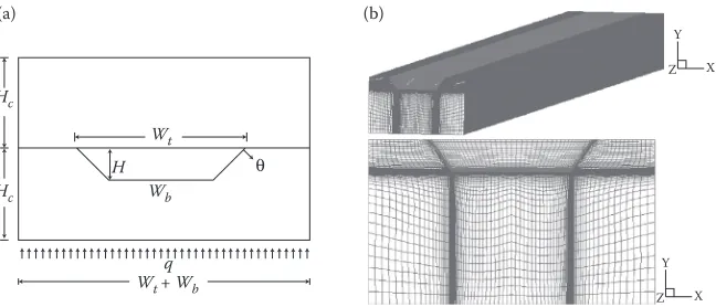
For nanofluid flow and pure fluid flow, the corresponding physical properties are the density, thermal conductivities knf and kbf and the viscosities μnf and μbf, respectively (see Section 9.2.2). The thermal conductivity of the silicon microchan-nel wall ks was assumed to be constant. Uniform velocities were applied at the chan-nel inlet, that is, u = 0, v = 0, w = Uin to simulate any entrance effect. Exposed to the atmosphere, the outlet pressure was the static pressure, that is, pgage = 0. The no-slip boundary condition was enforced at all solid walls. The thermal boundary condition at the bottom was a constant wall heat flux, whereas an adiabatic boundary condition is imposed on the top wall, symmetric boundary condition at the two side walls, and
T = T0 at the microchannel inlet. These thermal boundary conditions (see Figure 9.1) are standard assumptions, where the channel-cover functions as a perfect insulator while the sidewalls of the machined or edged microchannel are equally exposed to the heat source, expressed as a constant wall-heat flux.
(a) (b)
Wb
q
H θ
Y
Z X
Y
Z X
Wt+ Wb Wt Hc
Hc
FIGURE 9.1 (a) Typical microchannel heat sink element and (b) finite volume mesh.
The models for the nanofluid properties, μnf and knf, are outlined in Section 9.2.2 and balance equations for entropy generation are discussed in Section 9.2.3, while the performance indicators are given in Section 9.2.4.
9.2.2 mIxture propertIes
The basic nanofluid properties are a function of nanoparticle volume fraction φ and mixture temperature T. Such nanofluids are assumed to be dilute suspensions, that is, the homogeneous, noninteracting nanoparticles are well dispersed. Specifically, for dilute Al2O3–water nanofluids [54]:
ρnf = ϕρp + −(1 ϕ ρ) bf (9.6)
(ρcp nf) =ϕ ρ( cp p) + −(1 ϕ ρ)( cp bf) (9.7)
where the subscripts nf, bf, and p indicate nanofluid, base fluid, and particle, respec-tively, ρ is the density, cp is the specific heat capacity, φ is the nanoparticle volume fraction.
The properties of the base fluid (water) are assumed to be temperature-dependent [54]:
ρwater = − +
⋅ − −
1000 1 15 7914
508 929 2 205 0204 277 13
( . )
, . ( . )( .
T
T T 663
2
)
(9.8a)
c T
T
p,water = − ⋅
+ ⋅ −
9616 873445 48 73648329 0 1444662 2 0 000141
. .
. .
4414⋅T3 (9.8b)
µwater = 0 02165 0 0001208. − . ⋅ +T 1 7184. e− ⋅7 T2 (9.8c)
kwater = −1 1245 0 009734. + . ⋅ −T 0 00001315. ⋅T2 (9.8d)
where T = T/( [ ])1K is the nondimensional temperature. 9.2.2.1 Effective Dynamic Viscosity
Most of the reported data for nanofluid viscosities have been discussed in terms of formulations proposed by Einstein [47], Brinkman [48], Batchelor [49], and Graham [50], to name a few. The conventional viscosity models of nanofluids are summa-rized in Table 9.1. It turns out that none of the models mentioned can predict the viscosity of nanofluids very well for a wide range of nanoparticle volume fraction.
Nguyen et al. [55] investigated experimentally the influence of both the tem-perature and the particle size on the dynamic viscosity for two nanofluids, that is,
Al2O3–water and CuO–water combinations. More recently, employing a differ-ent measuremdiffer-ent technique, Chandrasekar et al. [31] got similar viscosity data for Al2O3–water nanofluids.
Abu-Nada [56] performed a two-dimensional regression on experimental data of Nguyen et al. [55] and developed the following relation of viscosity in centi-poise as a function of the nondimensional temperature T and volume fraction φ, which had a
maximum error of 5%.
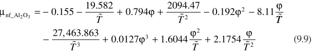
µnf_Al O2 3 = −0 155− + ϕ+ − ϕ − ϕ
19 582 0 794 2094 47 0 192 8 11
2
2
. . . . . .
T T TT
T T T
− 27 463 8633 +0 0127 3+1 6044 2 +2 1754
2
, .
. . .
ϕ ϕ ϕ (9.9)
Masoumi et al. [52] proposed a new model by including the effect of Brownian motion of the nanoparticles on the viscosity of nanofluids in terms of μnf = μ bf + μapp, where μapp is the apparent viscosity defined by Masoumi et al. [52]. Temperature, nanoparticle diameter, volume fraction, nanoparticle density as well as the base fluid physical properties were all considered.
µnf µbf ρ δ p B p
= + 72v dC 2 (9.10)
where vB =(1/dp) (18κbT/πρp pd ) is the Brownian velocity, κb is the Boltzmann constant, δ = 3(π ϕ/6 )dp is the distance between nanoparticles, C = fct(μbf, dp, φ) is the correction factor.
TABLE 9.1
Conventional Viscosity Models for Nanofluids
Model Expression Comments
Einstein
[47] µnf =µbf(1 2 5+ . )ϕ
Spherical particles and low-volume fraction, that is, φ< 2%
Brinkman
[48] µnf = (1−µϕbf)2 5.
Extended Einstein expression
Batchelor
[49] µnf =µbf(1 2 5+ .ϕ+6 5. ϕ )
2 Extended Einstein equation
by considering the effect of Brownian motion on the bulk stress
Graham
[50] µnf µbf ϕ
p p p
/ / /
= + + + +
1 2 5 4 5 1
2 1 2
. .
(c d)( (c d))( (c d))
dp is the particle diameter and
c is the inter-particle spacing
The correlation factor C was calculated by using experimental data for water-based nanofluids consisting of 13 and 28 nm Al2O3 nanoparticles as well as the 36 nm Al2O3–water nanofluid by Nguyen et al. [55].
For a better understanding the performance of nanofluids in microchannels, the extended Einstein’s equation by Brinkman [48] and the effective nanofluid viscosity postulated by Masoumi et al. [52] were analyzed. Figure 9.2 compares the two models as a function of volume fraction and three different nanoparticle sizes for the model by Masoumi et al. [52]. As already noticed by Ngugen et al. [55], the conventional Brinkman model (see Table 9.1) underpredicts the nano-fluid viscosity. Furthermore, the functional dependence μnf (φ) is highly nonlin-ear in the model by Masoumi et al. [52], especially for φ> 3% and dp< 40 nm (see Figure 9.2a). Such a viscosity enhancement of nanofluids may increase the pressure drop or the requirement of pumping power. As expected, the tempera-ture influence on μnf (see Figure 9.2b) is much less dramatic, being expressed as μbf (T).
9.2.2.2 Effective Thermal Conductivity
For the thermal performance analysis of nanofluid flow in microconduits, several thermal conductivity models have been employed (see [57] among others). In this chapter, three different models were applied and compared, that is, the conventional Maxwell model, the correlation by Patel et al. [58], as well as the newly developed Feng–Kleinstreuer (F–K) model [57]. Maxwell [1] derived a “static” thermal conduc-tivity model for conventional fluids containing at that time micrometer/millimeter particles. It was assumed that the effective thermal conductivity of the mixture is a function of the thermal conductivity of the suspensions and the base fluid as well as the volume fraction of the suspensions:
k
k k k k
k k
static
p
bf
p
bf
p
bf
= +
−
+
− −
1
3 1
2 1
ϕ
ϕ
kbf (9.11)
The emergence of nanofluids as a new field of nanoscale heat transfer, with appli-cations to microsystem cooling, is directly related to miniaturization trends and nanotechnology. The unexpected high thermal conductivity of nanofluids docu-mented in many experiments showed that the effective thermal conductivity of nanofluids depends not only on the nanostructures of the suspensions but also on the dynamics of nanoparticles in liquid. Kleinstreuer and Feng [57] postulated that the thermal conductivity of nanofluids consists of a static part (kstatic) after Maxwell [1] and a micromixing part (kmm), that is, enhancement due to Brownian motion of nanoparticles. The F–K model can be expressed as
knf = kstatic +kmm (9.12)
0 0.5 1 1.5 2
φ 2.5 3 3.5 4
1 1.1 1.2 1.3 1.4 1.5
Brinkman model (dp = 28 nm, T = 298 K) (dp = 36 nm, T = 298 K) (dp = 47 nm, T = 298 K)
(a)
}
Temperature (°C)
20 25 30 35 40 45 50 55 60
1.1 1.15 1.2 1.25 1.3 1.35 1.4 1.45 1.5
dp = 28 nm
dp = 36 nm
dp = 47 nm
(b)
μnf /μbf
μnf /μbf
Model by Masoumi et al.
FIGURE 9.2 Dynamic viscosity models for nanofluids: (a) viscosity versus volume fraction
and (b) viscosity change with temperature (φ= 4%, model by Masoumi et al. [52]).
The static part is Equation 9.11, whereas the micromixing part, based on sound physics, is given by (see [57])
k
m C c
T T T
mm
B p
p c p nf
n p = ⋅ ⋅ ⋅
( )
⋅ ⋅(
−)
⋅ − 49 500 2 3 2 , ln exp( )sinh κ τ ρ ϕ ζω τ ππµ πµ τ πµ bf p p P P p p bf p p bf p p d m K m m d d m K(
)
− (
)
− − 2 2 2 2 4 3 3 4 PP P p − m (9.13)Here, Cc is equal to 38 for metal oxide nanofluids which can be derived theo-retically (which also holds for the number 49,500), instead of being obtained via a curve-fitting technique [59].The damping coefficient ζ, natural frequency ωn, and characteristic time interval τp can be expressed as
ζ = 32π µmdpωbf
p n
(9.14)
ωn
p
= K − m
P P (9.15)
τp πµ p
bf p
= 3 m d (9.16)
Specifically, for metal oxide nanofluids, the magnitude of particle–particle inter-action intensity KP–P is determined for different particle diameters as
KP P− = ρp dp⋅10−932 1724 273. T⋅ K −19 4849. for20nm < dp ≤ 50nm
(9.17)
K d
T d
P P− = ρp p⋅10−924 6402 273. ⋅ K −18 7592. for p > 50nm (9.18)
In light of experimental evidence, the F–K model is suitable for several types of metal oxide nanoparticles in water with volume fractions up to 5% and mixture temperatures below 350 K.
In contrast, Patel et al. [58] provided a correlation for the effective thermal conduc-tivity of nanofluids, based on a regression analysis of several experimental data sets:
knf = kbf(1 0 135+ . ×(k kp/ bf)0 273. ×ϕ0 467. ×[(T −273 20)/ ]0 547. ×(1000/dp)0 234. )
(9.19)
where T is the temperature of nanofluids in degree Kelvin; dp is the average nano-particle diameter in nanometers. Apparently, the correlation is valid for suspensions of spherical nanoparticles of 10–150 nm diameter, a thermal conductivity range of 20–400 W/mK; base fluids having thermal conductivities of 0.1–0.7 W/mK, particle volume fractions of 0.1–3%, and suspension temperatures from 20°C to 50°C. The model by Kleinstreuer and Feng [57] is based on physical principles without the use of empirical matching factors. In contrast, the knf correlation by Patel et al. [58], hav-ing a much simpler form, is easier to use but lacks physical insight and a broad range of applications.
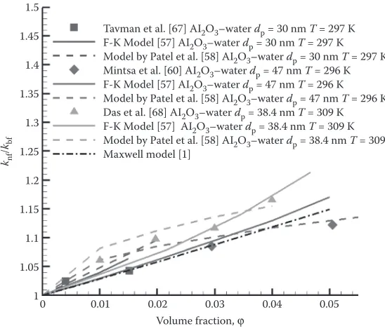
Figures 9.3 and 9.4 compare the F–K model and Patel’s correlation with some recent benchmark experimental data sets. Overall, the F–K model generates a bet-ter matching in trend and precision for different volume fractions and temperatures; although, the measured knf increase with nanoparticle volume fraction above 3% by Mintsa et al. [60] is surprisingly low (see Maxwell model prediction).
1.5
1.45
1.4
1.35
1.3
1.25
1.2
1.15
1.1
1.05
1
0 0.01 0.02 0.03 0.04 0.05
Volume fraction, φ
knf
/
kbf
Tavman et al. [67] AI2O3–water dp = 30 nm T = 297 K
F-K Model [57] AI2O3–water dp = 30 nm T = 297 K
Model by Patel et al. [58] AI2O3–water dp = 30 nm T = 297 K
Mintsa et al. [60] AI2O3–water dp = 47 nm T = 296 K
F-K Model [57] AI2O3–water dp = 47 nm T = 296 K
Model by Patel et al. [58] AI2O3–water dp = 47 nm T = 296 K
Das et al. [68] AI2O3–water dp = 38.4 nm T = 309 K F-K Model [57] AI2O3–water dp = 38.4 nm T = 309 K Model by Patel et al. [58] AI2O3–water dp = 38.4 nm T = 309 K Maxwell model [1]
FIGURE 9.3 Comparison of thermal conductivity models for nanofluids at different volume fractions.
F-K Model [58] AI2O3–water dp = 12 nm φ = 1% Beck et al. [69] AI2O3–water dp = 12 nm φ = 1%
Model by Patel et al. [58] AI2O3–water dp = 12 nm φ = 1%
F-K Model [57] AI2O3–water dp = 38.4 nm φ = 1% Model by Patel et al. [58] AI2O3–water dp = 38.4 nm φ = 1% Chon et al. [70] AI2O3–water dp = 47 nm φ = 1%
Das et al. [68] AI2O3–water dp = 38.4 nm φ = 1%
F-K Model [57] AI2O3–water dp = 47 nm φ = 1% Model by Patel et al. [58] AI2O3–water dp = 47 nm φ = 1% 1.5
(a)
(b) 1.4
1.3
1.2
1.1
1.8
1.7
1.6
1.5
1.4
1.3
1.2
1.1
1 300 310 320 330
Temperature, T (K) 340 350
1 300 320 340
Temperature, T (K)
knf
/
kbf
Model by Patel et al. [58] AI2O3–water dp = 36 nm φ = 3.1% Model by Patel et al. [58] AI2O3–water dp = 38.4 nm φ = 4%
Model by Patel et al. [58] AI2O3–water dp = 47nm φ = 4% Chon et al. [70] AI2O3–water dp = 47 nm φ = 4%
Das et al. [68] AI2O3–water dp = 38.4nm φ = 4%
F-K Model [57] AI2O3–water dp = 36 nm φ = 3.1%
Mintsa et al. [60]AI2 O3–water dp = 36 nm φ = 3.1%
F-K Model [57] AI2O3–water dp = 47 nm φ = 4% F-K Model [57] AI2O3–water dp = 38.4 nm φ = 4%
knf
/
kbf
Mintsa et al. [60] AI2O3–water dp = 47 nm φ = 4% Jung et al. [17] AI2O3–water dp = 47 nm φ = 4%
FIGURE 9.4 Comparison of thermal conductivity models for nanofluids at different tem-perature: (a) small volume fraction and (b) large volume fraction.
9.2.3 entropy GeneratIon
If the mixture is Newtonian and it obeys Fourier’s law of heat conduction, the total entropy generation rate per unit volume (Sgen ≡ SG in W/K × m3) can be expressed as [40]
S S k
T T x T y T z T
gen ≡ G = ∂∂ + ∂∂ + ∂∂
+ 2
2 2 2
2 µ ∂∂ ∂ + ∂∂ + ∂∂ + ∂∂ + ∂ ∂ u x v y w z u y v x
2 2 2
+ ∂ ∂ + ∂∂ + ∂∂ + ∂∂ 2 2 2 u z w x v z w y (9.20)
Equation 9.20 encapsulates the irreversibilities due to heat transfer and frictional effects, that is,
Sgen = Sgen(thermal)+Sgen(frictional) (9.21)
Specifically, the dimensionless entropy generation rate induced by fluid friction can be defined as follows:
S S kT
q
G,F = gen(frictional) 0 2 2 (9.22a) where S T u x v y w z
gen(frictional)= ∂∂ + ∂∂ + ∂∂
µ 2 2 2 2
+ ∂∂ + ∂∂ + ∂∂ + ∂∂ + ∂∂ + ∂∂ u y v x u z w x v z w y 2 2 2 (9.22b)
while for the thermal entropy source, we have
S S kT
q
G,T = gen(thermal) 0 2 2 (9.23a) where S k T T x T y T z
gen(thermal)= ∂∂ + ∂∂ + ∂∂
2
2 2 2
(9.23b)
Finally,
S S kT
q S S
G total, = gen 0 = G,F + G,T
2
2 (9.24)
where T0 is the fluid inlet temperature, and q is the wall heat flux.
In order to assess the overall entropy generated in the entire flow field for different scenarios, the integral form is used:
ˆ
,
S
mc S V
V
G total
p gen
d
= 1
∫∫∫
(9.25)where the fractions of entropy generation due to friction and heat transfer are, respectively:
ξF G,F ξ
G total
G,T
G total
and
= ˆˆ = ˆˆ
, ,
S S
S S
T (9.26a,b)
9.2.4 thermal performance comparIsons
Pumping power is needed to drive the working fluid in microchannels, which is defined as the product of the pressure drop across the channel and the volumetric flow rate:
P = ∆ ⋅p Q (9.27)
In order to compare the thermal performance of nanofluids with pure liquids, the thermal resistance is employed:
θ = Tw ave, q−Tin (9.28)
where Tw,ave is the average wall temperature, Tin is the fluid inlet temperature, and q is the heat added to the microchannel (or the heat removed by the moving fluid).
9.2.5 numerIcal method
The numerical solution of the Eulerian transport equations were carried out with a user-enhanced, unstructured finite-volume-based program, that is, CFX 12.1 from ANSYS, Inc. (Canonsburg, PA). The computations were performed on an IBM Linux Cluster at North Carolina State University’s High Performance Computing Center (Raleigh, NC) and on a local dual Xeon Intel 3.2G Dell desktop (C M-P Laboratory,
MAE Department, NC State University). Mesh independence was examined and verified by increasing the nodal number by 50% which produced a maximum result change of just 1.33% for the velocity and 0.8% for the temperature field. The unstruc-tured mesh for a typical case contained 671,224 hexahedral elements with 631,050 nodes for the fluid domain and 269,486 elements with 247,266 nodes for the solid domain. Figure 9.1 shows the representative geometry and the finite volume mesh we generated. Mesh independence was examined and verified by increasing the nodal number by 50% which produced a maximum result change of just 1.23%. Furthermore, the solutions of the flow field were assumed to be converged when the dimensionless mass and momentum as well as the thermal energy residual ratios were below 10−6. Improving the convergence criteria to <10−7 had a negligible effect on the simulation results. A typical simulation run took about 24 h. Additional model validations were achieved by comparing numerical results of velocity and tempera-ture fields with an analytical solution as well as existing numerical and experimental data sets, as given in Section 9.3.
9.3 RESULTS AND DISCUSSION 9.3.1 flow frIctIon valIdatIon studIes
The Fanning friction factor was used to evaluate viscous effects of flow through micro-channels. The Fanning friction factor f, representing the ratio of fluid shearing strength at the wall to the average kinetic energy of the fluid per unit volume, is defined as
f = ∆pDU Lh
2ρ 2 (9.29)
where Δp is the pressure drop between the inlet and outlet of the microchannel, ρ is the density of working fluid, Dh and L are the hydraulic diameter and the length of the microchannel, respectively, and U is the average fluid velocity.
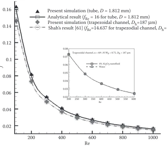
For fully developed channel flow, the friction factor has an inverse correlation with the Reynolds number, that is, fRe should be a constant for a particular geometry. The fully developed velocity profile was first computed using an extended domain upstream, and the outlet velocity profile from this upstream domain was applied as the inlet velocity profile to the primary domain. Adopting the same geometry/aspect ratios and operational parameters, we compared our simulation results with the ana-lytical result for a mini tube (fRe = 16) with diameter of 1.812 mm and the analytical result of Shah [61] for a trapezoidal microchannel, that is, according to Shah [61],
fRe = 14.637 for base angle α= 60°, H/Wb= 0.75. Dh= 187 μm has been used for this validation. As shown in Figure 9.5, the simulation results match the experimen-tal correlations for both mini-tube and trapezoidal microchannel. It is also apparent that for fully developed flow employing 4% alumina–water nanofluid, no measurable increase in the friction factor occurred. Numerically, for the Reynolds number range of 100–1000, fRe = 16.28 ~ 16.29 in the mini-tube and fRe = 14.58 ~ 14.62 for flow in the microchannel; thus, the maximum change is <2%.
9.3.2 convectIve heat-transfer valIdatIon results
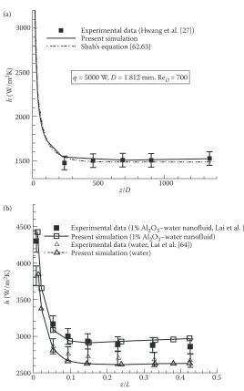
To compare convective heat transfer characteristics, pure water in a mini-tube was investigated. As shown in Figure 9.6a, the present simulation shows a very good match with the experimental data of Hwang et al. [27] as well as the correlation by Shah [62,63]. For an additional validation of the F–K model (see Equations 9.11 through 9.18, and Figures 9.3 and 9.4), its thermal performance of water-based alu-mina nanofluid flow in a 1.02-mm tube was compared with the experimental data of Lai et al. [64]. Employing the same geometry and operational conditions (i.e., a vol-ume flow rate of 5 mL/min), the use of the F–K model generates acceptable results for the local heat transfer coefficient (see Figure 9.6b).
9.3.3 frIctIon factorand pressure drop results
As indicated in Section 9.2, the friction factor and pressure drop as well as the ther-mal performance of alumina nanofluids were computed for a particular trapezoidal microchannel with hydraulic diameter Dh= 194.5 μm, base angle α = 54.7°, and length L = 3 cm. The conventional dynamic viscosity model by Brinkman [48] and the newly developed model by Masoumi et al. [52] were compared, the new F–K model for heat transfer enhancement was applied, and entropy generation of thermal nanofluid flow in the microchannel was computed as well.
Figure 9.7 compares the pressure gradients at different Reynolds numbers for water and different nanofluid parameters. Although the conventional Brinkman
0.16 Present simulation (tube, D = 1.812 mm) Analytical result (fRe = 16 for tube, D = 1.812 mm) Present simulation (trapezoidal channel, Dh=187 μm)
Shah’s result [61] (fRe=14.637 for trapezodial channel, Dh= 87 μm)
0.08
Trapezoidal channel, α = 60, H/Wb = 0.75, Dh = 187 μm 4% AI2O3 nanofluid Water
Re 0.07
0.06
0.05
0.04
0.03
0.02200 250 300 350 400 450 500 550 600
0.14
0.12
0.1
0.08
0.06
0.04
0.02
200 400 600
Re
f
800 1000
FIGURE 9.5 Model validation (friction factor vs. the Reynolds number).
viscosity model with a 1% nanoparticle volume fraction generates almost the same results as for pure water, the pressure gradient increases when employing the more realistic model by Masoumi et al. [52], especially when the particle size is small and/or the volume fraction is large. Of practical interest is the power requirement necessary to generate different pressure drops across the microchannel length (see
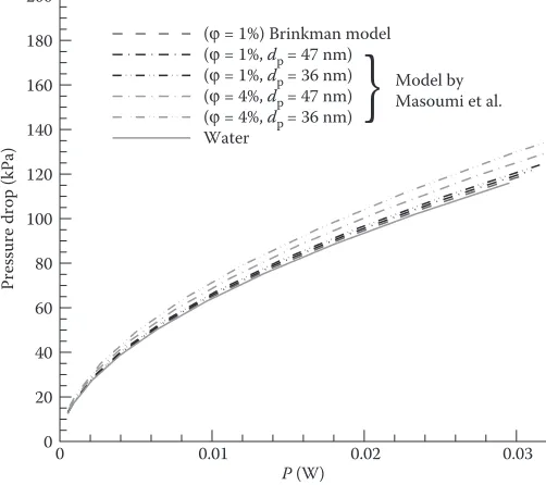
Figure 9.8). Fortunately, there is not much of a difference in pressure drops when using nanofluids with relatively small volume fractions, that is, about a 4% increase
Experimental data (Hwang et al. [27]) Present simulation
Shah’s equation [62,63]
q = 5000 W, D = 1.812 mm, ReD= 700 (a)
(b) 3000
2500
h
(W/m
2K)
2000
1500
4500 Experimental data (1% Al2O3–water nanofluid, Lai et al. [64]) Present simulation (1% Al2O3–water nanofluid)
Experimental data (water, Lai et al. [64]) Present simulation (water)
h
(W/m
2K)
4000
3500
3000
25000 0.1 0.2 0.3 0.4 0.5
z/L
0 500 1000
z/D
FIGURE 9.6 (a) and (b) F–K model validation by comparing the heat transfer coefficient in a mini-tube with existing experimental data and theoretical prediction.
P (W)
Pressure drop (kPa)
0 0.01 0.02 0.03
0 20 40 60 80 100 120 140 160 180 200
(φ = 1%) Brinkman model (φ = 1%, dp = 47 nm)
(φ = 4%, dp = 36 nm)
Water
(φ = 1%, dp = 36 nm) (φ = 4%, dp = 47 nm)
}
Model by Masoumi et al.
FIGURE 9.8 Pressure drop versus pumping power for nanofluid flow using two different viscosity models.
Re
Pressure gradient (kPa/m)
200 400 600 800 1000
0 500 1000 1500 2000 2500 3000 3500 4000 4500 5000 5500 6000 6500
(φ = 1%) Brinkman model (φ = 1%, dp = 47 nm)
(φ = 1%, dp = 36 nm) (φ = 4%, dp = 47 nm)
(φ = 4%, dp = 36 nm)
Water
}
Model by Masoumi et al.
FIGURE 9.7 Pressure gradient versus the Reynolds number for nanofluid flow using two different viscosity models.
for Al2O3–water with 1% volume fraction and 47 nm particles and approximately 7% for φ= 4% and dp= 36 nm, when employing the viscosity model by Masoumi et al. [52]. Thus, low-concentration nanofluids do not require much more additional pump-ing power for mixture flow in microchannels. Chein and Chuang [65] and Li and Kleinstreuer [66] provided very similar results based on experiments and numerical simulations, respectively.
9.3.4 convectIve heat transfer
In order to compare the thermal performance of nanofluid flow in the microchan-nel, the local heat-transfer coefficient as well as the thermal resistance for different pumping powers were compared for pure water flow and nanofluid flow with differ-ent volume fractions, employing the viscosity model by Masoumi et al. [52] and the
knf model by Kleinstreuer and Feng [57].
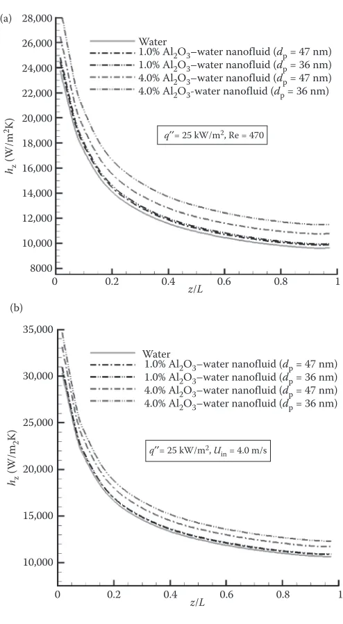
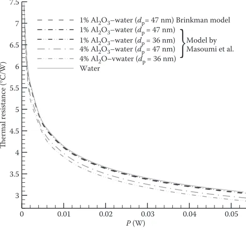
The local heat-transfer coefficient developing along the microchannel at the same inlet Reynolds number and heat flux for different fluids is shown in Figure 9.9a. As expected, the local heat transfer coefficient increases when using nanofluids, where smaller nanoparticles yield elevated heat transfer coefficients. It should be noted that the Reynolds number of nanofluids depends on the kinematic viscosity of the nanofluids, which increases with an increase in nanoparticle volume fraction and smaller nanoparticles, implying that the inlet velocity should be increased to keep the Reynolds number constant. Thus, to eliminate the dependence of hz on a varying Uin, Figure 9.9b depicts the heat-transfer enhancement for Uin = constant, demon-strating that the heat-transfer coefficient increases due to higher nanoparticle volume fractions and lower nanoparticle diameters. Interestingly, the thermal resistance (see Equation 9.28) decreases when employing nanofluids, especially for nanofluids with larger volume fractions and smaller nanoparticles (see Figure 9.10). The reason is that the average wall temperature is lower due to the higher thermal performance of nanofluids without a significant increase in pumping power. Overall, the average enhancement of thermal performance for Al2O3–water with a volume fraction of 4% is about 10% for 36 nm nanoparticles and 7% for 47 nm nanoparticles.
9.3.5 entropy GeneratIon
Focusing on the impact of inlet temperature and the Reynolds number, entropy gen-eration in trapezoidal microchannels is compared for flow of pure water and the 47-nm alumina–water nanofluid. As shown in Figure 9.11a, for a constant inlet veloc-ity total entropy generation decreases slightly with increasing inlet temperature. Assuming a constant inlet Reynolds number produces quite a different outcome, that is, Sgen(Tin) increases measurably (Figure 9.11b). For both cases nanofluids generate lower entropy rates than pure water. The thermal conductivity of the nanofluid is enhanced with an increase in bulk temperature (Tin), yielding lower temperature gra-dients (see Equation 9.20). As a result, total entropy generation is decreased with the increase of inlet temperature. In contrast, to maintain a constant inlet Reynolds num-ber, a lower inlet velocity is computed to balance the effects of viscosity and density changes resulting from the increasing inlet temperature. The lower bulk velocity
caused larger temperature gradients which in turn increased the total entropy gener-ation. Clearly, nanofluids generate less entropy than pure water (see Figures 9.11 and 9.12) because of the milder velocity and temperature gradients due to flatter velocity profiles and better heat transfer in the microchannel. The total entropy generation decreases with higher Reynolds numbers (Figure 9.12). This is quite beneficial when
(a)
(b) 28,000
Water
1.0% Al2O3–water nanofluid (dp = 47 nm)
1.0% Al2O3–water nanofluid (dp = 36 nm) 4.0% Al2O3–water nanofluid (dp = 47 nm) 4.0% Al2O3-water nanofluid (dp = 36 nm)
Water
1.0% Al2O3–water nanofluid (dp = 47 nm) 1.0% Al2O3–water nanofluid (dp = 36 nm) 4.0% Al2O3–water nanofluid (dp = 47 nm) 4.0% Al2O3–water nanofluid (dp = 36 nm)
q′′= 25 kW/m2, Re = 470
q′′= 25 kW/m2, U in = 4.0 m/s
26,000
24,000
22,000
20,000
18,000
16,000
14,000
12,000
10,000
8000
35,000
30,000
25,000
20,000
15,000
10,000
0 0.2 0.4 z/L 0.6 0.8 1
0 0.2 0.4 z/L 0.6
hz
(W/m
2K)
hz
(W/m
2
K)
0.8 1
FIGURE 9.9 Local heat-transfer coefficient developing along the microchannel using the new viscosity model by Masoumi et al. [52] and F–K thermal conductivity model: (a) at con-stant Reynolds number (b) at concon-stant inlet velocity.
dealing with high heat flux conditions, for example, heat sinks, where heat-trans-fer-induced entropy generation is dominant, especially at low Reynolds numbers. However, at higher Reynolds numbers the frictional part of entropy generation (see Equation 9.22) may be dominant. Hence, it may be desirable to operate a micro-system in a Reynolds number range associated with relatively low Sgen values. In addition to the Reynolds number, the channel geometry (i.e., aspect ratio) is also an important parameter for the minimization of a system’s total entropy generation, as pointed out by Li and Kleinstreuer [40].
9.4 CONCLUSION
Actual thermal conductivity enhancement of nanofluids knf over the “effective medium” theory of Maxwell is still subject to debate; although, most experimental-ists reported measurably elevated knf values. Associated theoretical models address-ing all the important physical phenomena explainaddress-ing possible knf enhancement are needed as well. After a brief review of the most recent papers concerning knf experi-mental observations and theoretical modeling, steady laminar thermal nanofluid flow and entropy generation in a trapezoidal microchannel were numerically analyzed. Specifically, two different viscosity models and thermal conductivity models for water flow and alumina–water nanofluid flow were compared after extensive com-puter model validations. The results show that nanofluids do measurably enhance the
P (W)
Thermal resistance (
°
C/W)
0 0.01 0.02 0.03 0.04 0.05
3 3.5 4 4.5 5 5.5 6 6.5 7 7.5
1% Al2O3–water (dp= 47 nm) Brinkman model
1% Al2O3–water (dp = 47 nm)
1% Al2O3–water (dp = 36 nm) Model by 4% Al2O3–water (dp = 47 nm) Masoumi et al.
4% Al2O–vwater (dp = 36 nm)
Water
}
FIGURE 9.10 Thermal resistance versus pumping power considering different viscosity models for different nanofluids.
thermal performance of microchannel mixture flow with a small increase in needed pumping power. Nanofluids with smaller nanoparticles at the same volume fraction exhibit a better convective heat-transfer performance, but they require more pump-ing power. The entropy-generation analysis indicates that Sgen reduces when using nanofluids due to their improved thermal transport mechanism.
Tin (K)
294 296 298 300 302 0.0016
0.0018 0.002 0.0022 0.0024 0.0026 0.0028
Water (Uin = 2.5 m/s)
1% Al2O3–water nanofluids (Uin = 2.5 m/s) 4% Al2O3–water nanofluids (Uin = 2.5 m/s)
(a)
Tin (K) ^ SG,to
ta
l
^ SG,to
ta
l
294 296 298 300 302 0.0016
0.0018 0.002 0.0022 0.0024 0.0026 0.0028 Water (Re = 470)
1% Al2O3–water nanofluid (Re = 470) 4% Al2O3–water nanofluid (Re = 470)
(b)
FIGURE 9.11 Entropy generation: (a) varying inlet temperature for the same inlet velocity and (b) varying inlet temperature for the same Reynolds number.
ACKNOWLEDGMENT
The use of ANSYS-CFX12.1 (Ansys, Inc., Canonsburg, PA) is gratefully acknowledged.
REFERENCES
1. J.C. Maxwell, A Treatise on Electricity and Magnetism, 3rd Edition, Clarendon Press, Oxford, UK, 1891.
2. R.L. Hamilton, O. K. Crosser, Thermal conductivity of heterogeneous two component systems, Industrial and Engineering Chemistry Fundamentals, 1, 187–191, 1962. 3. C. Kleinstreuer, Y. Feng, Experimental and theoretical studies of nanofluid thermal
con-ductivity enhancement: A review, Nanoscale Research Letters, 6, 229, 2011.
4. S. Ozerinc, S. Kakac, A. Guvenc, Y. Yazicioglu, Enhanced thermal conductivity of nano-fluids: A state-of-art review, Microfluidics and Nanofluidics, 8, 145–170, 2010. 5. S.M.S. Murshed, K.C. Leong, C. Yang, Thermophysical and electrokinetic properties of
nanofluids: A critical review, Applied Thermal Engineering, 28, 2109–2125, 2008. 6. E.V. Timofeeva, W. Yu, D.M. France, D. Singh, J.L. Routbort, Nanofluids for heat
trans-fer: An engineering approach, Nanoscale Research Letters, 6, 182, 2011.
7. J. Fan, L. Wang, Review of heat conduction in nanofluids, ASME Journal of Heat Transfer, 133, 040801–1–14, 2011.
8. S.K. Das, S. U.S. Choi, W. Yu, T. Pradeep, Nanofluids: Science and Technology, John Wiley & Sons, Inc., Publication, New Jersey, USA, 2008.
9. D. Li (Editor), Encyclopedia of Microfluidics and Nanofluidics, Springer, Amsterdam, Berlin, 2008.
Re
200 400 600 800 1000 1200 0
0.001 0.002 0.003 0.004 0.005 0.006 0.007 0.008 0.009 0.01 Water (Tin = 293 K)
1% Al2O3–water nanofluid (Tin = 293 K) 4% Al2O3–water nanofluid (Tin = 293 K)
^ SG,total
FIGURE 9.12 Entropy generation versus Reynolds number for different fluids.
10. C.S. Kumar (Editor), Microfluidic Devices in Nanotechnology: Applications, John Wiley & Sons, Inc., Publication, Hoboken, New Jersey, 2010.
11. B.C. Pak, Y.I. Cho, Hydrodynamic and heat transfer study of dispersed fluids with sub-micron metallic oxide particles, Experimental Heat Transfer, 11, 151, 1998.
12. Y. Xuan, W. Roetzel, Conceptions for heat transfer correlation of nanofluids, International Journal of Heat and Mass Transfer, 43, 3701–3707, 2000.
13. D. Wen, Y. Ding, Experimental investigation into convective heat transfer of nanoflu-ids at the entrance region under laminar flow conditions, International Journal of Heat Mass Transfer, 47, 5181–5188, 2004.
14. S.Z. Heris, M.N. Esfahany, G. Etemad, Investigation of CuO/water nanofluid laminar convective heat transfer through a circular tube, Journal of Enhanced Heat Transfer, 13, 279–289, 2006.
15. S.Z. Heris, M.N. Esfahany, S. Gh. Etemad, Experimental investigation of convective
heat transfer of Al2O3/water nanofluid in circular tube, International Journal of Heat
Fluid Flow, 28, 203–210, 2007.
16. J. Buongiorno, Convective transport in nanofluids, ASME Journal of Heat Transfer, 128, 240–250, 2006.
17. J.-Y. Jung, H.-S. Oh, H.-Y. Kwak, Forced convective heat transfer of nanofluids in microchannels, International Journal of Heat and Mass Transfer, 52, 466–472, 2009. 18. U. Rea, T. McKrell, L. Hu, J. Buongiorno, Laminar convective heat transfer and viscous
pressure loss of aluminar-water and zirconia-water nanofluids, International Journal of Heat and Mass Transfer, 52, 2042–2048, 2009.
19. P.S. Vajjha, D.K. Das, D.P. Kulkarni, Development of new correlations for convective heat transfer and friction factor in turbulent regime for nanofluids, International Journal of Heat and Mass Transfer, 53, 4607–4618, 2010.
20. R. H. Khiabani, Y. Joshi, C.K. Aidun, Heat transfer in microchannels with suspended solid particles: Lattice-Boltzmann based computations, ASME Journal of Heat Transfer, 132, 041003–1–9, 2010.
21. M. Hojjat, S.Gh. Etemad, R. Bagheri, J. Thibault, Convective heat transfer of non-Newtonian nanofluids through a uniformly heated circular tube, International Journal of Thermal Science, 50, 525–531, 2011.
22. J. Hemalatha, T. Prabhakaran, R. P. Nalini, A comparative study on particle-fluid inter-actions in micro and nanofluids of aluminium oxide, Microfluidics and Nanofluidics, 10, 263–270, 2011.
23. W. Escher, T. Brunschwiler, N. Shalkevick, A. Shalkevich, T. Burgi, B. Michel, D. Poulikakos, On the cooling of electronics with nanofluids, ASME Journal of Heat Transfer, 133, 051401–1–11, 2011.
24. P.E. Gharagozloo and K.E. Goodson, Temperature-dependent aggregation and diffusion in nanofluids, International Journal of Heat and Mass Transfer, 54, 797–806, 2011. 25. H. Xie, W. Yu, Y. Li, L. Chen, Discussion on the thermal conductivity enhancement of
nanofluids, Nanoscale Research Letters, 6, 124, 2011.
26. W.-H. Lee, C.-K. Rhee, J. Koo et al., Round-robin test on thermal conductivity measure-ment of ZnO nanofluids and comparison of experimeasure-mental results with theoretical bounds, Nanoscale Research Letters, 6, 258–282, 2011.
27. K.S. Hwang, S.P. Jang, S.U.S. Choi, Flow and convective heat transfer characteristics
of water based Al2O3 nanofluids in fully developed laminar flow regime, International
Journal of Heat and Mass Transfer, 52, 193–199, 2009.
28. X. Wu, H. Wu, P. Cheng, Pressure drop and heat transfer of Al2O3-H2O nanofluids
through silicon microchannels, Journal of Micromechanics and Microengineering, 19, 105020-1-11, 2009.
29. D. Kim, Y. Kwon, Y. Cho et al., Convective heat transfer characteristics of nanofluids under laminar and turbulent flow conditions, Current Applied Physics, 9, e119123, 2009.
30. H. Xie, Y. Li, W. Yu, Intriguingly high convective heat transfer enhancement of nano-fluid coolants in laminar flows, Physics Letters A, 374, 2566–2568, 2010.
31. M. Chandrasekar, S. Suresh, A.C. Bose, Experimental studies of heat transfer and
fric-tion factor characteristics of Al2O3/water nanofluid in a circular pipe under laminar flow
with wire coil inserts, Experimental Thermal and Fluid Science, 34, 122–130, 2010. 32. M. H. Fard, M. N. Esfahany, M.R. Talaie, Numerical study of convective heat transfer of
nanofluids in a circular tube two-phase model versus single-phase model, International Communications in Heat and Mass Transfer, 37, 91–97, 2009.
33. R. Lotfi, Y. Saboohi, A.M. Rashidi, Numerical study of forced convective heat transfer for nanofluids: Comparison of different approaches, International Communications in Heat and Mass Transfer, 37, 74–78, 2010.
34. M.M. Heyhat, F. Kowsary, Effect of particle migration on flow and convective heat transfer of nanofluids flowing through a circular pipe, ASME Journal of Heat Transfer, 132, 062401-1-9, 2010.
35. A. Akbarinia, M. Abdolzadeh, R. Laur, Critical investigation of heat transfer enhance-ment using nanofluids in microchannels with slip and non-slip flow regiomes, Applied Thermal Engineering, 31, 556–565, 2011.
36. S. Kondaraju, E.K. Jin, J.S. Lee, Effect of the multi-sized nanoparticle distribution on the thermal conductivity of nanofluids, Microfluidics and Nanofluidics, 10, 133–144, 2011. 37. J. H. Werth, M. Linsenuhler, S.M. Dammer, Z. Farkas, H. Hinichsen, K.E. Wirth, D.E.
Wolf, Agglomeration of charged nanopowders in suspensions, Powder Technology, 133, 106–112, 2011.
38. W. Jiang, G. Ding, H. Peng, H. Hu, Modeling of nanoparticles aggregation and sedimen-tation in nanofluid, Current Applied Physics, 10, 934–941, 2011.
39. W. Evans, R. Prasher, J. Fish, P. Meakin, P. Phelan, P. Keblinski, Effect of aggregation and interfacial thermal resistance on thermal conductivity of nanocompsites and colloi-dal nanofluids, International Journal of Heat and Mass Transfer, 51, 1431–1438, 2008. 40. J. Li, C. Kleinstreuer, Entropy generation analysis for nanofluid flow in microchannels,
ASME Journal of Heat Transfer, 132, 122401-1-8, 2010.
41. P.K. Singh, K.B. Anoop, T. Sundararajan, S.K. Das, Entropy generation due to flow and heat transfer in nanofluids, International Journal of Heat and Mass Transfer, 53, 4757–4767, 2010.
42. M. Kalteh, A. Abbassi, M. Saffar-Avval, J. Harting, Eulerian-Eulerian two-phase numer-ical simulation of nanofluid laminar forced convection in a microchannel, International Journal of Heat and Fluid Flow, 32, 107–116, 2011.
43. X. W. Wang, X. F. Xu, S. U. S. Choi, Thermal conductivity of nanoparticle-fluid mix-ture, Journal of Thermal Physics and Heat Transfer, 13, 474–480, 1999.
44. H. Chen, Y. Ding, C. Tan, Rheological behavior of nanofluids, New Journal of Physics, 9, 367–1–24, 2007.
45. C.T. Nguyen, F. Desgranges, N. Galanis et al., Viscosity data for Al2O3/water
nano-fluids-hysteresis: is heat transfer enhancement using nanofluids reliable, International Journal of Thermal Science, 47, 103–111, 2008.
46. S.M.S. Murshed, K.C., Leong, C. Yang, Investigations of thermal conductivity and vis-cosity of nanofluids, International Journal of Thermal Science, 47, 560–568, 2008. 47. A. Einstein, A new determination of the molecular dimensions, Annals of Physics, 19,
289–306, 1906.
48. H.C. Brinkman, The viscosity of concentrated suspensions and solutions, Journal of Chemistry Physics, 20, 571–581, 1952.
49. G.K. Batchelor, The effect of Brownian motion on the bulk stress in the suspension of spherical particles, Journal of Fluid Mechanics, 128, 240, 1977.
50. A.L., Graham, On the viscosity of suspensions of solid spheres, Applied Scientific Research 37, 275, 1981.
51. J. Koo, C. Kleinstreuer, Laminar nanofluid flow in microheat-sinks, International Journal of Heat and Mass Transfer, 48 (13), 2652–2661, 2005.
52. N. Masoumi, N. Sohrabi and A. Behzadmehr, A new model for calculating the effective viscosity of nanofluids, Journal of Physics D: Applied Physics, 42, 055501–1–6, 2009. 53. C. Kleinstreuer, Modern Fluid Dynamics, Springer, New York, NY, USA, 2010. 54. Y. Feng, C. Kleinstreuer, Nanofluid convective heat transfer in a parallel-disk system,
International Journal of Heat and Mass Transfer, 53, 4619–4628, 2010.
55. C.T. Nguyen, F. Desgranges, G. Roy et al., Temperature and particle size dependent vis-cosity data for water-based nanofluids-Hysteresis phenomenon, International Journal of Heat and Fluid Flow, 28, 1492–1506, 2007.
56. E. Abu-Nada, Effects of variable viscosity and thermal conductivity of Al2O3-water
nanofluid on heat transfer enhancement in natural convection, International Journal of Heat and Fluid Flow, 30, 679–690, 2009.
57. C. Kleinstreuer, Y. Feng, Thermal nanofluid property model with application to fluid flow in a parallel-disk system Part I: A new thermal conductivity model for nano-fluid flow, Journal of Heat Transfer, 134(5), 051002, 2012.
58. H. E. Patel, T. Sundararajan, S.K. Das, An experimental investigation into the thermal conductivity enhancement in oxide and metallic nanofluids, Journal of Nanoparticle Research, 12, 1015–1031, 2010.
59. Y. Feng, A New Thermal Conductivity Model for Nanofluids with Convection Heat Transfer Application, MS Thesis, NC State University, Raleigh, NC, USA, 2009. 60. H. A. Mintsa, G. Roy, C. T. Nguyen, D. Doucet, New temperature dependent thermal
conductivity data for water-based nanofluids, International Journal of Thermal Sciences, 48, 363–371, 2009.
61. R.K. Shah, Laminar flow friction and forced convection heat transfer in ducts of arbi-trary geometry, International Journal of Heat and Mass Transfer, 18, 849–862, 1975. 62. R.K. Shah, A.L. London, Laminar flow forced convection in ducts, Supplement 1 to
Advances in Heat Transfer, Academic Press, New York, 1978.
63. R.K. Shah, M.S. Bhatti, Laminar convective heat transfer in ducts, in: S. Kakac, R.K. Shah, W. Aung (Eds.), Handbook of Single-Phase Convective Heat Transfer, Wiley, New York, 1987 (Chapter 3).
64. W.Y. Lai, S. Vinod, P.E. Phelan, and R. Prasher, Convective heat transfer for water-based Alumina nanofluids in a single 1.02-mm tube, ASME Journal of Heat Transfer, 131, 112401, 2009.
65. R. Chein, J. Chuang, Analysis of microchannel heat sink performance using nanofluids, Applied Thermal Engineering, 25, 3104–3114, 2005.
66. J. Li, C. Kleinstreuer, Thermal performance of nanofluid flow in microchannels, International Journal of Heat and Fluid Flow, 29, 1221–1232, 2008.
67. I. Tavman, A. Turgut, M. Chirtoc, K. Hadjov, O. Fudym, S. Tavman, Experimental study on thermal conductivity and viscosity of water-based nanofluids, Heat Transfer Research, 41, 339–351, 2010.
68. S.K. Das, N. Putra, P. Thiesen, W. Roetzel, Temperature dependence of thermal conduc-tivity enhancement for nanofluids, Journal of Heat Transfer, 125, 567–574, 2003. 69. M. P. Beck, Y. Yuan, P. Warrier, A.S. Teja, The thermal conductivity of alumina
nano-fluids in water, ethylene glycol, and ethylene glycol + water mixture, Journal of
Nanoparticle Research, 12, 1469–1477, 2010.
70. C. H. Chon, K. D. Kihm, S. P. Lee, S. U. S. Choi, Empirical correlation finding the role
of temperature and particle size for nanofluid (Al2O3) thermal conductivity
enhance-ment, Applied Physics Letters, 87, 153107–1–3, 2005.