IJEDR1602089
International Journal of Engineering Development and Research (www.ijedr.org)490
1 Chhotubhai Gopalbhai Patel institute of Technology, Bardoli, Surat, India________________________________________________________________________________________________________
Abstract – Textile Industries were developed during the Historical Era in India. Surat is well-known for its textile industries and weaving technology. In older days Shuttle Looms machines were directly installed on a slab panel with same sort of foundation isolation. So the major cause which was established with the heap of this machine is VIBRATION. So as Frequency for a slab panel is being calculated by changing various parameters. The whole analysis procedure is being done using STAAD Pro. Software.
Index Terms – Textile Industry, Vibration, Frequency, STAAD Pro
________________________________________________________________________________________________________
I.INTRODUCTION
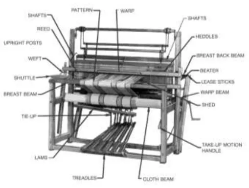
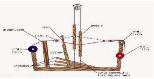
The Indian textile industry has a great legacy, which is perhaps unmatched in the history of India’s industrial development. India’s textile industry evolved and developed at a very early stage and its manufacturing technology was amongst the best. Prior to colonization, India’s manually operated textile machines were among the best in the world, and served as a model for production of the first textile machines in newly industrialized Britain and Germany. An apparatus which is hand operated or power driven for weaving fabrics, which contains harnesses, lay, reed, shuttles, treadle etc., is called Looms. The basic purpose of it is to wrap threads under the tension to facilitate the interweaving of the weft threads.
The modern looms machines have transformed the entire scenario of Textile production. It enables easy and faster production rate of textile manufacturing. These machines have proved to be a boon to Textile manufacturers in terms of economy and time. However, they come with an unseen drawback of “Vibrations” due to their high operating speed. The parameters normally used to assess the vibration are the amplitude and frequency. In order to completely define a vibration, the amplitude and frequency of motion are measured in three orthogonal directions, generally in terms of displacement which is considered to be the best description for assessing the potential damage response of a structure. These vibrations may cause varying degree of damage to the building components. Minor damage is seen in the building to non-structural components such as cracking of masonry walls, de-bonding of aggregate and cements gel, etc. However, if the amplitude of vibration increases, it may cause serious damage to structural components such as excessive deformation of beams, columns, fatigue failure and settlements; which may cause serious damage to life and property.
IJEDR1602089
International Journal of Engineering Development and Research (www.ijedr.org)491
Figure 2. Basic components of looms machineII.THEORYOFDYNAMICS
Dynamic Analysis:
Structural dynamics is a type of structural analysis which covers the Behaviour of structures subjected to dynamic (actions having high acceleration) loading. Dynamic loads include people, wind, waves, traffic, earthquakes, and blasts. Any structure can be subjected to dynamic loading. Dynamic analysis can be used to find dynamic displacements, time history, and modal analysis.
Parameters of Basic Structural Dynamics:
1. Amplitude
It is define as maximum displacement of a vibrating body from the mean position. 2. Frequency
Frequency may be defined as the number of complete cycles of oscillations which occur per unit of time. 3. Mode Shape
A mode shape is a specific pattern of vibration executed by a mechanical system at a specific frequency. Different mode shapes will be associated with different frequencies. The experimental technique of modal analysis discovers these mode shapes and the frequencies.
4. Vibration
A magnitude (displacement, force, or acceleration) which oscillates about some specified reference where the magnitude of the force, or acceleration is alternately smaller and greater than the reference. Vibration is commonly expressed in terms of frequency (cycles per second or Hz) and amplitude, which is the magnitude of the force, displacement, or acceleration.
If the motion of the body is oscillating or reciprocating in character, it is called vibration if it involves deformation of the body. In case the reciprocating involves only the rigid body movement without its deformation, then it is called oscillation.
E.g. Motion of a multi-storey building during earthquake is vibration as there is deformation of the building. There are mainly two types of vibration:
o Free Vibration
Free vibration occurs under the influence of forces inherent in the system itself, space without any external forces. However, to start free vibration, some external force or natural disturbance is required. o Forced Vibration
Forced vibration occurs under the influence of external existing force III.ANALYSISCRATERIA
The slab panel of a typical floor plan of an existing looms industrial building is to be considered as a problem on which the various properties are assigned and a machine by a beam element.
The Loads assigned to the given slab panel is listed below.
Dead Load; which includes Self-Weight, Masonry Load and Floor Finish load.
Live Load
Harmonic Load(Time History)
Dead Load + Live Load + Harmonic Load
IJEDR1602089
International Journal of Engineering Development and Research (www.ijedr.org)492
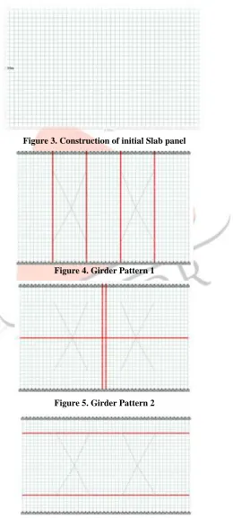
STTS Pro.Figure 3. Construction of initial Slab panel
Figure 4. Girder Pattern 1
Figure 5. Girder Pattern 2
IJEDR1602089
International Journal of Engineering Development and Research (www.ijedr.org)493
Figure 7. Analysis CommandV.RESULTS
Here the models are being developed for the various phase angles of the machine and by that for a one support condition i.e. for both end fixed support condition and a basic slab panels, frequency for various mode shapes in various phase angle conditions are being carried away in a table.
Table 1: Frequency of slab panel for fixed end support condition without any Girder for various phase angle condition
P-1 P-2 SUPPORT Frequency(CPS)
MODE 1 MODE 2 MODE 3 MODE 4 MODE 5 MODE 6
0 0 BOTH END FIXED 38.761 44.202 47.879 59.049 81.579 95.252
0 30 BOTH END FIXED 38.761 44.202 47.879 59.049 81.579 95.252
0 90 BOTH END FIXED 38.761 44.202 47.879 59.049 81.579 95.252
0 120 BOTH END FIXED 38.761 44.202 47.879 59.049 81.579 95.252
0 180 BOTH END FIXED 38.761 44.202 47.879 59.049 81.579 95.252
0 210 BOTH END FIXED 38.761 44.202 47.879 59.049 81.579 95.252
0 240 BOTH END FIXED 38.761 44.202 47.879 59.049 81.579 95.252
0 270 BOTH END FIXED 38.761 44.202 47.879 59.049 81.579 95.252
0 330 BOTH END FIXED 38.761 44.202 47.879 59.049 81.579 95.252
As shown in table 1, it seems that by making various changes in phase angle on machines frequency was not being changed for a same support condition and a same girder pattern with various cross beam section.
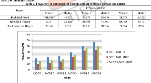
Part 1-Without any Girder
Table 2: Frequency of slab panel for various support condition without any Girder
Support Frequency(CPS)
Mode 1 Mode 2 Mode 3 Mode 4 Mode 5 Mode 6
Both End Fixed 38.761 44.202 47.879 59.049 81.579 95.252
Both End Hinged 20.61 22.216 28.065 44.565 65.468 68.121
One Fixed-One Hinged 29.207 32.52 36.838 50.786 74.564 79.271
Figure 8. Frequency Vs Mode Number for Part 1 0
20 40 60 80 100 120
MODE 1 MODE 2 MODE 3 MODE 4 MODE 5 MODE 6
Fr
eq
u
anc
y(CPS
)
Mode
BOTH END FIX
BOTH END HINGE
IJEDR1602089
International Journal of Engineering Development and Research (www.ijedr.org)494
Both End Hinged 22.96 23.183 31.972 47.204 69.536 77.117
One Fixed-One Hinged 33.114 33.759 40.147 54.122 77.149 92.782
Figure 9: Frequency Vs Mode Number for Part 2
From the above Table 3 and Fig 9 it seems that for both fixed end support; frequency increases to 147.44%, for both hinged end support; frequency increases to 235.875% and for one end fixed and one end hinged support condition; frequency increases to 180.189% from mode shape 1 to 6.
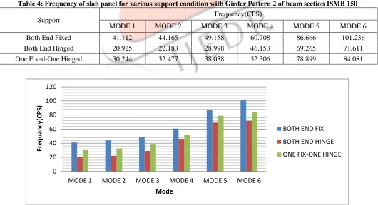
Part 3-With Girder Pattern 2 of beam section ISMB 150
Table 4: Frequency of slab panel for various support condition with Girder Pattern 2 of beam section ISMB 150
Support Frequency(CPS)
MODE 1 MODE 2 MODE 3 MODE 4 MODE 5 MODE 6
Both End Fixed 41.112 44.165 49.158 60.708 86.666 101.236
Both End Hinged 20.925 22.183 28.998 46.153 69.265 71.611
One Fixed-One Hinged 30.244 32.477 38.038 52.306 78.899 84.081
Figure 10. Frequency Vs Mode Number for Part 3 0
20 40 60 80 100 120
MODE 1 MODE 2 MODE 3 MODE 4 MODE 5 MODE 6
Fr
e
q
u
an
cy
(CPS)
Mode
BOTH END FIX
BOTH END HINGE
ONE FIX-ONE HINGE
0 20 40 60 80 100 120
MODE 1 MODE 2 MODE 3 MODE 4 MODE 5 MODE 6
Fr
e
q
u
an
cy
(CPS)
Mode
BOTH END FIX
BOTH END HINGE
IJEDR1602089
International Journal of Engineering Development and Research (www.ijedr.org)495
From the above Table 4 and Fig 10 it seems that for both fixed end support; frequency increases to 146.244%, for both hinged end support; frequency increases to 242.227% and for one end fixed and one end hinged support condition; frequency increases to 178.008% from mode shape 1 to 6.Part 4-With Girder Pattern 3 of beam section ISMB 150
Table 5: Frequency of slab panel for various support condition with Girder Pattern 3 of beam section ISMB 150
Support Frequency(CPS)
MODE 1 MODE 2 MODE 3 MODE 4 MODE 5 MODE 6
Both End Fix 40.012 44.625 48.074 59.5 82.056 97.257
Both End Hinge 21.457 22.527 28.705 44.979 66.85 68.586
One Fix-One Hinge 30.255 32.832 37.193 51.169 74.983 80.734
Figure 11. Frequency Vs Mode Number for Part 4
Fromthe above Table 5 and Fig 11 it seems that for both fixed end support; frequency increases to 143.069%, for both hinged end support; frequency increases to 219.643% and for one end fixed and one end hinged support condition; frequency increases to 166.845% from mode shape 1 to 6.
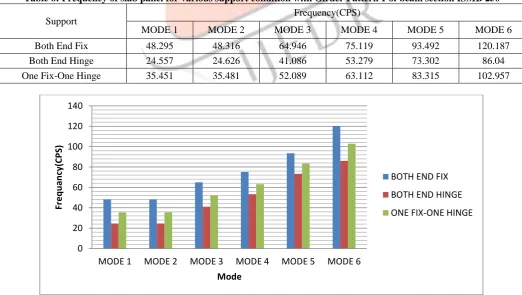
Part 5-With Girder Pattern 1 of beam section ISMB 250
Table 6: Frequency of slab panel for various support condition with Girder Pattern 1 of beam section ISMB 250
Support Frequency(CPS)
MODE 1 MODE 2 MODE 3 MODE 4 MODE 5 MODE 6
Both End Fix 48.295 48.316 64.946 75.119 93.492 120.187
Both End Hinge 24.557 24.626 41.086 53.279 73.302 86.04
One Fix-One Hinge 35.451 35.481 52.089 63.112 83.315 102.957
Figure 12: Frequency Vs Mode Number for Part 5 0 20 40 60 80 100 120
MODE 1 MODE 2 MODE 3 MODE 4 MODE 5 MODE 6
Fr e q u an cy (CPS) Mode
BOTH END FIX
BOTH END HINGE
ONE FIX-ONE HINGE
0 20 40 60 80 100 120 140
MODE 1 MODE 2 MODE 3 MODE 4 MODE 5 MODE 6
Fr e q u an cy (CPS) Mode
BOTH END FIX
BOTH END HINGE
IJEDR1602089
International Journal of Engineering Development and Research (www.ijedr.org)496
Both End Hinge 22.117 22.168 34.69 53.89 77.297 77.495
One Fix-One Hinge 32.518 32.549 45.629 59.539 91.629 91.866
Figure 13. Frequency Vs Mode Number for Part 6
Fromthe above Table 7 and Fig 13 it seems that for both fixed end support; frequency increases to 140.64%, for both hinged end support; frequency increases to 250.386% and for one end fixed and one end hinged support condition; frequency increases to 182.508% from mode shape 1 to 6.
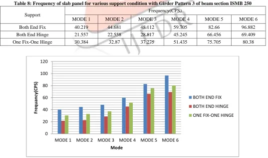
Part 7-With Girder Pattern 3 of beam section ISMB 250
Table 8: Frequency of slab panel for various support condition with Girder Pattern 3 of beam section ISMB 250
Support Frequency(CPS)
MODE 1 MODE 2 MODE 3 MODE 4 MODE 5 MODE 6
Both End Fix 40.219 44.681 48.112 59.705 82.66 96.882
Both End Hinge 21.557 22.558 28.817 45.245 66.456 69.409
One Fix-One Hinge 30.384 32.87 37.275 51.435 75.705 80.38
Figure 14: Frequency Vs Mode Number for Part 7 0
20 40 60 80 100 120
MODE 1 MODE 2 MODE 3 MODE 4 MODE 5 MODE 6
Fr
eq
u
anc
y(CPS
)
Mode
BOTH END FIX
BOTH END HINGE
ONE FIX-ONE HINGE
0 20 40 60 80 100 120
MODE 1 MODE 2 MODE 3 MODE 4 MODE 5 MODE 6
Fr
eq
u
anc
y(CPS
)
Mode
BOTH END FIX
BOTH END HINGE
IJEDR1602089
International Journal of Engineering Development and Research (www.ijedr.org)497
Fromthe above Table 8 and Fig 14 it seems that for both fixed end support; frequency increases to 140.886%, for both hinged end support; frequency increases to 221.978% and for one end fixed and one end hinged support condition; frequency increases to 164.547% from mode shape 1 to 6.VI.CONCLUSION
Frequency of a vibration does not depend on the various phase angle condition that is in any direction of movement of power looms machine frequency of that slab panel will not change for the particular mode shape.
Frequency of a vibration is purely depends on the Support Condition. For Both end Hinge Condition the Frequency is minimum and for Both End Fixed Condition the Frequency is maximum for the particular slab panel and mode shape i.e. stiffer the slab panel frequency will increases.
By adding the different girder pattern with different beam section the frequency of the slab panel would likely to increase for a particular pattern.
Frequency for mode shape 1 in no girder pattern condition is 38.761 CPS, for pattern 1 with beam section ISMB 150 is 44.97 CPS and for pattern 1 with beam section ISMB 250 is 48.295 CPS. It seems that by adding any girder beam section, the frequency of the structure will increase i.e. slab panel becomes stiffer by adding girders with various beam section.
A case of a slab panel when both ends are fixed and machine are running with same phase angle, in no girder condition frequency increases to 153.67%; in girder pattern 1 with beam section ISMB 150 condition frequency increases to 147.44% and in girder pattern 1 with beam section ISMB 250 condition frequency increases to 148.86% from mode 1 to 6. So it concludes that by adding girders the percentage in increment of frequency is decreased.
In this parametric study various stresses and moment values are being generated from plate stress contours using software STAAD Pro. To check the increment or decrement in the values of them for various cases taken in this study.
VII.ACKNOWLEDGMENT
My special thanks to Prof. K.N. Gandhi, Head of the Civil Engineering Department, CGPIT, Bardoli, Surat. For his Support and Guidance.
REFERENCES
[1] Gaurang A. Parmar, Yogesh D. Rathod, Sunil H. Kukadiya, Sarthi B. Bhavsar, Jigar K. Sevalia; Study On Remedial Measures To Control Machine Induced Vibration Of Factory Building; International Journal Of Engineering And Advanced Technology (Ijeat) Issn: 2249 – 8958, Volume-2, Issue-4, April 2013
[2] Jigar K. Sevalia, Ruchika S. Patel, Neel H. Shah, Akshay S. Agrawal And Neha Modi;Behavior Study Of Industrial Building Under Dynamic Load International Journal Of Current Engineering And Technology E-Issn 2277 – 4106, P-Issn 2347 - 5161 ,Volume-4, No-2, April 2014
[3] Jigar K. Sevalia, Sarthi B. Bhavsar, Sunil H. Kukadiya, Yogesh D. Rathod, Gaurang A. Parmar; Dynamic Analysis Of Structure For Looms Industry - A Parametric Study; International Journal Of Engineering Research And Applications (Ijera) Issn: 2248-9622 Www.Ijera.Com Vol. 2, Issue 6, November- December 2012, Pp.772-784
[4] M. Bharathi, Dr. Swami Saran And Dr. Shyamal Mukerjee; Analysis Of Reciprocating Machine Foundations Resting On Piles; Paper No. Co18; Iset Golden Jubilee Symposium, Indian Society Of Earthquake Technology ,Department Of Earthquake Engineering Building ,Iit Roorkee, Roorkee/October 20-21, 2012