IJEDR1401235
International Journal of Engineering Development and Research (www.ijedr.org)1318
Design and Development of intake pulse Resonance
chamber for four stroke engine
1
Vignesh Venkataraman,
2Ashish Madan,
3A.D. Dhale
1,2 Students , 3Associate Professor
Department of Mechanical Engineering, S.S.Jondhale College of Engineering, Dombivali(E),Thane-421 204,India 1[email protected], 2[email protected], 3[email protected]
________________________________________________________________________________________________________
Abstract -Most single cylinder engines do not return good fuel efficiency in traffic conditions due to start stop nature of the conditions .Owing to the lower torque of the engines , disengaging the clutch fully at lower engine speeds while starting from standstill may cause engine to stall , hence it becomes necessary to revise the engine higher than the required level to ensure that it does not stall. This causes extra fuel to be burned and increases the running cost of the vehicle. The main objective is to reduce the fuel consumption of a small displacement engine by increasing the torque at low engine speeds by achieving a ram air effect. Intake pulse resonance chamber uses the concept of Helmholz resonance to achieve a ram effect in the intake manifold.This effect is used to effectively negate the effect of valve overlap which causes a return of air fuel charge into the manifold at lower operating speeds thereby achieving a higher efficiency at the lower engine speeds.
________________________________________________________________________________________________________ 1. INTRODUCTION
The small displacement engines found on most modern Indian two wheelers suffer from low torque at low RPM’s . The fuel consumption of a four stroke small-displacement commuter motor cycle engine is the least in its midrange due to the availability of the torque in that range of RPM’s. Most single cylinder engines do not return good fuel efficiency in traffic conditions due to start stop nature of the conditions .Owing to the lower torque of the engines , disengaging the clutch fully at lower engine speeds while starting from standstill may cause engine to stall , hence it becomes necessary to re-vise the engine higher than the required level to ensure that it does not stall. This causes extra fuel to be burned and increases the running cost of the vehicle.
The main objective of the is to reduce the fuel consumption of a small displacement engine by increasing the torque at low engine speeds by achieving a ram air effect. To achieve the objective we have to design a chamber to use the negative pressure pulses generated during the intake stroke and achieve a ram air effect for intake air fuel mixture . The global trend of downsizing engines to meet the stricter emission norms means that smaller engines suffer from lower torque compared to older engines which had higher displacement. Like the expansion chambers of the two stroke engines which use the principle of resonance, we can design a resonance chamber to overcome the problem of the small displace-ment four stroke engine . By using a resonance chamber we can only eliminate the problem of low torque but also avoid the need to alter the design of the engine. The engines are mostly geared to achieve a cruising speed of around 40-60 kph in the mid- range so that the maximum cruising efficiency is achieved. This means that the engines are mostly run the lower end of the RPM range in start stop traffic conditions. This selection of the gearing ratios requires knowledge related to automo-bile, mechanical and production. However we can use the concept of resonance to achieve an increase in the efficiency of the engine .The main advantage of not redesigning any functional component is not only saving in costs but also the option of fitting the chamber as an aftermarket add-on to existing vehicles.The vehicle selected for the development to be implemented on is the TVS Apache RTR 180. The primary reason for the selection of the said vehicle is that the engine is robust can take additional stresses of operating with higher state of tune. It is also easy to find replacement parts and details about the engine due to easy availability.
When the intake stroke of the four stroke engine begins the intake poppet valve opens and causes a negative pressure pulse to travels up the intake manifold and the energy dissipated in the air-box.The intake pulse is to be harnessed by providing a reso-nance chamber up to the intake manifold.The return pulse is timed to just reach the intake port just before the piston reaches the bottom dead centre by using a calculated effective length for the pulse to travel through the resonance chamber.This causes the part of air-fuel charge which normally returns up the intake port during low RPM operation remain in the combustion chamber and also a little extra air fuel charge to enter the combustion chamber every cycle and hence leads to a higher effective
compres-sion ratio thereby increasing the volumetric efficiency of the engine during the low RPM operation. The target RPM for the chamber to provide boost due is selected at 2000 rpm. The chamber is to be accordingly designed for
IJEDR1401235
International Journal of Engineering Development and Research (www.ijedr.org)1319
Vehicle selected TVS apache RTR 180
Engine displacement 177.3 cc
Bore 62.5 mm
Stroke 57.8 mm
Inlet valve diameter 28.0 mm Inlet port diameter(at valve seat) 27.5 mm Exhaust valve diameter 25.0 mm Exhaust port diameter(at valve seat) 24.5 mm
Inlet valve opens 6 degrees before T.D.C
Inlet valve closes 41 degrees after B.D.C
Exhaust valve opens 42 degrees before
B.D.C
Exhaust valve closes 4 degrees after T.D.C Table1.1- Technical Details of selected Vehicle’s Engine
Fig 1.1- Valve timing Diagram of selected Vehicle
2.MATERIALS AND METHODOLOGY
The target vehicle was ridden in start stop traffic to estimate the optimum engine speed to design the chamber to provide the boost. It was then noted that the maximum benefit would be achieved if the boost is provided for the engine between 1500 & 2500 rpm. Thus we consider the target value at the exact middle of the required rpm range for the calculations.We hence have 2000 rpm as the target engine speed The four stroke engine requires two complete rotations of the crank for one cycle i.e. 720 degrees .Therefore,time for one complete cycle ( in seconds @ 2000 rpm) is 0.06 seconds.From the earlier data, total angle of crank rotations for which intake valve remains open is 227 degrees hence, the total time for which the intake valve remains open (Tr ) is 0.0189 seconds. The pressure pulse begins when the intake valve opens. We need to have the reflected pressure wave pulse reach the ports end . When the piston is at BDC so that the air-fuel in the cylinder is not pushed back when the piston begins to move up again.Thus, the pulse wave needs to return to the intake valve after 186 degrees of crank rotation.The total wave travelling time is 0.0155 seconds. Hence, the frequency of the operation for calculating the length of travel is calculated to be 20.83 Hz. Now, for a tuned length Helmholtz chamber,
F2 ={1/(2 x 3.14157)} x {{((N +(L1/L2)+1) +((N+(L1/L2)+1)2)-4}0.5 (2 x L x 0.00000173)]
Where,
N = Number of cylinders ; L1, L2 =Length of individual cylinder tracts L = Desired Length of chamber ; L1/L2 = 1 { for single cylinder engine}
IJEDR1401235
International Journal of Engineering Development and Research (www.ijedr.org)1320
Thus ,L = 86 cmLength of chamber = (L / 2) = (86 / 2) = 43 cm
Discharge, Q = Area x Velocity
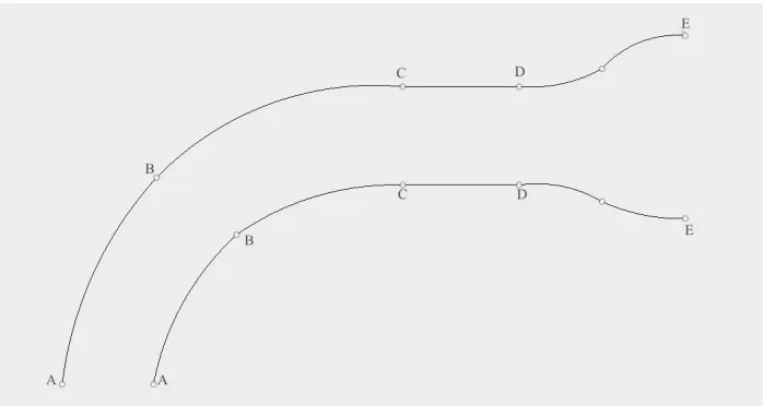
In the figure below Section A-A has a diameter of 27.5 mm.The diameter increases gradually unto Section B-B where it becomes 29.2 mm.It then remains constant till section D-D after which it increases to 50.20 mm at E-E.The point C-C is the part where the carburettor is attached to the engine head and the runner from section A-A to C-C is part of the engine head while from C-C to E-E is a part of the carburettor.
Fig.2.1- Cross-Section of Intake runner
Let us consider the sections at place where there is a change in diameter of the manifold, from figure2.1 Through the sections,(A-A) to (B-B),
A1 x V1 = A2 x V2 ; D12 x V1 = D22 x V2 ;(27.5 x 27.5) x V(1) = (29.36 x 29.36) x V(2) V1 = 1.139 V2 ; LE1 = L1 / (1.139)
By substituting L1 , we get : LE1 = 55.83 mm .
Now , considering the section diameter from (B-B) to (D-D)
LE2 = [{L2 + L3} / 1.139] = [{20.68 + 43.80} / 1.139] = 56.62 mm Now , considering the section diameter from (D-D) to (E-E) 29.362 V2 = 50.202V3
V2 = 2.923 V3,
Thus we have to calculate the effective length of the flow track from section(A-A) to section(E-E) and then subtract it from the calculated length of the chamber of 43 cm .
Thus, LE3 = L4/ (3.32) = (49)/(3.32) = 13.04 mm Thus , the total length of the carburettor mouth is :
LE = LE1 + LE2 + LE = (1.304)+(5.661)+(5.583) = 12.548 cm Now,
Length of the chamber = (43) - (LE = (43) - (12.543) = 30.456 cm But the length is the length of a chamber with a diameter of 21.5 mm
In practice, using a 27.5 mm diameter pipe, before the carburettor mouth will cause a large restriction to the flow of air Thus, the calculated effective length of the chamber with the 50.20 mm inner diameter which is :
LEC = (LENGTH OF THE CHAMBER)/(3.32)= 9.17 cm 3.Results and Discussion
The trials were conducted for the chamber which was designed.Here, the fuel consumption was measured by a calibrated bottle connected to the carburettor . We obtained the following results :
Engine running at 2000rpm Fuel consumed Distance covered(Running vehicle)
Time taken for fuel con-sumption(Idling)
Without chamber attached 10 ml 400 m 68 s
With the chamber attached 10 ml 450 m 69 s
Table 3.1- Engine performance with chamber v/s without chamber
IJEDR1401235
International Journal of Engineering Development and Research (www.ijedr.org)1321
Figure 3.1- Side view of Resonance chamberFigure 3.2 - Graph of torque v/s rpm from chassis dynamometer test
In figure 3.2 the test 1 shows the characteristics without the chamber attached while the test 2 shows characteristics of the engine with the chamber attached.The peak torque is lower when the chamber is attached due to the restrictions caused to the flow by the presence of the reed valve.The result of the dynamometer test carried out on the vehicle shows a significant increase of the en-gine’s torque at the target speed but it causes a restriction in the performance at speeds above 6500 rpm.Although it is a problem for high revving engines like those found in high performance motorcycles and race cars,it is not a relevant problem for regular commuter vehicles and cars whose engines do not rev beyond 6500 rpm. Multiple tests were carried out on the dynamometer and the average results were taken into account while plotting the graphs.The use of the vehicle in traffic conditions without the chamber attached gave a consistent mileage of about 40 Kilometres per litre while the same with the chamber attached consistent-ly gave close to 45 Kilometres per litre.The tendency of the engine to stall when the vehicle started from standstill was also great-ly reduced when the chamber was attached in spite of little or no opening of the throttle by the rider.
4.REFERENCES
[1] Gosman A.D., Tsui Y.Y., and Watkins A.P. (1984). “Calculation of Three Dimensional Air Motion Model Engines.” SAE Paper 840229.
[2] Kondoh T., Fukumoto A., Ohsawa K., and Ohkubo Y. (1986). “An assessment of a multi-dimensional numerical method to predict the flow in internal combustion engines.” SAE Paper 850500.
[3] Wakisaka T., Shimamoto Y., and Issihiki Y. (1986). “Three- dimensional numerical analysis of in-cylinder flows in recip-rocating engines.” SAE Paper 860464.
IJEDR1401235
International Journal of Engineering Development and Research (www.ijedr.org)1322
[5] Theodorakakos A., and Bergeles G. (1993). “Predictions of the in-cylinder fluid motion of a motored internal combustionengine.” Entropie No. 174/175.
[6] Capetti A. “Effect of intake pipe length on the volumetric efficiency of aninternal combustion engine”, NACA TM 501, 1929 (taken from Ann. R. Scuola d’Ingegneria di Padova, University of Padova; December 1927).
[7] Benson RS. “The thermodynamics and gas dynamics of internal combustion engines”. In: Horlock JH, Winterbone DE, editors, vol. 1. Oxford: Clarendon Press; 1982.
[8] Ohata A, Ishida Y. “Dynamic inlet pressure and volumetric efficiency of four cycle four cylinder engine”, SAE paper 820407; 1982.
[9] Winterbone DE, Pearson RJ. “Design techniques for engine manifolds: wave action methods for IC engines”. London: Professional Engineering Publishing Ltd.; 1999.