Wenguo Liu and Alan F.T. Winfield
AbstractThis paper describes the distributed self-assembly of a multi-robot ‘or-ganism’ from a swarm of autonomous heterogeneous modular mobile robots. A distributed self-assembly strategy based on a symbol sequence representation is pro-posed. Constructed from a tree representation of an organism, the symbol sequence is presented as a well organised nested structure in a compact format. It includes not only information on the topology of the organism but also how the organism will be self-assembled. The proposed approach has been tested with real robot pro-totypes. Results show that robots can successfully self-assemble to required target body plans within certain time frames.
1 Introduction
Self-reconfigurable modular robots has became a popular research topic since late 1980’s. From the CEBOT [1] to the SYMBRION project [2], more than 30 systems have been developed over 2 decades. Although earlier studies focused mainly on solving the mechanical engineering challenges for designing the hardware, recent research has paid more attention to high level algorithms toward greater controlla-bility of self-assembly, self-reconfigurable and self-repair of the system. The com-plexity of the modules and the architecture of the system vary in different studies. Some use a lattice architecture where docking/undocking can only occur at points within some virtual cells. The lattice architecture requires a simpler mechanical de-sign and simplifies the computational representation, thus the reconfiguration plan-ning is more achievable and scalable. Some other systems do not use the virtual cell as the docking point for their units. Instead, a number of modules can form a chain to reach any point in the operating space; the so called chain architecture. To
Wenguo Liu and Alan F. T. Winfield
Bristol Robotics Laboratory, University of the West of England, Bristol, UK. e-mail: [email protected], [email protected]
get to a specific point and carry out reconfiguration, the chain architecture requires a more complicated design with additional sensing. To overcome the limitation of both approaches, a hybrid architecture is favoured by many recent designs. Among these, a singular design of individual module is normally used, i.e. a homogeneous design. Apart from the essential functionality requirement of the modules, e.g. me-chanical docking, some degree of freedom of rotation, robots have been provided with a very limited range of sensors as appropriate to the design challenge and research interests. Also, few designs have considered providing individual robots with autonomous motion capabilities. This typically requires that modules have to be manually attached to each other prior to any reconfiguration process. The lack of sensing and mobility limits the possibility of re-assembling after pre-assembled structures have fallen apart either purposely or accidentally.
To close the gap between the modular robotic systems and multiple/swarm robotic systems, more recently researchers are seeking new designs that are capa-ble of autonomous self-assembly and self-reconfiguration. The SamBot [3] project consists of a group of identical robots. Each robot is equipped with two differential driven wheels and several IR sensors for autonomous self-assembly. As with many other modular robotic systems, a rotation arm is used in SamBot to provide one extra degree of rotation freedom thus enabling the self-reconfiguration capability. In contrast, the SYMBRION project (www.symbrion.eu) takes a heterogeneous ap-proach, and robots with more sensing, computation and actuation. Various modules with complementary motion capabilities have been developed for this project. The main focus of SYMBRION is to investigate the controllability and evolvability of artificial multi-cellular organisms from both engineering and scientific perspectives. The SYMBRION robots can either work fully autonomously with their own sens-ing and locomotion capabilities to explore the environment, or physically dock with each other forming different organism structures to accomplish more complex tasks that a single robot is not capable of, for example, climbing a wall or moving over a gap.
configuration to 3D configuration and, with respect to locomotion, will function as a macroscopic whole. The aggregated organism will also be able to disassemble and reassemble into different morphologies to fit the requirements of the task.
In our previous work, an ID-based strategy was proposed to self-assemble the SYMBRION robots into certain predefined 2D structures [9]. The ID-based ap-proach assumed that all robots in the swarm are identical and each robot stores the same set of predefined structures information. In addition, this strategy allows only one robot to join the organism at a time, using a fixed docking face, more specif-ically, the Front side, which constraints the toplogy of the shapes the swarm can self-assemble to. This paper will extend the previous work by removing all these assumptions and limitations. A new strategy will be developed to enable the parallel recruiting and any-side-docking in order to improve the efficiency and robustness of the self-assembly strategy. In particular, the new propsed strategy will take the heterogeneity of the system into account.
The rest of the paper is organised as follows: Section 2 introduces the robots of the SYMBRION project and the hardware configuration for autonomous docking. Section 3 proposes the internal representation of organism body plan for the self-assembly process. Section 4 outlines the controller framework and discusses the morphology control strategy. The proposed approach is validated in Section 5 using simulation and real robot experiments. The paper ends by drawing some conclusions and further work in Section 6.
2 The Robots
Figure 1 shows three types of robots developed in the project. These robots have different shapes and are equipped with different locomotion actuators. The Back-bone robot has two specially designed wheels which allow the robot to move for-wards, backwards and sideways; this robot requires a flat surface. With its tracked locomotion the Scout robot can move across uneven surfaces and is suitable for ex-ploration tasks. Like many other modular robots, both Backbone and Scout robots have cubical shapes with four docking faces and one degree of freedom of bending. The ActiveWheel robot is designed to carry and transport an organism consisting of several Scout or Backbone robots in the most energy-efficient way. It consists of two symmetrically arranged arms, connected via a 180◦turning hinge, and 4 omni-wheels. Two docking elements are placed on the same axis of the hinge for docking with other robots.
(a) BackBone robot (b) Scout Robot
[image:4.595.164.439.78.332.2](c) ActiveWheel Robot
Fig. 1: Robot prototypes. The BackBone robot has 4 active docking faces. The Scout robot has 2 active docking faces and 2 passive docking faces, while the ActiveWheel has only 2 passive docking faces.
..
.
A
.
B
.
B
.
B
.
A
.
C
.
C
.
D
.
E
.
F
(a) Active docking unit
..
.
A
.
A
.
B
.
B
.
B
.
C
.
C
.
D
.
E
(b) Passive docking unit
[image:4.595.157.452.391.515.2]electrical features. Note that for any valid robot-robot connection, at least one active docking unit needs to be present so that two docking units can be locked securely.
Infrared(IR)-based sensing - including proximity detection, docking alignment detection and local communications circuits - has been developed for the SYM-BRION robot to achieve autonomous docking in a 2D planar environment [10]. These sensors have similar placement on each docking face of the robot. More specifically, two IR sensors have been placed symmetrically above and on either side of the docking unit; one IR LED is placed directly above the docking unit, while the other two LEDS are located on either side of the docking unit. These LEDs are used to emit different frequency signals for obstacle detection, docking alignment and communication. The IR sensors work for both obstacle detection and docking alignment detection. IR remote control receivers are placed next to the IR LED on each docking face for communications.
3 Internal representation of organism body plan
To investigate how specified organism shapes can be self-assembled from a swarm of freely mobile robots, a common representation of the target shape must first be de-fined. The representation is also essential for the topology exploration of the organ-ism in the macro-locomotion and the self-reconfiguration tasks. This study assumes that the self-assembly process always occurs in a 2D planar environment between a partially formed organism and a group of freely moving robots where individual robots join the growing organism using their own locomotion. The hardware con-straints of the robot platform indicate that at any time one robot can attach to the partially formed organism using only one docking port. Thus no circular paths can appear among several connected modules in the target organism shapes. The body plan of an organism in a 2D planar environment can therefore be represented as a tree structureT. If letT = (V,C), thenV is a set of nodes andCrepresents a set of connections. Each nodev∈ {r1,r2, ...,rm}corresponds to a robot module in the
organism, whereri is the type of robots andmis the total number of types in the system. Each connectionc= ((v1,o1),(v2,o2))includes a pair of nodes(v1,v2)and
the orientation of corresponding connection ports,o1ando2. Note that each type of
robotrican havekiconnection ports. Clearly, unlike the common representation of a tree, there is no root node in the organism body plan and each node may have a different type.
withnrobots, a symbol sequenceSof tree T is defined as a sequence of 2(n−1)
symbolssgenerated from a depth first traversal ofT. There are two kinds of sym-bols in a sequence, sc andsp, wheresc= f(c)is a “connection” symbol, which corresponds to a connectionc= ((v1,o1),(v2,o2))inT using a mapping function
f(), whilespis a special “pairing” symbol. The size of “connection” symbol|sc| equals(∑ki)2and “pairing” symbol|sp|is 1.
S K A K S K S S
(a) Organism body plan
S
S K S
K A K S F R L F
R F B L
B F R F B F
(b) Tree represention
S
S K S
K A K S 1 2 3 4 5 6 7 8 9 10 11 12 13 14 seed
[image:6.595.137.464.195.379.2](c) Order of traversal
Fig. 3: An example of organism body plan and its tree representation. ‘K’ represents BackBone robot, ‘A’ for ActiveWheel robot and ‘S’ for Scout robot. ‘F’, ‘R’, ‘B’, ‘L’ denotes the Front, Right, Back and Left docking ports of a robot respectively.
KFKL KF SR 0 0 0 0 KRS F 0 0 0 0 KBS L 0 0 0 0 0 0 0 0 KBAF ARKF KBS F 0 0 0 0 0 0 0 0 0 0 0 0
1 2 3 4 5 6 7 8 9 10 11 12 13 14
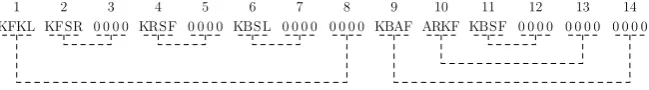
Fig. 4: An example symbol sequence of the organism. Each pair ofscandsp sym-bols, annotated and connected with dashed lines, represent one edge in its tree rep-resentation.
[image:6.595.137.462.462.507.2]body plan shown in Fig.3(a) as an example. There are 3 Backbone, 4 Scout and 1 ActiveWheel robots in the organism where the headings are indicated with triangles and the rotation axes are marked with a bar. Its corresponding tree representation is shown in Fig.3(b) and all connected docking ports are labelled along the edges. Starting from a node marked with dark colour, Fig.3(c) depicts the order of each edge being visited in a depth first traversal, which follows the travel order of “Front → Right→ Back→ Left” for each node. Through the traversal, asc symbol is added to a symbol sequence if an edge is first traversed and aspsymbol is added each time an edge is traversed in the opposite direction. For simplification, letscto be a string in a format of “parent node type|parent connection side|child node type |child connection side”, where each node type or connection side is denoted with one character, andspto be a string of “0000”, then the generated symbol sequence can be presented as shown in Fig. 4. Here the node types are abbreviated as ‘K’, ‘S’ and ‘A’ for Backbone, Scout and Activewheel robot respectively, while connection sides ‘F’, ‘R’, ‘B’ and ‘L’ stand for Front, Right, Back and Left respectively. For instance, a symbol of “KFKL” can be read as a traversal along the edge from a Backbone robot’s front side to another Backbone robot’s left side. Also shown in 4, the symbol sequence can be annotated as a nested structure. For eachscsymbol, there is a corresponding pairing symbolspin the sequence. Each pair ofscandsp symbols corresponds one edge in the tree representation. Their relative positions then depict the topology of the tree structure.
A symbol sequence can be obtained recursively from a depth first traversal of the tree. By carefully choosing the mapping function f(c)and pairing symbolsp, the generated symbol sequence requires only a small amount of memory to be stored and transferred. For example, in this study eachscsymbol is constructed using only 1 byte, with every two bits storing the robot type or the orientation of the connected docking port as shown below. If let 1 - 3 denote the robot type ‘K’, ‘S’ and ‘A’
7 6 5 4 3 2 1 0
parent node type
parent node docking port
child node type
child node docking port
respectively and 0 - 3 correspond to the connection ports ‘F’, ‘R’, ‘B’ and ‘L’ re-spectively, then a symbol of “KFKL” can be depicted as 0b01000111 = 0x47, while symbolspcan be identified using 0.
body plan can not be self-assembled because of the physical interference between robots.
Algorithm 1symbol sequence to graph representation
Precedure: OgSequenceTraversal (symbol sequenceS, treeT, nodev) 1: foreach branch sequenceSbinSdo
2: create new nodewfromSb.symbols[0];
3: insertwtoT
4: ifvis not empty nodethen
5: connectwwithv;
6: end if
7: create a new symbol sequenceS1by removing the first and last symbol ofSb;
8: OgSequenceTravelsal(S1,T,w); 9: end for
4 Self-assembly strategy
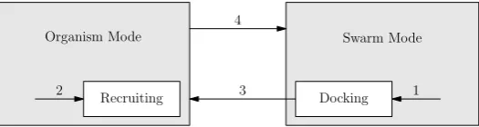
In SYMBRION scenarios, depending on whether physically connected to other robots, a robot works in one of two modes: swarm mode and organism mode, and switches between them accordingly. The transition from swarm mode to organism mode is determined by the morphology control strategy. In general, successful dock-ing requires the collaboration between two robots: one remains stationary, called the recruiter, which emits some guiding signals; the other moves and aligns along these signals and then docks to the recruiter. To build an organism shape, the process needs to be initialised by a robot, called the seed. During the self-assembly process, one freely moving robot can dock and join to the partially formed organism only when it is signalled. To grow the correct body shape, it is critical that the right robots in the organism mode become recruiters at the right time, and the right type of freely moving robots respond to the recruiters.
Docking
Recruiting 1
2 3
4
[image:8.595.170.433.500.570.2]Organism Mode Swarm Mode
This paper adopts a finite state machine as the controller framework for all robots. Figure 5 shows part of the controller which focuses on the topic of this paper, a com-plete version can be found in [9]. Once the self-assembly process starts, the seed robot becomes the first recruiter in the organism and thus moves to state Recruit-ing. Assuming that the target organism shape has been already stored as the symbol sequence in its memory, the seed robot extracts the branch symbol sequences from the complete symbol sequence. A branch symbol sequenceSbofS is defined as a sub symbol sequences between one of the starting nodevoassociatedscsymbol and corresponding pairedsp symbol. The number of branch symbol sequences equals the number of associatedscsymbols ofS. For example, the symbol sequence shown in Fig.4 has two branch symbol sequences: “KFKL KFSR 0000 KRSF 0000 KBSL 0000 0000” and “KBAF ARKF KBSF 0000 0000 0000”. Each branch sequence is in fact endowed with connection information to its descendants in the target organ-ism body shape. The seed robot can therefore use this information to decide which types of robot need to be recruited from which docking port. The behaviours in the Recruitingstate can be grouped into different stages:
stage 1 broadcast recruiting message from corresponding docking ports, indicat-ing the types and connection side of the robot recruited;
stage 2 emit guiding signals to help docking robots to align to them;
stage 3 synchronise the locking process if required, as both active docking unit and passive docking unit may be involved;
stage 4 send the branch symbol sequences to newly docked robots.
Any robots in swarm mode may become docking robots when recruiting mes-sages are received and their type matches with that requested. The docking robot then moves close to the recruiter guided by the signals and docks to it using the correct docking port. Upon receiving the branch symbol sequenceSbfrom the re-cruiter, it extracts a new symbol sequenceS1by removing the firstscsymbol and the lastspsymbol inSb. This new symbol sequence represents the sub tree which is rooted from itself. If there are branch sequences in the symbol sequenceS1, the
newly joined robot becomes a recruiter and moves into stateRecruitingto recruit more robots into the organism. Otherwise it changes state to organism mode and hence stops any further growth of the organism from itself. A recruiter exits the Recruitingstate once all its required docking ports are joined by other robots. Al-gorithm 2 outlines the behaviours for the recruiter and docking robots. Note that the exact behaviours in each state can have different implementations because of the heterogeneity of robots.
Algorithm 2Self-assembly strategy for recruiter and docking robots
Behaviour: in stateDocking
1: ifdocking is NOT accomplishedthen
2: locate and align to the recruiter;
3: else ifnew symbol sequence information receivedthen
4: extract the branches from received symbol sequence; 5: ifbranches exisitthen
6: enable the corresponding docking ports; 7: start to emit beacon signals;
8: move to stateRecruitment; 9: else
10: issue a message token to check progress of self-assembly; 11: ifmessage token is returnedthen
12: ifNo recruiters are presentedthen
13: notify the completion of self-assembly;
14: end if
15: move to organism mode;
16: end if
17: end if
18: end if
Behaviour: in stateRecruitment
19: ifAll required docking port is dockedthen
20: move to organism mode; 21: else
22: forEach recruiting docking portdo
23: ifnew robot is dockedthen
24: send branch symbol sequence; 25: stop emitting guiding signals;
26: else ifcurrenttime % RECRUITMENT SIGNAL INTERVALthen
27: broadcast recruiting message;
28: end if
29: end for
30: end if
token travels across the organism following some rules, for example in the same way a symbol sequence is generated, and back to the original sender. Once it shows no recruiters are present in the organism, the self-assembly process is assumed finished and the sender will issue another message to notify the success of morphogenesis to all robots. The selection of such a sender remains open. It can be any robot in the organism. A good candidate is however the most recently joined robot that has no other robots to be recruited, i.e. a leaf node robot in the tree representation. In other words, whenever a leaf node robot joins the organism, a progress check of self-assembly will be performed.
been acknowledged. A full analysis of effect of communication failures on the al-gorithm is presented in [11].
5 Experiments and discussion
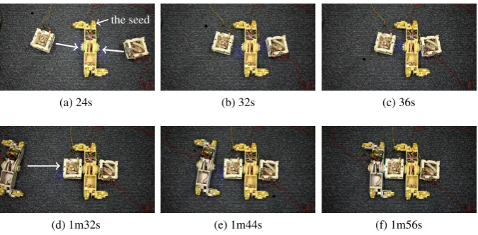
The proposed controller and self-assembly strategy has been implemented and tested with a small number of real prototype SYMBRION robots. Each robot runs the same controller framework as described in the paper and utilises the IR signals for recruiting and docking alignment. Autonomous docking between the recruiter and a docking robot is synchronised via local sensing and wireless communication. The locomotion control for each type of robots has been carefully designed accord-ing to their unique hardware specification. As the initialisation of the self-assembly process is out the scope of this study, each time a seed robot is chosen manually with a predefined symbol sequence to start the self-assembly process. Fig. 6 shows the progress of autonomous self-assembly of an organism with 2 ActiveWheel and 2 BackBone robots. The approach was successfully and repeatably demonstrated for a number of configurations and seed robot positions. In all cases we see that the target organism shape is formed within a certain time frame and all robots in the organism are notified of the success of the process using the progress checking mechanism. Videos of different experiments are available online at http://goo.gl/VPGGm.
...
.
the seed
.
(a) 24s (b) 32s (c) 36s
....
[image:11.595.139.477.386.552.2](d) 1m32s (e) 1m44s (f) 1m56s
Fig. 6: Self-assembly experiment with 2 Backbone and 2 ActiveWheel robots. The experiment is initialised by the ActiveWheel in the middle with a symbol sequence of “AFKF0000ABKFKBAF00000000”.
different symbol sequences, do indeed result in building the same organism. Al-though robots have to join the organism one after another, the potential for multiple recruiters in the self-assembly process shows that the growth of the organism is in fact a parallel process. It follows that the position of the seed robot (in the organ-ism) can affect the completion time of the self-assembly process. To evaluate this, experiments are performed in Robot3D [12] simulator, instead of real robots as only 4 SYMBRION robots were availabe for testing at the time of writing, for growing the same body plan as shown in Fig.7a. In all cases, 25 robots are initially deployed uniformly in an arena sized 4 m×4 m, and the pre-selected seed is always located in the centre of the arena with varying headings in 10 repeated runs.
10 9 11 8 7 6 5 2 3 4 1 (a) 100 200 300 400 500 600 700 800 900 1000 C o m p le tio n tim e (s ec o n d s)
1 2 3 4 5 6 7 8 9 10 11
Location of seed robot
[image:12.595.145.461.238.380.2](b)
Fig. 7: Comparison of completion time for self-assembly initialised by seed robots in different positions in the organism. Each box in the plot represents the first to the third quartile of the data from 10 experimental runs.
of them are less than half of totel number of edges of the parent symbol sequence, then the associated seed robot is located in the center of the body shape that this symbol sequence represents.
6 Conclusion and future work
This paper presents a fully distributed algorithm for morphology control in a group of heterogeneous modular self-assembling robots. Each robot in the system is fully autonomous with its own sensing and locomotion, and able to physically join with others using a unified docking mechanism in a 2D planar environment. This study focuses on how specific organism body shapes can be built, starting with a seed robot. A well organised symbol sequence structure has been proposed to represent the target organism body plan and also to form the basis of the self-assembly strat-egy. The symbol sequence representation encodes not only the topology of the target body shape but also information on how the shape should grow from one robot. Its compact nested structure allows the target body shape to be stored and transferred among robots with minimum memory and low bandwidth communication, which is a requirement of robots with limited resources. Depending on the topology of the body plan, multiple robots may join the partially formed organism from different positions simultaneously. Each time a robot joins the partially formed 2D organism, it receives a branch symbol sequence from its recruiter. Thus, during self-assembly, only the seed robot stores the entire body plan of the target organism; other robots store only parts of the body shape, including itself and its branch. There is a big advantage compared to the ID-based single entry self-assembly strategy proposed in [9]. In case there are failures in the self-assembly process, for example, a newly joined robot malfuctions, only that branch of body shape will be affected, and organ-ism growth from other points will still go on. If proper fault detection and recovery mechanisms are introduced to detect the faults and remove the malfuction robot, the self-assembly from that point can continue as the shape information can be retrieved directly from the parent recruiter robot.
Acknowledgements The SYMBRION project is funded by the European Commission within the work programme Future Emerging Technologies Proactive under grant agreement No. 216342.
References
1. Fukuda, T., Nakagawa, S.: Dynamicaly reconfigurable robotic system. In: Proceeding IEEE international conference on Robotics and Automation, vol. 3, pp. 1581 – 1586 (1988). 2. Levi, P., Kernbach, S. (eds.): Symbiotic Multi-Robot Organisms: Reliability, Adaptability,
Evolution. Springer (2010)
3. Wei, H., Chen, Y., Tan, J., Wang, T.: Sambot: A self-assembly modular robot systems. IEEE/ASME Transactions on Mechatronics16(4), 745–757 (2011).
4. Doursat, R.: Organically Grown Architectures: Creating Decentralized, Autonomous Sys-tems by Embryomorphic Engineering,Understanding Complex Systems, vol. 21, pp. 167–199. Springer (2008).
5. Nagpal, R.: Programmable self-assembly: Constructing global shape using biologically-inspired local interactions and origami mathematics. Ph.D. thesis, Massachusetts Institute of Technology (2001)
6. Werfel, J.: Biologically realistic primitives for engineered morphogenesis. In: Proceedings of the 7th international conference on Swarm intelligence ANTS’10, pp. 131–142. Springer, Belgium (2010).
7. Støy, K.: Using cellular automata and gradients to control self-reconfiguration. Robotics and Autonomous Systems54, 135–141 (2006).
8. Christensen, A., O’Grady, R., Dorigo, M.: SWARMORPH-script: a language for arbitrary morphology generation in self-assembling robots. Swarm Intelligence2(2), 143–165 (2008). 9. Liu, W., Winfield, A.F.: Autonomous morphogenesis in self-assembling robots using IR-based sensing and local communications. In: Proceedings of the 7th international conference on Swarm intelligence ANTS’10, pp. 107–118. Springer-Verlag (2010).
10. Liu, W., Winfield, A.: Implementation of an IR approach for autonomous docking in a self-configurable robotics system. In: Proceedings of Towards Autonomous Robotic Systems, pp. 251 – 258 (2009)
11. Murray, L, Liu, W, Winfield, A, Timmis, J, and Tyrrell, A: Analysing the Reliability of a Self-reconfigurable Modular Robotic System, In Proceedings of International ICST Conference on Bio-Inspired Models of Network, Information and Computing Systems (BIONETICS 2011), York, (2011).