self-assembling robotic system
Wenguo Liu and Alan F. T. Winfield
1 Introduction
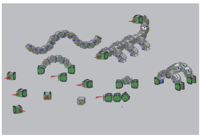
The EU-funded project SYMBRION (http://www.symbrion.eu) is aiming to de-velop a super-large-scale swarm of robots which is able to autonomously assemble to form 3D symbiotic organisms to perform tasks. The idea is to combine the advan-tages of swarm and self-reconfigurable robotics systems to investigate and develop novel principles of evolution and adaptation for robotic organisms from bio-inspired and evolutionary perspectives [7]. Each robot in such a system can either work au-tonomously or self-assemble into various morphologies when required, as shown in Figure 1. Unlike modular self-reconfigurable robotic systems such as PolyBot G3 [17], CONRO [11], M-TRAN III [9] and SuperBot [12], (see [3, 16] for a survey of such systems), in SYMBRION individual robots are independently mobile and will be able to autonomously aggregate and dock with each other. The robots will ini-tially form a 2D planar organism. Once the robots in the 2D planar organism have assumed the correct functionality, according to their position in the organism, the organism will lift itself from 2D planar configuration to 3D configuration and, with respect to locomotion, will function as a macroscopic whole. The aggregated organ-ism will also be able to disassemble and reassemble into different morphologies to fit the requirements of the task.
The morphologies of the organism that the robots can self-assemble into must be constrained by the specific hardware design of the individual robots. With only limited sensory capabilities, it is a challenge to coordinate the behaviours of a large number of robots in a decentralised manner in order that the robots can form some desired structures. A bio-inspired gradient based process has been widely used to to study the pattern growth problem in agent-based cell systems [10, 2, 15]. Various morphology control mechanisms have also been proposed for controlling different
Wenguo Liu and Alan F. T. Winfield
Bristol Robotics Laboratory, University of the West of England, Bristol, UK. e-mail: [email protected], [email protected]
Fig. 1: A vision of the SYMBRION project. Two types of robots, with different motion capability but compatible mechanical docking units, are proposed to be de-veloped in the system. All robots can explore the environment freely using their own sensing and actuators. Different structures can be formed when several robots physically connect to each other, such as a ‘snake’ like shape and a ‘scorpion‘ like shape shown here.
au-tonomous mobile robots. However, this chapter focuses on how specific structures can be formed based on the existing sensing and communication capabilities of the SYMBRION robot.
This chapter is organised as follows: Section 2 introduces the robot platform used in this study. Section 3 presents the controller design for each single robot. This section gives a detailed discussion about the local communication protocols and the behaviours for the robots. Section 4 discusses two different recruitment strategies for growing an organism. Section 5 verifies the morphology control mechanism in simulation and Section 6 concludes the chapter.
2 The SYMBRION robots and their docking sensors
(a)
TCRT1010 TSML1020 TCRT1010
TSML1020 TSML1020
TSOP36236
(b)
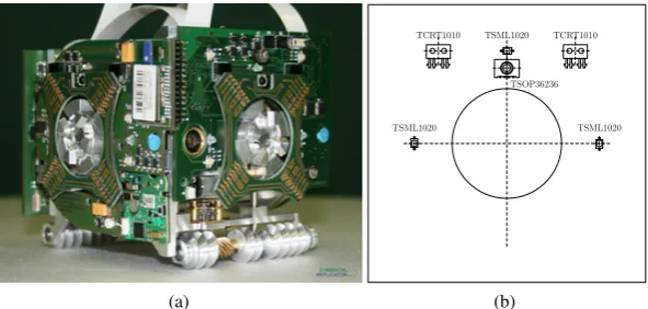
Fig. 2: a) The first generation prototype of a SYMBRION robot and, b) the place-ment of the IR sensors on each vertical side PCB.
Table 1: Infra-red sensors for autonomous docking
Sensors Quantity Range Purpose
Proximity sensor 8 15cm obstacle and robot detection Docking alignment sensor 8 25cm IR beacon signal detection
IR communication channel 4 150cm general communication duty and bearing detection
[image:3.595.154.450.292.433.2]axis. A rich set of sensors are proposed to be installed in the robot for environmental perception, locomotion and internal state monitoring purposes, see [6] for a full list. Four mechanical docking units, one on each vertical side, are installed on the robot to allow stable physical connections between robots. In addition, electrical contacts next to the docking units can be coupled automatically to provide inter-robot com-munication and power sharing busses between two connected robots. The docking units can handle misalignment in horizontal and vertical directions as well as rota-tion within certain ranges. This configurarota-tion gives the robots flexibility on either working as fully autonomous units with their own perception and actuation capabil-ity, or as a whole organism sharing the sensing, computation and energy cross the busses.
To achieve autonomous docking in a 2D planar environment, specific infrared (IR)-based sensing – including proximity detection and docking alignment detec-tion – and local communicadetec-tions circuits have been developed for the SYMBRION robot, see [8]. As shown in Table 1, Each robot is endowed with 8 proximity sensors, 8 docking alignment sensors and 4 channel local communications for autonomous docking, the maximum detection range for each function is about 15cm, 25cm and 150cm respectively. These sensors have the same placement on each side PCB of the robot, as shown in Figure 2(b). More specifically, two IR sensors (TCRT1010) have been placed symmetrically above and on either side of the docking unit (marked with a circle); one IR LED (TSML1020) is placed directly above the docking unit, while the other two LEDS are located on either side of the docking unit. These LEDs are used to emit different frequency signals for obstacle detection, docking alignment and communication. The IR sensors work for both obstacle detection and docking alignment detection. As for communications, one IR remote control re-ceiver (TSOP36236) is placed next to the IR LED on each side PCB. Note that the 4 channels of local communication can work simultaneously. By default they are all in “listening” mode; whenever one robot is broadcasting messages, another robot within range will receive the message with one or two adjacent channels, which provide the robot with an approximation of the direction of the signalling robot.
3 The Controller framework for autonomous morphogensis
1 2 5 6 4 3 7 8 A 1 2 5 6 4 3 7 8 B 1 2 5 6 4 3 7 8 1 2 5 6 4 3 7 8
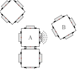
Fig. 3: A scenario of autonomous docking. Robot A is emitting some signals to recruit another robot. Robot B that detects the signals is trying to align with Robot A for docking.
robots need to be recruited. The beacon signals can only be detected by other robots at short range (15cm). They are used to guide the approaching robots to execute precise alignment towards the docking face. Once two robots are well aligned and close enough, a physical docking/locking process can be started. Upon the comple-tion of the locking process, the recruiting robot stops emitting beacon signals. To form required 2D structures, new robots in the partially assembled organism will be selected to recruit more robots following some rules. The same process is repeated until the specified structure is formed. Thereafter, the robots in the organism must determine collectively whether the current structure is suitable for the task. If not, a new shape must be selected; all or some of the robots must disconnect from the organism and a new cycle of self-assembly started until the organism can achieve its goal. A behaviour-based approach is adopted for the design of the morphogenesis controller as described in the following sections.
3.1 A finite state machine
as-LocateBeacon Flocking
Alignment Docking InOrganism Recruitment
Disassembly
Recover 1 2
3 4
5
6
7
8 9
10
11 11 12 11
13
[image:6.595.134.468.75.234.2]Swarm Mode Organism Mode
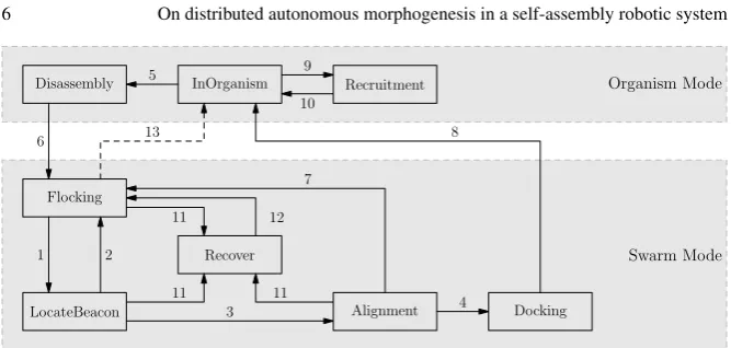
[image:6.595.195.406.297.445.2]Fig. 4: Robot finite state machine (FSM) for the autonomous morphogenesis con-troller
Table 2: Conditions causing state transitions
Number Description
1 docking message received
2 collision, or no docking message received 3 docking beacon signals detected 4 aligned and ready to dock 5 disassembly required 6 undocking completed
7 expelling message received, or docking signals lost 8 docking completed
9 recruitment required 10 recruitment completed 11 robot stalled
12 recover done
13 decision to become a seed robot
sociated with self-assembly or disassembly. As indicated with a dashed line, a robot in stateFlockingmay transfer to stateInOrganismand then to stateRecruitmentto start the self-assembly process – this is the seed robot (see section 3.3). Although only one seed robot can occur within one growing organism multiple seed robots may co-exist in the swarm.
3.2 Behaviours
Communication plays a crucial role on coordination of the behaviour for the robots when self-assembly is in progress. In the SYMBRION robots, two kinds of local communication are proposed to fulfil this purpose. When robots are inswarm mode, IR-based communication is used to self-organise the autonomous docking process. At this stage, robots simply broadcast some simple message tokens when required. Note that when transmitting messages, only one or two specific communication channels are used. Since the IR signals may be occluded and have a certain trans-mission angle and range, the number of candidate receivers is limited, as we would expect. To reduce the complexity of the communication protocols, five fixed mes-sage tokens, each of 1-Byte length, are broadcast by the robots when communication is required, as follows:
-MSG-Recruitment is to indicate that a recruitment process has started. The mes-sage is broadcast and repeated by the robots in stateRecruitment. It is used by other robots to locate the direction of a recruiting robot in longer range with less accuracy.
-MSG-InRange is transmitted by the robot in state LocateBeacon when it de-tects beacon signals (transmitted by one of the IR LEDs of a recruiting robot). The message is used to inform the recruiting robot to stop transmitting MSG-Recruitment messages.
-MSG-Expelling is broadcast by the robot in stateAlignmentto expel other com-petitors in order to make more room for docking alignment and thus reduce in-terference.
-MSG-DockingReady is sent by the robot in stateDockingwhen its docking unit is fully in position to the recruiting robot. It is used to inform the recruiting robot to stop emitting beacon signals and start to lock the docking units.
-MSG-UnDocked is sent by the robot in stateDisassemblywhen the undocking procedure is fully completed. The robot which was previously docked will re-ceive this message.
For robots inorganism mode, communication is implemented through the com-mon bus between two coupled docking units. Apart from the coordination and con-trolling of behaviour for the whole organism, which is beyond the scope of this study, the autonomous morphogenesis also requires sharing information among the partially assembled organism. To implement the recruitment strategies discussed later, the following essential information needs to be shared via the communication bus.
- Information about the current organism structures. The newly docked robots need to acquire this information from the recruiting robots such as the number of robots in the partially assembled organism, the final shape of the organism, etc. However, the message content will vary when different recruitment strategies are applied.
The behaviours of each state of the FSM can be defined as follows:
- InOrganism Robot remains static in the organism while monitoring the com-munication busses. When aMSG-NewRobotAttachedmessage is received from one of the channels, it checks whether it needs to switch to stateRecruitmentor Disassemblyfollowing certain rules. Then it sends theMSG-NewRobotAttached messages to other docked neighbour robots, excluding the one it received the message from.
- Recruitment Robot chooses one or several docking faces, based on the recruit-ment strategy, from which to emit beacon signals andMSG-Recruitment mes-sages at the same time. Once it detects aMSG-InRangemessage, it stops trans-mitting MSG-Recruitmentto avoid attracting too many robots. The robot per-forms a mechanism docking lock when theMSG-DockingReadymessage is re-ceived. It then moves to stateInOrganismand sendMSG-NewRobotDocked mes-sages to all connected robots.
- Disassembling Robot executes an action sequence to undock from the organism if only one of its docking units is connected. It then sends aMSG-UnDocked message to the robot previously connected and moves to stateFlocking. If more than one docking units are connected, it continues to wait.
- Flocking Robot wanders in the environment and searches for docking beacons. It avoids obstacles and other robots. WhenMSG-Recruitmentmessages are re-ceived it moves to stateLocateBeacon. This state is also a place holder for any other behaviours inswarm modewhich are not relevant to the self-assembly pro-cess. For example, robots in stateFlockingcan perform work and under certain conditions become seed robots.
- LocateBeacon Robot approximately locates the beacon using 4 IR communi-cation channels and moves in the direction of the beacon signals. If no MSG-Recruitmentmessages are received, or obstacles are detected, it transfers back to stateFlocking. If beacon signals are detected, it sends aMSG-InRangemessage and then moves to stateAlignment.
- Alignment Robot adjusts its headings and tries to minimise the misalignment of two docking units. It transmitsMSG-Expellingmessages repeatedly to expel competitors. However, if it detectsMSG-Expellingmessages from other robots, it exits to stateFlocking. Once two docking units are aligned and close enough (based on readings from the beacon detection sensors and proximity sensors), it transmits aMSG-DockingReadymessage and moves to stateDocking.
- Recover Whenever robot gets stalled with obstacles or other robots, it executes some action sequence to rescue itself. If succeeded, it moves to stateFlocking regardless its previous state.
3.3 The seed robots
The seed robot is defined as the robot that initiates the process of self-assembly for an organism. It is the first robot in the organism and is not recruited by other robot. Clearly, as all robots in the system have the same controller, any of them can choose to become a seed robot when certain conditions are satisfied. The seed robot will decide the initial shape of the organism the robots need to self-assemble into. It has the duty of monitoring the self-assembly process and notifying the completion of the construction within the formed organism. In case reshaping is required, the seed robot is also in charge of initiating the reshaping procedure. Note that multiple seed robots can co-exist in the overall system since multiple organisms may arise at the same time. However, each organism can only have one seed robot. A detailed explanation of how robots choose to become seed robots is outside the scope of this chapter, however, we anticipate that some environmental feature such as a wall judged by the robot too high to go around would trigger this transition.
3.4 Competition resolution
4 Recruitment strategies
To grow a specific organism shape from one seed robot, the right strategies have to be applied. In other words, the robots in the partially assembled organism must determine the location and timing at which a new robot needs to be recruited and connected. More specifically, the following questions need to be addressed: - which robots need to move from stateInOrganismto stateRecruitment; - which docking faces the recruiting robot needs to open to recruit new robots.
These problems are referred as recruitment strategies in this study. As there is no central control unit in the partially assembled organism, each robot in the developing organism have to autonomously decide the next steps in the self-assembly process.
4.1 Representation of organisms
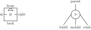
Before we can address the recruitment strategy a common representation for the pre-defined organism structures must be defined. During an autonomous docking process a recruiting robot is normally static while emitting the docking beacon sig-nals. Although each robot has four side docking units named front, left, back and right, the locomotion capability of a single robot dictates that robots will use their front side only to dock onto the recruiting robot. Therefore, for any connection be-tween two docking units in the organism, one and only one front side docking unit must be present. If each robot in the organism is treated as a node in a tree data structure where the “parent”, “lchild”, “mchild” and “rchild” of the node represent the front, left, back and right side of a robot respectively, as shown in Figure 5, then the whole organism in a 2D planar environment can be represented as a tree data structure in which each edge denotes a physical docked connection between two robots.
0
front
left right
back
0 parent
[image:10.595.222.381.474.527.2]lchild mchild rchild
Fig. 5: A robot and its graphical node counterpart. The hinge joint is on the left-right axis.
are complete different. Clearly, the start point for self-assembly of an organism, i.e. the seed robot, cannot be arbitrarily chosen. It must be the root node of its corre-sponding tree representation. In the following sections, two different recruitment strategies will be investigated based on this graphical representation.
0
1
2
3
4
5 6 7
8 9 10 11 0 1 2 3 4 5 6 7 8 9 10 11 (a) Organism 1
0
1
2
3
4
5 6 7
8 9 10 11 0 1 2 3 4 5 6 7 11 10 9 8
[image:11.595.180.421.165.465.2](b) Organism 2
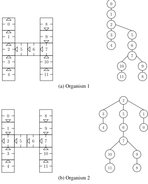
Fig. 6: Graphical representation of organism structures. Although two organisms have very similar 2D planar structures, the orientation difference for robots with ID ‘2’ leads to different 3D motion capability for these two organisms, when those robots bend their hinge joint.
4.2 Strategy 1 - single entry recruitment
to move into state Recruitment with only one docking face activated, at any one time. In other words, only one robot can be recruited to the organism every time – a single entry recruitment. Thus, the order in which robots attach to the organism can be retrieved by a pre-order walk of its tree representation. Take organism 1 shown in Figure 6(a) as an example, assume each node has been identified with an unique name, if the children of a node are visited in the order “mchild – lchild – rchild”, then the robots can be recruited to the organism in the order of list{0, 1, 2, 3, 4, 5, 6, 7, 10, 11, 9, 8}, namedsortedNodeList, where the first robot, No. 0, will act as a seed robot. Other robots in thesortedNodeListare recruited by their parent node one by one. The order that the robots move into theRecruitmentstate is in fact the order of the parent nodes of each node in the pre-order walk node list, i.e.{0, 1, 2, 3, 2, 5, 6, 7, 10, 7, 9}for organism 1. The recruitment side of each recruiting robot can also be easily retrieved from the tree representation. If we introduce an ordered pair “(Robot-ID, Recruitment-Side)”, then to grow organism 1, the order that the robots move to stateRecruitmentand their corresponding recruitment sides can be expressed as list{(0, 0), (1, 0), (2, 0), (3, 0), (2, 2), (5, 0), (6, 0), (7, 1), (10, 0), (7, 2), (9, 0)}, namedrecruitmentNodeList, where number 0, 1, 2 in the second element of each pair denote the Back, Left and Right side of a robot respectively. Similarly, for organism 2, sortedNodeList = {2, 5, 6, 7, 10, 11, 9, 8, 3, 4, 1, 0}, andrecruitmentNodeList={(2, 0), (5, 0), (6, 0), (7, 1), (10, 0), (7, 2), (9, 0), (2, 1), (3, 0), (2, 2), (1, 0)}. Listing 1 shows an algorithm to generate these two node lists recursively from the tree data structure of an organism.
Algorithm 1Generating two node lists recursively
Precedure: PreOrderTraversal (node)
Input: the root node of a tree 1: ifnode̸=ϕthen
2: sortedNodeList.push(node→id); 3: ifnode→GetParent()̸=ϕthen
4: RecruitmentNode rnode;
5: rnode.id⇐node→GetParent()→id; 6: fori=0to2do
7: if node == node→GetParent()→GetChildByIndex(i)then
8: rnode.side⇐i;
9: recruitmentNodeList.push(rnode); 10: end if
11: end for
12: end if
13: PreOrderTraversal (node→GetMiddleChild()); 14: PreOrderTraversal (node→GetLeftChild()); 15: PreOrderTraversal (node→GetRightChild()); 16: end if
Recruitment. Note that the robot in the organism will be allocated with unique ID only when it docks to the organism. Its identity is reset to null whenever it undocks from the organism. We also assume that all robots store the same information about the organisms, i.e. pairs ofsortedNodeListandrecruitmentNodeList.
Algorithm 2Single entry recruitment strategy for robots inorganism mode
Behaviour: in stateInOrganism
1: ifaMSG NewRobotAttachedreceivedthen
2: propagate theMSG NewRobotAttachedto connected neighbours, except the one it received the message from;
3: num_robots_inorganism⇐num_robots_inorganism+ 1;
4: end if
5: if its ID matches with the ID from recruitmentNodeList which is indexed by num robots inorganismthen
6: enable the corresponding docking channel and start to emit beacon signals; 7: move to stateRecruitment;
8: end if
Behaviour: in stateRecruitment
9: ifaMSG DockingDonereceived from the recruiting channelthen
10: send information about the current developing organism to newly docked robot;
11: propagate theMSG NewRobotAttachedto connected neighbours, except the newly docked one;
12: stop emitting beacon signals;
13: num_robots_inorganism⇐num_robots_inorganism+ 1;
14: move to stateInOrganism;
15: else ifaMSG InRangereceived from the recruiting channelthen
16: stop broadcastingMSG Recruitment; 17: reset internal timerT1;
18: else ifT1is upandit is the time slot for sending recruitment signalsthen 19: broadcastMSG Recruitmentvia corresponding recruiting channel; 20: end if
vari-ablenum_robots_inorganismby 1, now 3. Next, robot “6” in stateInOrganism will be matched as the recruiting robot from therecruitmentNodeList. The process continues until all robots’ internal variablenum_robots_inorganismis equal to the size of thesortedNodeList.
4.3 Strategy 2 - multiple entries recruitment
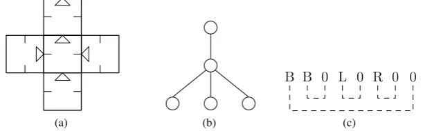
The second strategy for growing an organism from one seed robot is to allow mul-tiple robots to be recruited to the organism at the same time, notwithstanding the potential interference and competition that may arise due to the multiple IR light sources. The idea is to activate all docking faces of the developing organisms for docking where new robots need to be recruited. This implies no limitation will be applied on the number of robots moving to stateRecruitmentand on the number of docking units that one robot is allowed to open for recruiting new robots. As the robots in the swarm modebehave independently, the order that the robots are re-cruited to the organism are unlikely to remain the same in subsequent self-assembly of the same organism. To implement the idea of multiple entries recruitment, how the organism structures are stored in the robot and are transferred between robots needs to be addressed first. Unlike the ID-based node lists introduced in the first strategy, here the tree representation of an organism will be described with a well-formed parenthesis symbol sequence over{‘B’, ‘L’, ‘R’, ‘0’}, where ‘B’, ‘L’ and ‘R’ stand for “back”, “left” and “right” respectively. The symbol sequence is anno-tated with a nested structure, corresponding to the edges of the tree. The length of a symbol sequence is two times the number of edges of the tree, of which half are filled with character ‘0’. Figure 7 shows an example of a 2D organism structure and its symbol sequence.
(a) (b)
B B 0 L 0 R 0 0
(c)
Fig. 7: (a) A simple ‘cross’ 2D organism, (b) its tree representation and (c) the symbol sequence notation.
[image:14.595.148.454.453.548.2]in the opposite direction. A recursive algorithm for obtaining the symbol sequence from the tree representation of an organism is shown in Listing 3.
Algorithm 3Generating the symbol sequence recursively
Precedure: PreOrderTraversal (node, side)
Input: a tree node and one of its child side (∈{MIDDLE, LEFT, RIGHT}) 1: ifnode̸=ϕthen
2: ifnode→GetParent()̸=ϕthen
3: symbolSequence.push(GetSymbolBySide(side)); 4: end if
5: PreOrderTraversal (node→GetMiddleChild(), MIDDLE); 6: PreOrderTraversal (node→GetLeftChild(), LEFT); 7: PreOrderTraversal (node→GetRightChild(), RIGHT); 8: ifnode→GetParent()̸=ϕthen
9: symbolSequence.push(‘0’); 10: end if
[image:15.595.152.467.139.291.2]11: end if
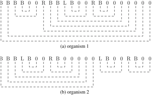
Figure 8 then shows two symbol sequences for the organism 1 and 2 introduced in previous section. Clearly, the symbol sequence notation yields a very compact
for-B for-B for-B for-B 0 0 R B B L B 0 0 R B 0 0 0 0 0 0 0
(a) organism 1
B B B L B 0 0 R B 0 0 0 0 0 L B 0 0 R B 0 0
(b) organism 2
Fig. 8: Symbol sequences of example organisms. The dashed line that connects two symbols indicates a corresponding edge in its tree representation counterpart.
[image:15.595.172.434.351.514.2]Similar to the tree representation of section 4.1, a symbol sequence may in-clude up to three branch1sequences, namely left, back and right branch respectively. For example, organism 1 has only one back branchBBBB00RBBLB00RB0000000
while organism 2 has a back branchBBBLB00RB00000, a left branchLB00and a right branchRB00. Along with the symbol sequence representation, an implemen-tation of the multiple entries recruitment strategy is shown in Algorithm 4.
Algorithm 4Multiple entries recruitment strategy for robots inorganism mode
Behaviour: in stateInOrganism
1: ifnew symbol sequence information receivedthen
2: extract the branches from the symbol sequence; 3: fori=0to2do
4: ifGetBranch(i)̸=ϕthen
5: enable the corresponding docking channel and start to emit beacon signals; 6: end if
7: end for
8: move to stateRecruitment; 9: end if
Behaviour: in stateRecruitment
10: fori = 0to2do
11: ifaMSG InRangereceived from channel ithen
12: stop broadcastingMSG Recruitment; 13: reset the internal timerTi;
14: else ifTiis upandit is the time slot for sending recruitment signalandthe corresponding recruiting channel is not connectedthen
15: broadcastMSG Recruitmentvia corresponding channel; 16: end if
17: ifaMSG DockingDonereceived from channel ithen
18: stop emitting beacon signals from channel i;
19: send a branch symbol sequence, if it exists, to corresponding newly docking robot; 20: ifall required docking faces are connected with new robotsthen
21: move to stateInOrganism; 22: end if
23: end if
24: end for
When the strategy is applied, the newly docked robot may receive a new sym-bol sequence from the recruiting robot it is docked to. If yes, this robot moves to state Recruitmentand enables the docking faces where the corresponding branch sequences exist. For the robot in stateRecruitment, whenever a new robot docks to it, it sends a symbol sequence, which is generated by removing the first and the last characters of the corresponding branch sequence, to the newly docked robot. Note that the transferred symbol sequence can be an empty string if the corresponding branch includes only one edge. Once all required docking faces are docked with new robots, it moves to stateInOrganism. The process repeats until the organism is formed. Note that in this case only the seed robot has the completed symbol
quence which represents the final organism structure, while all other robots in the organism store only sub sequences which include the robot itself and its children nodes. For clarification, take organism 2 as an example: The seed robot (robot “2”) first moves to stateRecruitmentwith its left, back and right docking faces enabled to recruit new robots, since its symbol sequence has one left, one back and one right branch. When a new robot (robot “5”) docks to its back side, the seed robot will send a symbol sequenceBBLB00RB0000 to robot “5”. Robot “5” then moves to Recruitmentstate with the back side docking faces enabled as there is no left and right branch in the symbol sequence ofBBLB00RB0000. When robot “6” docks to robot “5”, it gets a symbol sequence ofBLB00RB000. Again, robot “6” enables its back side docking face only for recruiting new robots. Similarly, robot “7” gets a symbol sequence ofLB00RB00from robot “6” and recruits new robots with its left and right docking face, robot “9” and “10” getB0from robot “7”, robot “1” and “3” getB0from robot “2”. When robot “4” docks to robot “3”, it gets an empty symbol sequence from robot “3” hence stays in state InOrganism. The same rule applies for robot “0”, “8” and “11”. Note that this strategy does not require the robot in the organism to be allocated with a unique name, which is another advantage of the multiple entries recruitment strategy.
5 Verification in simulation
...
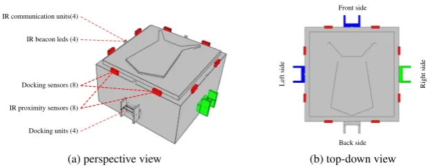
Docking units (4) .
Docking sensors (8) .
IR beacon leds (4) . IR communication units(4) .
IR proximity sensors (8) ....
(a) perspective view
... Front side .
Left
side
.
Right
side
.
Back side
[image:17.595.145.457.387.508.2](b) top-down view
Fig. 9: A 2.5 dimensional SYMBRION robot model in Stage simulation.
robot can move in the arena using two differentially driven wheels (not shown in Figure 9). Four simplified docking units on each vertical face of the robot simulate mechanical docking. As the morphogenesis approach discussed in the study takes place exclusively in a 2D environment, neither the hinge driver of the robot nor the physics needs to be simulated.
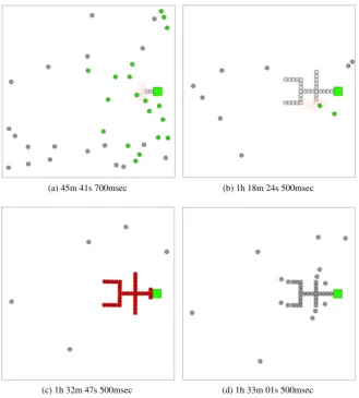
(a) 45m 41s 700msec (b) 1h 18m 24s 500msec
(c) 1h 32m 47s 500msec (d) 1h 33m 01s 500msec
Fig. 10: Screenshots from simulation using single entry strategy, the first robot is attached to the large box power socket at time 42m 52s 600msec. The organism is completed at time 1h 32m 30s 600msec.
[image:18.595.137.467.172.538.2]are self-assembling into a complex 2D shape with 4-way and 3-way joints, and right angles, using the single entry recruitment strategy. To trigger the start of the morphogenesis process a large box acting as a “power socket”, emitting IR signals which can be detected by the docking sensors of a robot, is placed in the arena. The first robot that finds the box becomes the seed robot and docks with the box. It then chooses, at random, one organism shape from its set of pre-defined struc-tures and executes the recruitment strategy described in previous sections to recruit other robots and hence initiate the new structure. To further test the controller, once the organism has completely formed (Figure 10(c)), all robots in the organism are switched to stateDisassemblyfor re-shaping. Figure 10(d) shows that the organism has started disassembling. After all robots are disconnected from the organism, the “power socket” starts to transmit IR signals again and the cycle is repeated. Each time, the seed robot randomly chooses a pdefined organism and starts the re-cruitment procedure. Figure 11 shows some different 2D structures the robots have constructed within one single simulation run. As the IDs of the robots in the or-ganism are dynamically allocated when they dock, the particular individual robots that make up the organism vary each cycle. Thus the same robot may play different roles, depending on its position, in different organisms.
The same experiments have been performed using the multiple entry recruitment strategy. Figure 12 shows screenshots from the simulation in which the robots are trying to self-assemble to the same shapes as before. Clearly, this strategy allows more than one robot to recruit new robots into the developing organism. These are marked with dark colours in Figure 12. The order in which the robots move to state Recruitmentdepends on the shapes and the progress that the organism grows. As parallel docking from different positions is enabled, the organism grows much faster than with single entry recruitment strategy: the completion time is now around 19 minutes compared to 50 minutes.
6 Discussion and conclusion
(a) a simple shape (b) a six leg structure with tail
[image:20.595.137.464.78.462.2](c) a four leg ‘H’ structure
Fig. 11: A selection of different 2D planar structures formed in simulation using single entry recruitment strategy.
in-(a) 11m 10s 200msec (b) 15m 13s 700msec
[image:21.595.138.468.83.459.2](c) 16m 54s 600msec (d) 20m 26s 800msec
Fig. 12: Screenshots from simulation using multiple entries recruitment strategy. The robots marked with dark colour are in stateRecruitment. The first robot is at-tached to the large box at time 10m 30s 100msec. The organism is completed at time 29m 38s 300msec.
cludes the robot itself and all its descendants nodes. Therefore, there is no need to use an unique name to identify each robot in the organism.
and no cycles. Not surprisingly, as shown in the simulation, less time is required to develop an 2D organism when the second strategy is applied so that parallel docking is enabled. However, the gap between completion time, when different strategies are applied, may vary with the organism shapes the robots are trying to form. For exam-ple, it will take very similar time for the robot to grow a snake shape organism no matter which strategy is used, as in both cases only one robot can be recruited into the organism at a time. Although the system with the multiple entries strategy can, in general, achieve better performance in term of time efficiency towards develop-ing a specific organism structure, higher interference and competition can emerge, resulting in a longer average time to recruit one robot from one specific location of the developing organism. Thus, the right strategy needs to be chosen carefully considering the performance metric of greatest concern.
In conclusion, the controller framework and the morphological control mech-anism presented in this study leads to a fully distributed approach towards au-tonomous morphogenesis in the proposed self-assembly robotic system. Although this study considers only the scenario that the robots are constructing 2D planar or-ganisms. The work will be expanded in the direction of both theswarm modeand organism modeusing the same framework. For example, only very simple disassem-bly strategies have been implemented in this work. To improve the energy efficiency of the re-shaping procedure, more complex disassembly strategies need to be inves-tigated in future work. Note also that at the time of writing the algorithm is not fault tolerant and there are many ways in which faults might disrupt the self-assembly process including, for instance, mechanical failure of the docking mechanism or failure of the power or communications busses across the docking mechanism. With real hardware operating over extended periods and multiple robots the probability of such faults is likely to be high. Thus planned work also includes extending the mor-phogenesis algorithm so that if faults are detected during self-assembly, the process modifies itself to compensate for those faults.
Acknowledgements The SYMBRION project is funded by the European Commission within the work programme Future and Emergent Technologies Proactive under grant agreement no. 216342.
References
1. Christensen, A., O’Grady, R., Dorigo, M.: Swarmorph-script: a language for arbitrary mor-phology generation in self-assembling robots. Swarm Intelligence2(2), 143–165 (2008). DOI 10.1007/s11721-008-0012-6
2. Doursat, R.: Organically Grown Architectures: Creating Decentralized, Autonomous Sys-tems by Embryomorphic Engineering,Understanding Complex Systems, vol. 21, pp. 167–199. Springer Berlin / Heidelberg (2008). DOI 10.1007/978-3-540-77657-4 8
3. Gross, R., Dorigo, M.: Self-assembly at the macroscopic scale. Proceedings of the IEEE96(9), 1490–1508 (2008). DOI 10.1109/JPROC.2008.927352
5. Guo, H., Meng, Y., Jin, Y.: A cellular mechanism for multi-robot construction via evolution-ary multi-objective optimization of a gene regulatory network. Biosystems98(3), 193 – 203 (2009). DOI DOI: 10.1016/j.biosystems.2009.05.003
6. Kernbach, S., Meister, E., Scholz, O., Humza, R., Liedke, J., Ricotti, L., Jemai, J., Havlik, J., Liu, W.: Evolutionary robotics: The next-generation-platform for on-line and on-board arti-ficial evolution. In: Proceedings of IEEE congress on Evolutionary Computation, pp. 1079– 1086. Trondheim, Norway (2009)
7. Levi, P., Kernbach, S. (eds.): Symbiotic Multi-Robot Organisms: Reliability, Adaptability, Evolution. Springer (2010)
8. Liu, W., Winfield, A.: Implementation of an IR approach for autonomous docking in a self-configurable robotics system. In: T. Kyriacou, U. Nehmzow, C. Melhuish, M. Witkowski (eds.) Proceedings of Towards Autonomous Robotic Systems, pp. 251 – 258 (2009) 9. Murata, S., Kakomura, K., Kurokawa, H.: Toward a scalable modular robotic system. IEEE
Robotics Automation Magazine14(4), 56–63 (2007). DOI 10.1109/M-RA.2007.908984 10. Nagpal, R.: Programmable self-assembly: Constructing global shape using
biologically-inspired local interactions and origami mathematics. Ph.D. thesis, Massachusetts Institute of Technology (2001)
11. Rubenstein, M., Payne, K., Will, P., Shen, W.M.: Docking among independent and autonomous conro self-reconfigurable robots. In: Proceedings of IEEE International Conference on Robotics and Automation, vol. 3, pp. 2877–2882 (2004). DOI 10.1109/ROBOT.2004.1307497
12. Salemi, B., Moll, M., Shen, W.M.: SUPERBOT: A deployable, multi-functional, and modular self-reconfigurable robotic system. In: Proceedings of Intenational Conference on Intelligent Robots and Systems, pp. 3636 – 3641. Beijing, China (2006)
13. Støy, K.: Using cellular automata and gradients to control self-reconfiguration. Robotics and Autonomous Systems54, 135–141 (2006)
14. Vaughan, R.: Massively multi-robot simulation in Stage. Swarm Intelligence2(2-4), 189–208 (2008). DOI 10.1007/s11721-008-0014-4
15. Werfel, J.: Biologically realistic primitives for engineered morphogenesis. In: the Seventh In-ternational Conference on Swarm Intelligence (ANTS2010), pp. xxx–xxx. Springer, Belgium (2010)
16. Yim, M., WHITE, P., PARK, M., SASTR, J.: Modular self-reconfigurable robots. Encyclope-dia of Complexity and Systems Science (2009)