© 2019, IRJET | Impact Factor value: 7.211 | ISO 9001:2008 Certified Journal | Page 6712
Stability Enhancement using Power System Stabilizer with
Optimization Algorithm based PID Controller
R. Kavi priya1, Dr.R.Rajeswari2
1M.E IIyear, , Department of EEE, Government college of Technology, Coimbatore, India. 2 Associate Professor, Department of EEE, Government college of Technology, Coimbatore, India.
---***---Abstract - This paper proposes an intelligent optimization technique using Power System Stabilizer based hybridization with PID controller to enhance stability, in power system. PSS with PID Controller is used to damp inter area oscillations caused due to low frequency electro mechanical oscillation. The problem of PID-PSS design is transformed as an optimization problem based on performance index based Integral Absolute Error(IAE)where, Moth Flame Optimization(MFO) Algorithm is employed to obtain the optimal controller parameters .The performance of the system with PSS based PI,PD,PID controller is studied and robustness of controller is tested on a Single Machine Infinite Bus (SMIB) system under different disturbances in power system. By Simulation, results show the effectiveness of PSS and PID performance for enhancement of power system stability. The functionality of the proposed control strategy is verified using Matlab/Simulink
Key Words: PID, damping oscillation, power system stabilizer
1.INTRODUCTION
Power plant consists of numerous synchronous generators which are planned to convert the mechanical energy to electrical energy which are supplied to the consumers. As there is an increase in the range of customer’s area per unit, the load on the power system also increases. Due to this there is instability in transmission of power. The dilemma of strength of steadiness is posed in a stern mode to promise a fine process of the generating system, and to damp the dilemma of oscillations. In the Electromechanical systems by recovering the damping of the system (steadiness), for these purposes signals stabilizers are introduced into the excitation system via its Terminal voltage. These helpful signals can turn out the torques in the section with the speed variation of the generator for compensating for the section delay introduced by the excitation system.
The power system stabilizers are beneficial in terms of cost and efficiency, are the usual means, not only to eliminate the negative effects of Voltage regulators, but also for damping electromechanical oscillations and steadiness of the system. The main purpose of PSS based PID is to produce an appropriate torque on the mechanical part of the generator and to supply the better damping of power system. The PSS based PID design has formulated an optimization problem based on various performance indices. To prove the applicability of this design, it has been validated on a SMIB power system under different values of disturbances. The advantage of this method is that the system excitation is going to be powerful to insert effective irrespective of disturbances. During transient condition the stabilizing signal is being produced by PSS. Power system stabilizer is a combination of lead lag compensator, wash out filter and KPSS. It shows promise in many controlled environments that suffer from the classical problems of overshoot and resonance.
This article is organized as follows. Section 2 presents the description of a (SMIB) power system. 3. Role of power system stabilizer 4. Controlling mechanism by PID controller 5. Simulation and results 6. Conclusion of proposed work
II. POWER SYSTEM
© 2019, IRJET | Impact Factor value: 7.211 | ISO 9001:2008 Certified Journal | Page 6713 Figure.1. Heffron–Phillips block diagram for SMIB power system.
To calculate the values of gain, the torque, terminal voltage and the stimulation coil equations should be liberalized. And by eliminating the Δiqs and the Δids and rewriting the equations on the basis of ΔE′q and Δδ, the coefficients are calculated. Therefore, the m o d i f i e d constants K can now be computed based on l o c a l measurements only. In this model, as Vs is not constant during linearization, three additional constants K1 to K3 are introduced at the torque, field voltage and terminal voltage junction points as shown in Fig.2. The action of the PSS is effective through the transfer function block GEP(s) as shown in Fig.2 between the electric torque and the reference voltage input with variation in the machine speed assumed to be zero.
The expression for the transfer function GEP(s) is given by equation(1)
[image:2.595.47.555.49.266.2]Where EXC(s) is the transfer function of the excitation system. It can be of any exciter, as system operational conditions modification, the gain and phase characteristics of the transfer function GEP(s) change. Ideally, the PSS transfer function should be the reciprocal of GEP(s) for providing a prescribed amount of damping with speed input. This would be strictly performing lead operation, which is not physically realizable. A sensible approach is to own a lead-lag circuit that gives the adequate compensation over the specific variation of frequencies in the range of (0.1-2) Hz. Using the modified K constants, stabilizers are designed using the tuning. The stabilizer considered is a simple lead-lag compensator with a washout filter.
Table 1 Time Constant
Parameter Magnitude
Lead Time constant, T1 0.5 Lag Time constant, T2 0.05 Lead Time constant, T3 0.5 Lag Time constant, T4 0.05 Wash out Time Constant,
Tw
10
© 2019, IRJET | Impact Factor value: 7.211 | ISO 9001:2008 Certified Journal | Page 6714 Table 2 Gain constants
III. POWER SYSTEM STABILIZER (PSS)
A power system is said to be stable if it remains in a state of functional equilibrium under normal operating conditions and regain to an acceptable state of equilibrium after being subjected to a disturbance.
Figure.
2
. Functional block diagram of a synchronous generator excitation control systemSecurity of the facility system depends on its ability to survive any disturbances, which can occur with none interruption within the services. Figure.3 shows the practical diagram of a typical excitation system for an outsized synchronous generator. For the effective damping of oscillations of the rotor/turbine shaft, power system stabilizers are used. The improvement of small signal stability could also be achieved through the facility system stabilizers. The input signal to the PSS may be rotor speed, rotor angle, accelerating power, or a combination of these signals. The output signal of PSS is used as a supplementary stabilizing signal. Any stabilizing signal should turn out a torsion element in section with ∆ω, so positive damping could also be made.
[image:3.595.227.389.532.581.2]IV. PI CONTROLLER
Figure 3 shows the block diagram of PSS based PI controller. Proportional-plus-integral controller consist of two terms producing an output which one is proportional to the input signal and other proportional to the integral of input signal. It improves the relative stability and steady state tracking accuracy.
Figure.3.Block diagram of PSS-PI controller PD CONTROLLER
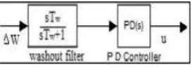
Proportional- derivative controller produces an output which consists of two terms, where one is proportional to input signal and other proportional to the derivative of input signal. The PD controller increases the damping of the system which results in reducing the peak overshoot. Figure 2 shows the block diagram of PSS based PD controller.
Figure.4.Block diagram of PSS-PD controller
K1 1.0749 K2 1.2576
K3 0.3072 K4 1.7124
[image:3.595.213.350.663.711.2]© 2019, IRJET | Impact Factor value: 7.211 | ISO 9001:2008 Certified Journal | Page 6715 PID CONTROLLER
PID controller stabilizes the gain, reduces the steady state error and peak overshoot of the system. Figure 3 shows the block diagram of PSS based PID controller.
Figure.4.Block diagram of PSS-PID controller V. PROPOSED ALGORITHM
In the proposed MFO algorithm, it’s a population-based algorithm. Where candidate solutions are moths and the problem’s variables are the position of moths in the space. Therefore, the moths can fly in 1-D, 2-D, 3-D, or hyper dimensional space with changing their position vectors. Since the moths and flames are both solutions. The difference between them is the way we treat and update them in each iteration. The moths are actual search agents that move around the search space, whereas flames are the best position of moths that obtains so far.
A logarithmic spiral as the main update mechanism of moths in this paper. However, any types of spiral can be utilized here subject to the following conditions:
Spiral’s initial point should start from the moth Spiral’s final point should be the position of the flame.
Fluctuation of the range of spiral should not exceed from the search space.
Considering these points, I defined a logarithmic spiral for the MFO algorithm as follows:
Spiral movement is the main component of the proposed method because it dictates how the moths update their positions around flames. The spiral equation allows a moth to fly “around” a flame and not necessarily in the space between them.
Therefore, the exploration and exploitation of the search space can be guaranteed. The logarithmic spiral, space around the flame, and the position considering different t on the curve are illustrated as follows
Figure.5. Logarithmic spiral
© 2019, IRJET | Impact Factor value: 7.211 | ISO 9001:2008 Certified Journal | Page 6716
The MFO algorithm is three-tuple that approximates the global optimal of the optimization problems and defined as follows:
I function that generates a random population of moths and corresponding fitness values.
P function, which is the main function, moves the moths around the search space. This function received the matrix of M and returns its updated one eventually.
T function returns true if the termination criterion is satisfied and false if the termination criterion is not satisfied With I, P, and T, the general framework of the MFO defined.
VI. SIMULATION RESULTS AND DISCUSSION
[image:5.595.204.398.280.456.2]In order to demonstrate effectiveness of proposed PSS based PID, obtained dynamic responses are obtained by employing PID-PSS. It is clear from Fig. 7 - 8 that the deviation profiles obtained by applying PSS based PI,PD,PID are significantly damped with minimum peak error, the shortest settling time, and zero steady state error. It means that surpassing improvement in damping characteristics and stability measures is obtained by employing the PSS based PID.
Figure.6. Simulation of PSS-PID
Simulation of PSS based PID controller in an SMIB system with AVR exciter, field circuit, inertial load, with mechanical and electrical torque, PID provides a stabilizing signal to SMIB system. Kp, Ki, Kd are values of PID controller, each value of gain is used to determine the waveform. Values of PID control play a vital role in determining overshoot, peak time, settling time. The fractional constants µ and are not integer ,they detect time of differentiation and integration.
Figure .7. Simulation with PSS-PI controller
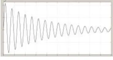
[image:5.595.207.388.544.640.2]© 2019, IRJET | Impact Factor value: 7.211 | ISO 9001:2008 Certified Journal | Page 6717 Figure .8. Simulation with PSS-PD controller
SMIB system with PSS –PD controller as shown in fig 8 ,derivative control plays a vital role in reducing peak overshoot and damping out oscillations.
Figure .9. Simulation with PSS-PD controller
SMIB system with PSS –PID controller as shown in fig 9 ,integral and derivative control plays a vital role in reducing peak overshoot and damping out oscillations and attaining equlibrium point.
VII. PERFORMANCE INDICES
The common Performance indices are used in practice is as below, 1) Integral Square Error ISE=∫e 2 (t)dt
2) Integral of the absolute magnitude of error IAE=∫│e (t)│dt 3) Integral Time-absolute error ITAE=∫ t.│ e (t) │dt
4) Integral Time-Square error (ITSE) ITSE=∫ e2 (t) dt
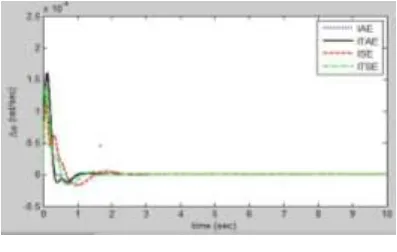
[image:6.595.201.400.578.704.2]Here e(t) is the error response of a system. Generally limit of integration is from 0 to ∞ but integration up to infinity is not practical and hence limit ∞ is replaced by T which is chosen sufficiently large so that e(t) for t >T is negligible.
Figure .10 Performance indices VIII.CONCLUSION
© 2019, IRJET | Impact Factor value: 7.211 | ISO 9001:2008 Certified Journal | Page 6718
Performance of controller are verified under sever disturbances. Since the PSS based PID outperforms the former stabilizers to obtain superior dynamic performance and to give more robustness to the uncertainties. Future scope of this research can be directed towards application of FOPID controller in flexible ac transmission system (FACTS)- based power oscillation damping (POD) controllers and its coordinated design with the FOPID-PSS.
APPENDIX:
The parameters of the studied SMIB power system are taken from literature [1]as below: Common system parameters:
Rated (Base) operating frequency (xb) = 314 rad/s.
Rated complex power (Sb) = 160 MVA. Rated voltage (Vb) = 15 kV.
Synchronous generator parameters
Synchronous d-axis reactance (Xd) = 1.7 p.u.
Synchronous q-axis reactance (Xq) = 1.64 p.u. Transient d-axis reactance (X0d) = 0.245 p.u. Field open circuit time constant (T0do) = 5.9 s.
Generator moment of inertia (H) = 2.37. Damping coefficient (D) = 0. Voltage regulator – exciter parameters
Exciter gain constant (KA) = 50.
Voltage regulator time constant (TA) = 0.05 s.
Transmission line parameters
Transmission line resistance (Re) = 0.02p.u. Transmission line reactance (Xe) = 0.4 p.u.
Nominal operating point
Real power (P) = 136 MW.
Reactive power (Q) = 83.2 MVAR.
Terminal voltage (Vt) = 17.3 kV \16.6.
Infinite bus voltage (Vinf) = 15 kV \0. Rotor angle (d) = 49.16.
REFERENCES:
[1] Anderson PM, Fouad AA. Power system control and stability. IEEE Press; 1994. [2] Kundur P. Power system stability
and control. McGraw-Hills; 1994.[2]Demello FP, Concordia C. Concepts of synchronous machine stability as effected by excitation control. IEEE Trans Power Apparatus Syst 1969;PAS88(4).
[3]Talaq J. Optimal power system stabilizers for multi machine systems. Int J Electr Power Energy Syst (IJEPES) 2012;43:793–803.
© 2019, IRJET | Impact Factor value: 7.211 | ISO 9001:2008 Certified Journal | Page 6719
[5]Nechadi, Harmas MN, Hamzaoui A, Essounbouli N. A new robust adaptive fuzzy sliding mode power system stabilizer. Int J Electri Power Energy System
[6]Abd-Elazim SM, Ali ES. A hybrid particle swarm optimization and bacterial foraging for optimal power system stabilizers design. Int J Electri Power Energy Syst March 2013;46:334–41].
[7]Verle M. PIC Microcontrollers-Programming in C, mikroElektronika; 2009.Verle M. PIC Microcontrollers, mikroElektronika; 2008.Ibrahim. Microcontroller based applied digital control. John Wiley & Sons; 2006.
[8]Lee S, Li Y, Kapila V. Development of a Matlab-Based Graphical User Interface Environment for PIC Microcontroller Projects. In: Proceedings of the 2004 ASEE, Education Annual Conference & Exposition; 2004.
[9]IEEE Std. 421.5, IEEE Recommended Practice for Excitation System Models for Power System Stability Studies, IEEE Power Engineering Society; 2005.
[10]Said S, Kahlout O, Ellithy K. First prize award received by Qatar University at IEEE PES Student Poster Contest at Transmission &Distribution Conference, Orlando, FL; May 2012, <http://ewh.ieee.org/soc/pes/sasc/awards.html>.
[11]He Ping, Wen Fushuan, Ledwich Gerard, Xue Yusheng, Wang Kewen. Effects of various power system stabilizers on improving power system dynamic performance. Int J Electri Power Energy Syst (IJEPES) 2013;46:175–83.
[12]Gurrala G, Sen I. Power system stabilizers design for interconnected power systems. IEEE Trans Power Syst 2010;25(2).