Microstructural Evolution in Pure Aluminum in the Early Stages
of Processing by High-Pressure Torsion
Cheng Xu
1;*1, Zenji Horita
2;*2and Terence G. Langdon
1;31
Departments of Aerospace & Mechanical Engineering and Materials Science University of Southern California, Los Angeles, CA 90089-1453, U.S.A.
2Department of Materials Science and Engineering, Faculty of Engineering Kyushu University, Fukuoka 819-0395, Japan 3Materials Research Group, School of Engineering Sciences University of Southampton, Southampton SO17 1BJ, U.K.
Measurements were taken to evaluate the evolution of homogeneity in disks of high-purity aluminum in the early stages of processing by high-pressure torsion. The results demonstrate that samples processed through 1/4 or more whole revolutions exhibit microhardness values which are generally higher in the centers of the disks than at the edges whereas after 1/8 turn the hardness is higher at the edge than in the center. It is shown that all of the hardness measurements are mutually consistent and they scatter around a unique curve when plotted against the equivalent strain. The measurements of hardness are supplemented by microstructural observations which provide evidence of a gradual evolution in the microstructure with increasing strain from an initial formation of subgrains to an array of ultrafine grains separated by boundaries having high angles of misorientation. [doi:10.2320/matertrans.MB200910]
(Received August 3, 2009; Accepted October 2, 2009; Published November 26, 2009)
Keywords: hardness, high-pressure torsion, homogeneity, severe plastic deformation, ultrafine grains
1. Introduction
Processing through the application of severe plastic deformation is now an accepted procedure for producing polycrystalline metals with exceptionally small grain sizes.1) An example of this approach is high-pressure torsion (HPT) where a sample, generally in the form of a thin disk, is subjected to an applied pressure and concurrent torsional straining.2) An important advantage of HPT is that it is capable of introducing exceptional grain refinement and producing materials with grain sizes in the lower submi-crometer range or even in the nanometer range.
When a disk is processed by HPT, the equivalent strain imposed by torsional straining, "eq, varies across the disk through a simple relationship of the form3)
"eq¼
1 ffiffiffi 3
p r
h ð1Þ
whereris the distance from the center of the disk, is the total rotational angle imposed on the disk in radians andhis the thickness of the disk. It follows from eq. (1) that the strain is a maximum at the periphery of the disk and reduces to zero at the disk center. This means that, in principle at least, it is reasonable to anticipate that the strain imposed in processing by HPT is very inhomogeneous with little or no strain introduced in the central region.
Early experiments on polycrystalline Ni confirmed that there were higher values of the microhardness, indicative of larger strains and more refined microstructures, around the edges of the HPT disks but with lower microhardness values in the disk centers. However, detailed experiments showed that the hardness values across the disks became more homogeneous when the pressure imposed during torsional
straining was increased.4) The gradual evolution towards a more homogeneous structure in disks of Ni was later demonstrated by constructing plots of the hardness values over the disk surfaces after processing through different numbers of torsional revolutions and different applied pressures and these plots demonstrated greater homogeneity at larger numbers of revolutions and higher applied pres-sures.5) To date, several reports are now available on the variations of hardness across HPT disks for a range of metals including Al and aluminum alloys,6–8) Cu,9–11) Ni12) and steel.13)
It is possible to achieve an excellent pictorial representa-tion of the hardness distriburepresenta-tions introduced in HPT by taking large numbers of individual hardness measurements follow-ing rectilinear grid patterns on the disk surfaces and then plotting these data in the form of color-coded contour maps. This approach was first introduced for high-purity Al14)and subsequently the same approach was applied to an aluminum Al-6061 alloy,15)Cu and Cu-Zn alloys16)and high-purity Al processed by HPT using strain reversals.17)
The results from these experiments revealed a clear dichotomy between different materials. First, and as antici-pated from application of eq. (1), the hardness values tended to be higher at the disk peripheries and lower at the disk centers in the Al-6061 alloy15) and in pure Cu and the Cu-Zn alloys.16) Second, and contrary to eq. (1), the hardness values in high-purity Al were initially higher in the centers of the disks and lower at the edges.14) However, both sets of materials showed a gradual evolution towards a reason-ably homogeneous distribution of hardness values when the HPT processing was continued through larger numbers of turns.
A significant limitation of the earlier work on high-purity Al was that the hardness distributions were recorded only after processing from 1 to 5 turns using applied pressures from 1.25 to 6.0 GPa.14)No measurements were taken when disks were rotated through fractional numbers of whole revolutions although there are some recent reports of hard-*1Present address: Ningbo Institute of Materials Technology and
Engi-neering, Chinese Academy of Sciences, Ningbo, Zhejiang 315201, P.R. China
*2Corresponding author, E-mail: [email protected]
Special Issue on Severe Plastic Deformation for Production of Ultrafine Structures and Unusual Mechanical Properties: Aiming Breakthrough in Materials Development
ness measurements taken after less than one whole revolution in Al18–20) and Ti.21)Accordingly, the present investigation was initiated to extend the earlier work on high-purity Al to cover samples tested through fractional numbers of turns.
2. Experimental Material and Procedures
The experiments were conducted using polycrystalline aluminum of 99.99% purity which matches the material used in the earlier investigation.14)Full details of the preparation of the material were given earlier14)but briefly an aluminum ingot was rolled, swaged into 10 mm diameter rods, sliced into disks having thicknesses of 0:85mm and the disks were annealed at 773 K for 1 h to give an initial grain size of 1mm. Disks with the same size and the same purity were also prepared from extruded rods and were annealed at 773 K for 1 h to produce an initial grain size of250mm. The latter disks were especially used for electron back-scatter diffrac-tion (EBSD) analysis after processing by HPT.
The processing by HPT was conducted at room temper-ature (298K) under an applied pressure, P, of 1.25 GPa with a constant rotational speed of 1 rpm using a quasi-constrained processing condition8)and the processing facility described earlier.14)Because of the low pressure used in these experiments and the requirement to rotate through relatively small fractions of whole revolutions, no lubricant was applied around the edges of the samples prior to HPT6)in order to reduce any slippage between the sample and the die. As demonstrated in earlier experiments,22) very little slippage generally occurs in aluminum when processing by HPT. Measurements showed a small reduction in the thickness of each disk during processing: typically, the thicknesses of the disks were reduced from0:85to0:76mm after process-ing through one whole revolution. The HPT was conducted by applying the pressure of 1.25 GPa, carefully straining through selected amounts corresponding to 1/8, 1/4, 1/2, 3/4 and 7/8 of a whole revolution, respectively, and then discontinuing the rotation, removing the applied pressure and taking the disk from the HPT facility.
Following HPT, the disks were mounted and polished mechanically using polishing papers with 600, 800 and 1200 grits and then polishing on cloth to a mirror-like finish. All of the microhardness measurements were taken using an FM-1e microhardness tester equipped with a Vickers indenter. In order to ensure consistency with the earlier experiments, two different procedures were used for taking measurements of the Vickers microhardness,Hv. First, individual microhard-ness values were recorded across the diameter of each disk in incremental steps of 0.3 mm up to a distance of 1.2 mm on either side of the center of each disk and then by spacings of 0.6 mm at greater distances from the center, where each separate value is the average of four measurements uniformly positioned around the selected point at a distance of 0.15 mm. Special attention was directed to the central region of each disk because of the uncertainties associated with the validity of eq. (1) in this region and the special need to ensure a very high degree of accuracy in this central area. Second, individual measurements ofHvwere recorded on the surface of each disk following a regular rectilinear grid pattern with spacings of 0.3 mm between every separate point. These
latter measurements provided a complete set of datum points covering each disk and the points were then plotted in the form of color-coded contour maps where separate colors denote different hardnesses and the maps give a pictorial representation of the variations in local hardness over the entire surface of each sample.
Microstructural analysis was conducted after processing by HPT using an Hitachi S-4300SE scanning electron microscope (SEM) equipped with a field emission gun. Electron back-scatter diffraction (EBSD) analysis was performed at an accelerating voltage of 20 kV and the individual crystal orientations were determined using an automatic beam scanning with step sizes of 0.08–0.3mm. This analytical treatment was used to provide both the sizes of the individual grains and the misorientation angles across the various grain boundaries. All data acquisition and subsequent analysis was performed using TSL orientation image microscopy software (v.3.5) and a cleaning-up procedure was applied to all EBSD images to adjust the points with a confidence index (CI) of less than 0.1. Angular misorientations of less than 2 were excluded from the analysis because of the limitations inherent in the angular resolution of the EBSD procedure.23)
3. Experimental Results
3.1 Microhardness measurements after HPT
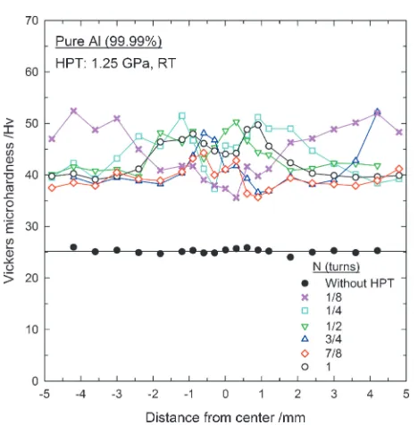
The values of the Vickers microhardness across the diameter of each disk are plotted against the distance from the center in Fig. 1 where the lower solid points correspond to the as-received and unprocessed condition and the remaining points denote torsional straining through total numbers of turns, N, from 1/8 to 1 whole revolution. It is apparent that the hardness increases significantly at the onset of straining. Specifically, after one eighth turn of HPT the hardness increases by a factor which is slightly lower than 2 where this increase is comparable to the increase in strength typically recorded in a range of commercial aluminum-based alloys after processing through 1 pass in ECAP.24)
A critical and important feature afterN¼1=8in Fig. 1 is that, similar to the results reported for several different materials,4–13,15,16,25,26)the measured hardness in the center of the disk is lower than in the surrounding areas. However, this result differs from earlier measurements on aluminum of 99.99% purity where the measured hardness was consistently higher in the centers of the disks after small numbers of whole revolutions.14,17,26)Thus, these measurements provide a direct demonstration of the importance of recording the values of hardness after fractional numbers of turns in order to obtain a complete understanding of the microstructural evolution occurring during processing by HPT.
1/2 turn is needed with high-purity Al in order to attain the conventional result of an increased hardness at the center and lower values of hardness around the edge.
All of the microhardness measurements taken from the rectilinear grid patterns, with incremental spacings of 0.3 mm, were plotted in the form of color-coded contour maps to provide pictorial images of the distributions of the individual hardness values over the disk surfaces. These plots are shown in Fig. 2 for disks torsionally strained through 1/8, 1/4, 1/2, 3/4 and 7/8 turns where the X and Y axes denote two arbitrarily-selected orthogonal axes marked in mm such that the central position is at (0,0). All measurements ofHv are shown within incremental values ofHv¼5with a total range inHvfrom 30 to 60 and with the scale shown as the inset at the lower right. An earlier report presented similar color-coded representations for the same material processed by HPT at a pressure of 1.25 GPa when torsionally strained through 1, 3 and 5 turns.14)
In the earlier report it was shown that the disks become reasonably homogeneous in hardness values when strained to N¼5turns with a hardness of40whereas afterN¼1turn the hardness in the central region is higher than around the edge of the disk by Hv10. The present results are consistent with these general trends for all measurements taken at and above N¼1=4 turn. However, in the earliest stages of processing, at N ¼1=8 turn, the situation is reversed and the highest hardness values occur around the edge. It is also apparent from Fig. 2 that the total extent of the region of higher hardness decreases with increasing amounts of torsional straining.
3.2 Microstructural evaluation after HPT
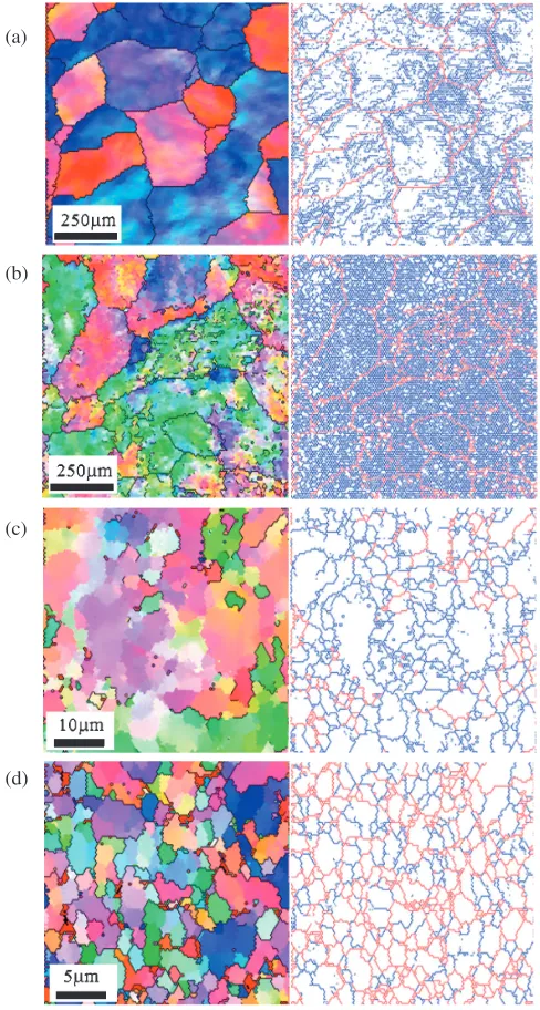
Detailed microstructural observations were undertaken and representative examples obtained by EBSD are shown in Fig. 3 where the upper line corresponds toN¼1=8turn in
the center of the disk, the second line corresponds toN¼1=8 turn at the edge of the disk, the third line corresponds to N¼1=4 turn at the edge of the disk and the bottom line corresponds toN¼1turn at the edge of the disk: the images in the left column depict the grain configurations and the relative orientations of the individual grains and the images in the right column show the individual grain boundaries within each area where the high-angle boundaries having misorientations 15 are marked in red and the low-angle boundaries having misorientations from 2to 15are marked in blue. The grain size is defined for the area surrounded by the former red lines and the subgrain size by the latter blue lines as in the conventional definitions. It should be noted also that the magnifications increase with increasing frac-tional turns because of the gradual development of an ultrafine-grained structure.
(a) (b)
(c)
(e)
(d)
Fig. 2 Color-coded contour maps showing the Vickers microhardness across the surface of disks processed by HPT using an applied pressure of 1.25 GPa and processing through (a) 1/8, (b) 1/4; (c) 1/2; (d) 3/4 and (e) 7/8 turns: the significance of the colors is shown in the inset at lower right. Fig. 1 Average value of the Vickers microhardness,Hv, plotted against the
[image:3.595.53.287.65.303.2] [image:3.595.309.549.71.532.2]Inspection of Fig. 3(a) shows there is only a relatively small change in the microstructure in the central region of the disk after 1/8 turn. The grain size was measured as 250mm but subgrains with low-angle boundaries have formed within these larger grains. However, there is a large average spacing between the subgrain boundaries. It should be noted that the presence of these subgrain boundaries and/or the presence of dislocations within the grains leads to the gradual changes in color or color gradients which are clearly visible in the EBSD image. The grain size was also250mmatN¼1=8turn near the edge of the disk as shown in Fig. 3(b) and again there are subgrains formed with the larger grains. However, in this condition the subgrains were relatively densely developed and the average spacing between the low-angle boundaries was very small.
Close inspection shows there is also some evidence at this early stage of processing for a gradual evolution into high-angle boundaries. An earlier investigation using trans-mission electron microscopy showed the dislocation density was very high within the subgrains at this early stage of processing.27)
Figures 3(c) and (d) show the edges of the disks after straining through 1/4 and 1 turn, respectively. After 1/4 turn in Fig. 3(c) the grain size is reduced to5mm, the subgrains are well developed and the fraction of grains having high-angle boundaries has increased. In this condition the micro-structure is heterogeneous with some regions having sub-grains and a high density of dislocations and other regions having ultrafine grains with relatively few dislocations. Finally, the situation afterN¼1turn is shown in Fig. 3(d) where the grain size is 2mm and there are very few subgrains but there is a large fraction of grains having high-angle grain boundaries. For this condition there is no measurable difference between the sizes of the grains and the subgrains, thereby confirming the ultfrafine-grained micro-structures produced in HPT are due to an evolution in the boundaries from predominantly low-angle misorientations to predominantly high-angle misorientations. This is consistent with recent results for aluminum of the same purity processed by equal-channel angular pressing (ECAP) where the fractions of high-angle boundaries were recorded up to 12 separate passes through the ECAP die.28)In this condition the dislocation density within the individual grains is relatively low27)which leads to the measured decrease in hardness by comparison with the initial stages of HPT.
4. Discussion
The present results provide a very useful addition to the data presented earlier showing the variations of hardness in high-purity Al processed by HPT through 1, 3 and 5 turns under an applied pressure of 1.25 GPa.14)The experimental data presented in Figs. 1 and 2 give additional information for samples of the same material processed through fractional (a)
(b)
(c)
(d)
Fig. 3 Images obtained by EBSD for disks processed by HPT where (a) shows 1/8 turn near the center, (b) shows 1/8 turn near the edge; (c) shows 1/4 turn near the edge and (d) shows 1 turn near the edge: the relevant boundary patterns are shown in the right column with red and blue lines used to identify high-angle and low-angle boundaries, respectively.
[image:4.595.310.541.71.259.2] [image:4.595.46.290.72.528.2]numbers of whole turns and this is supplemented by the comprehensive microstructural information obtained by EBSD and shown in Fig. 3.
At first sight, the experimental datum points shown in Fig. 1 appear to scatter randomly with no clear and consistent variation with increasing number of turns and therefore with increasing amounts of applied strain. However, there is a critical difference between processing in ECAP and HPT because in ECAP the strain remains constant throughout the billet whereas in HPT the strain varies across the disk as represented by eq. (1). This means in practice that, although it is meaningful to plot the values of the Vickers microhard-ness directly against the number of imposed passes in processing by ECAP,29) it is not possible to construct a similar simple plot for samples processed by HPT because of the continuous variations in strain within each sample. This problem was first recognized in very early work where HPT was applied to ring samples and this led to the introduction of the equivalent strain.30)In a comprehensive more recent study of the processing of an austenitic steel by HPT, it was shown that a plot of the individual values of the microhardness against equivalent strain gave a unique plot with all datum points falling on or about a single line and with similar results also for copper and chromium.13) More recently this same approach was used to interpret hardness data obtained in the processing by HPT of both disk and ring samples.27,31–35)
In order to make use of this analytical approach in the present investigation, it is first noted that the thicknesses of the HPT disks are reduced in HPT processing and this reduction generally increases with increasing numbers of turns.25) In this investigation, the sample had an initial thickness of0:85mm and this was reduced to0:80mm on application of the applied pressure and it was further reduced to 0:76mm after one turn of HPT. Since the thickness reductions for different fractional revolutions are all within 5% of these values, a thickness ofh¼0:8mm was used to estimate the equivalent strain using eq. (1). The results of these calculations are shown in Fig. 4 where all of the datum points from Fig. 1 are replotted as a function of the estimated equivalent strain.
It is apparent from Fig. 4 that the datum points for different fractional revolutions and for different positions on the HPT disks all tend to lie around a single line showing a peak at an equivalent strain of2:0and at higher strains, above7, the hardness values attain a steady-state value which remains essentially constant to even higher strains. This result matches earlier results plotted for aluminum of the same purity where the datum points were extended to strains of >40using ring samples.31,34)The scatter in the points visible in Fig. 4 at equivalent strains in the range of 2{7 is attributed to the inhomogeneous development of the micro-structure when processing thin disks by HPT.
It is also instructive to delineate the EBSD images shown in Fig. 3 in terms of the estimated equivalent strain within the disk at the point used for microstructural examination. For Fig. 3(a), the sample was examined near the center of the disk so that the equivalent strain is probably <0:3 which corresponds to the initial increase in hardness before the maximum. For Fig. 3(b), the equivalent strain near the edge
of the disk is 2 and this corresponds to the hardness maximum. For Fig. 3(c), the equivalent strain near the edge of the disk after 1/4 turn is 4 which correspond to the region where the hardness decreases prior to attaining a steady-state condition. Finally, for Fig. 3(d) the equivalent strain near the edge of the disk after 1 turn is16which is within the steady state region.
Three conclusions may be drawn from Fig. 4. First, hardness values vary directly with the estimated equivalent strain and this variation is directly comparable to the variation in hardness with the imposed strain when process-ing by ECAP because earlier measurements on the same material showed a peak in hardness after 2 ECAP passes which, for an ECAP die with a channel angle of 90, corresponds to an applied strain of 2.36) Second, the hardness increases at small equivalent strains up to 2, decreases thereafter, and reaches a steady-state condition at equivalent strains above 7. These changes are consistent with the very high stacking fault energy in high purity aluminum and the consequent rapid microstructural recovery that was documented in an earlier study.14) Third, the hardness values saturate at equivalent strains above 7 as revealed in this investigation and in experiments with ring samples.31–35)
5. Summary and Conclusions
(1) Samples of high-purity aluminum were processed by high-pressure torsion under a pressure of 1.25 GPa at room temperature. The torsional straining was terminated after fractional numbers of whole revolutions between 1/8 and 7/8 turns. Microhardness measurements were taken on polished surfaces of the disks and the microstructures were examined using electron back-scatter diffraction.
(2) After 1/4 or more fractional revolutions the values of the microhardness are higher in the centers of the disks than at the edges whereas after 1/8 turn the hardness is higher at the edge than in the center of the disk. All hardness measurements scatter around a unique curve when plotted against the equivalent strain, with the hardness initially increasing up to a strain of 2, thereafter decreasing gradually to a strain of 7 and then remaining constant at higher strains.
(3) Microstructural observations demonstrate a gradual evolution of the microstructure with subgrains evolving into an array of ultrafine grains separated by boundaries having high angles of misorientation.
Acknowledgements
REFERENCES
1) R. Z. Valiev, R. K. Islamgaliev and I. V. Alexandrov: Prog. Mater. Sci.
45(2000) 103–189.
2) A. P. Zhilyaev and T. G. Langdon: Prog. Mater. Sci.53(2008) 893– 979.
3) R. Z. Valiev, Yu. V. Ivanisenko, E. F. Rauch and B. Baudelet: Acta Mater.44(1996) 4705–4712.
4) A. P. Zhilyaev, S. Lee, G. V. Nurislamova, R. Z. Valiev and T. G. Langdon: Scr. Mater.44(2001) 2753–2758.
5) A. P. Zhilyaev, G. V. Nurislamova, B. K. Kim, M. D. Baro´, J. A. Szpunar and T. G. Langdon: Acta Mater.51(2003) 753–765. 6) G. Sakai, Z. Horita and T. G. Langdon: Mater. Sci. Eng. A393(2005)
344–351.
7) A. P. Zhilyaev, K. Oh-ishi, T. G. Langdon and T. R. McNelley: Mater. Sci. Eng. A410–411(2005) 277–280.
8) A. P. Zhilyaev, T. R. McNelley and T. G. Langdon: J. Mater. Sci.42
(2007) 1517–1528.
9) H. Jiang, Y. T. Zhu, D. P. Butt, I. V. Alexandrov and T. C. Lowe: Mater. Sci. Eng. A290(2000) 128–138.
10) Z. Horita and T. G. Langdon: Mater. Sci. Eng. A410–411(2005) 422– 425.
11) A. P. Zhilyaev, A. A. Gimazov, G. I. Raab and T. G. Langdon: Mater. Sci. Eng. A486(2008) 123–126.
12) Z. Yang and U. Welzel: Mater. Lett.59(2005) 3406–3409. 13) A. Vorhauer and R. Pippan: Scr. Mater.51(2004) 921–925. 14) C. Xu, Z. Horita and T. G. Langdon: Acta Mater.55(2007) 203–212. 15) C. Xu, Z. Horita and T. G. Langdon: Acta Mater.56(2008) 5168–
5176.
16) L. Balogh, T. Unga´r, Y. Zhao, Y. T. Zhu, Z. Horita, C. Xu and T. G. Langdon: Acta Mater.56(2008) 809–820.
17) M. Kawasaki and T. G. Langdon: Mater. Sci. Eng. A 498 (2008) 341–348.
18) Y. Todaka, M. Umemoto, A. Yamazaki, J. Sasaki and K. Tsuchiya: Mater. Trans.49(2008) 7–14.
19) D. Orlov, P. P. Bhattacharjee, Y. Todaka, M. Umemoto and N. Tsuji: Scr. Mater.60(2009) 893–896.
20) D. Orlov, Y. Todaka, M. Umemoto and N. Tsuji: Mater. Sci. Eng. A
499(2009) 427–423.
21) Y. Todaka, M. Umemoto, A. Yamazaki, J. Sasaki and K. Tsuchiya: Mater. Trans.49(2008) 47–53.
22) K. Edalati, Z. Horita and T. G. Langdon: Scr. Mater.60(2009) 9–12. 23) F. J. Humphreys: Scr. Mater.51(2004) 771–776.
24) Z. Horita, T. Fujinami, M. Nemoto and T. G. Langdon: Metall. Mater. Trans.31A(2000) 691–701.
25) C. Xu, Z. Horita and T. G. Langdon: J. Mater. Sci.43(2008) 7286– 7292.
26) C. Xu and T. G. Langdon: Mater. Sci. Eng. A503(2009) 71–74. 27) Y. Ito and Z. Horita: Mater. Sci. Eng. A503(2009) 32–36. 28) M. Kawasaki, Z. Horita and T. G. Langdon: Mater. Sci. Eng. A524
(2009) 143.
29) Z. Horita, K. Kishikawa, K. Kimura, K. Tatsumi and T. G. Langdon: Mater. Sci. Forum558–559(2007) 1273–1278.
30) I. Saunders and J. Nutting: Metal Sci.18(1984) 571–575. 31) Y. Harai, Y. Ito and Z. Horita: Scr. Mater.58(2008) 469–472. 32) K. Edalati, T. Fujioka and Z. Horita: Mater. Sci. Eng. A497(2008)
168–173.
33) Y. Harai, K. Edalati, Z. Horita and T. G. Langdon: Acta Mater.57
(2009) 1147–1153.
34) K. Edalati and Z. Horita: Mater. Trans.50(2009) 92–95.
35) K. Edalati, T. Fujioka and Z. Horita: Mater. Trans.50(2009) 44–50. 36) Y. Iwahashi, J. Wang, Z. Horita, M. Nemoto and T. G. Langdon: Scr.