http://dx.doi.org/10.4236/jsip.2013.41007 Published Online February 2013 (http://www.scirp.org/journal/jsip)
Enhancement of Error-Correction Coding of Spatial
Watermarks in Gray Code
Tadahiko Kimoto
Faculty of Science and Engineering, Toyo University, Kawagoe, Japan. Email: [email protected]
Received October 21st, 2012; revised November 24th, 2012; accepted December 8th, 2012
ABSTRACT
This paper demonstrates how channel coding can improve the robustness of spatial image watermarks against signal distortion caused by lossy data compression such as the JPEG scheme by taking advantage of the properties of Gray code. Two error-correction coding (ECC) schemes are used here: One scheme, referred to as the vertical ECC (VECC), is to encode information bits in a pixel by error-correction coding where the Gray code is used to improve the perform-ance. The other scheme, referred to as the horizontal ECC (HECC), is to encode information bits in an image plane. In watermarking, HECC generates a codeword representing watermark bits, and each bit of the codeword is encoded by VECC. Simple single-error-correcting block codes are used in VECC and HECC. Several experiments of these schemes were conducted on test images. The result demonstrates that the error-correcting performance of HECC just depends on that of VECC, and accordingly, HECC enhances the capability of VECC. Consequently, HECC with appropriate codes can achieve stronger robustness to JPEG—caused distortions than non-channel-coding watermarking schemes.
Keywords: Error-Correction Coding; Gray Code; Digital Watermark; Spatial Domain; JPEG DCT Compression
1. Introduction
Digital watermarking is a technique for combining digital signals with additional data, which are commonly called watermarks, so as to make the resultant signal changes imperceptible [1]. For image signals, a watermark is em-bedded there, and from the watermarked image the wa-termark is to be recovered afterward.
When the watermarked image is transmitted through image communication systems, the image is usually com-pressed by, for example, the JPEG coding scheme, and then transmitted to a communication channel. Hence, when it is received, the image is usually distorted due to the lossy data compression. Because the data compres-sion is an ordinary processing in communication systems, if the watermarking is carried out before transmission, the watermark must be robust against distortions caused by at least the data compression scheme in use.
Spatial-domain watermarks, which are a kind of wa-termarks to be embedded into a spatial signal domain, that is, into raw signals, have generally weak robustness to subsequent signal distortions because even a small change in a signal value causes significant changes in the whole bit sequence. However, they are nevertheless used in a number of applications such as steganography and fragile watermarking for content authentication.
Error correction techniques of channel coding such as
the BCH (Bose-Chaudhuri-Hockquenghem) codes can be used to improve the robustness of spatial-domain water- marks [2]. A number of the related coding methods were studied in the late 1990’s [3]. Most of the error-correc- tion coding (ECC) methods have been applied to trans- form-domain watermarks, for instance, in [4].
It has been reported in [5] that the error-correction coding in Gray codewords is more effective than that in natural binary codewords for JPEG-DCT compression. In the method, a watermark bit is encoded with an error- correcting block code, and the generated codeword is embedded in the bit sequence of a pixel that is expressed in Gray code. Thus, a watermark bit is embedded in each pixel with a protection from the change in pixel level. We here refer to this method as the vertical error-correc- tion coding (VECC), meaning the coding in the vertical direction of the pile of image bit-planes.
watermarking and JPEG coding, we demonstrate how effectively the HECC can actually perform to improve the robustness of spatial watermarks for the JPEG lossy compression. To simplify the evaluation of the coding performance, simple one of error-correcting block codes is used in the HECC.
The rest of this paper is organized as follows: In Sec-tion 2, the properties of the Gray code, which play an essential role in the proposed scheme, is explained. In Section 3, the schemes for watermarking spatial image signals by error-correction coding are described; first, the VECC based on [5] is described, and then, the HECC is specified. In Section 4, the performance of HECC is evaluated from the results of some experiments conducted on test images of natural scenery. The degree of robust-ness that the scheme achieves against JPEG-DCT com-pression is discussed in comparison with that a typical one of non-channel-coding watermarking schemes per-forms. Section 5 concludes the paper.
2. Properties of Gray Code
2.1. Difference between Adjacent Codewords As regards the properties of Gray codes, it is well known the fact that any two adjacent codewords differ in only one bit-position. The bit-position is definitely given as follows: Let CG denote the m-bit Gray code and CG(v) be the codeword in CG associated with a signal level v, where 0 v 2m1. The bit-position, h, where C vG
and C vG
1
differ is given by
0, if is even
max 1 2 ,i if is odd
v
i v v
, (1)
where the bit-position 0 indicates the least significant bit (LSB). In addition, we find out that 1 if v is odd.
2.2. Difference between Two Codewords
As for d2 , the difference between C vG
and
G is given by the result of accumulating bit changes from
C vd
G
C v through C v dG
. Hence, these two codewords differ in those bit positions where the bit inversion occurs once or odd times during the accumula-tion. Thus, one or more bits differ between the code-words, and the difference bit-positions are determined from the starting level v. Consequently, the distribution of the difference bits in m bits for all the possible v’sis derived using Equation (1).
0 v 2m
1
d
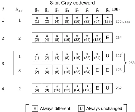
Letting m = 8 as a practical example, Figure 1 illus-trates the distributions of the difference bits in 8-bit Gray codewords,
g7g g1 0 , for each value of d from 1 to 4,E E E E U U * (128) * (64) * (32) * (16) * (8) * (4) * (128) * (64) * (32) * (16) * (8) * (4) * (2) * (64) * (32) * (16) * (8) * (4) * (2) * (64) * (32) * (16) * (8) * (4) * (2) * (1) 252 254 253 127 126
Always different Always unchanged
[image:2.595.308.536.85.274.2]E U 2 3 4 2 1 3 2
Figure 1. Distributions of difference bits between two 8-bit Gray codewords apart by a difference signal-level d from each other, for d = 1, 2, 3 and 4: Ndiff denotes the number of difference bits occurring in a codeword; the number writ-ten in each bit position in parentheses denotes the number of codeword pairs which differ there; the asterisks indicate those bit-positions only one of which differs at the same time.
for instance. As an example, for d = 1, out of 255 possi-ble codeword pairs, 128 pairs differ in the bit-position g0,
64 pairs in g1, 32 pairs in g2, 16 pairs in g3, 8 pairs in g4,
4 pairs in g5, 2 pairs in g6, and one pair in g7. Thus, for a
given difference signal-level d, with regard to pairs of two codewords whose levels are apart by d from each other, the number of bit positions where the two Gray codewords differ lies in a narrower range than the num-ber of bit positions where the two natural binary code-words differ.
3. Error-Correction Coding Scheme
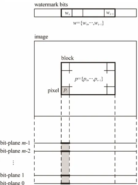
Figure 2 shows the data structure in the horizontal and vertical error-correction coding schemes. Figure 3 illus-trates a diagram of the HECC scheme involving VECC scheme in the use of the data structure. In the following, first, the VECC scheme is developed, and then, the HECC scheme is explained.
3.1. Vertical Error-Correction Coding
Taking advantage of the above properties of Gray codes, error-correcting codes can correct difference bits caused in Gray codewords by level changes more effectively than those caused in natural binary codewords. In the VECC scheme, one watermark bit is to be embedded into the bit pattern of one pixel by the error-correcting in Gray codes: Suppose that signal levels are expressed in
Figure 2. Data structure used in horizontal and vertical error-correction coding in image watermarking.
single-error-correcting (SEC) codeword, where gl is the
lth bit of the Gray codeword for , and
g0indicates the LSB. The scheme with the above l value
is referred to as ECCGl, . An information bit of the (3, 1) SEC code corresponds to a watermark bit. Note that the (3, 1) code is the simplestone of the (n, k) code depicted in Figure 3.
0,1, , 1
l m
0,1,
l
In embedding a watermark bit into a pixel, the natural binary codeword representing the source level is first converted to a Gray codeword. Either one of the two SEC codewords that is associated with the watermark bit is chosen and put in the Gray codeword. The resulting Gray codeword is, then, converted back to a natural bi-nary codeword. As a result, the difference in signal level between the source and encoded natural binary code-words leads to a spatial distortion. We refer to such a distortion caused by the embedding of watermarks as an embedding distortion.
In a (3, 1, 3) code, there exist the following four kinds of pair of 3-bit codewords that are apart from each other by the Hamming distance of 3: 1) {(000), (111)}; 2) {(001), (110)}; 3) {(011), (100)}; and 4) {(010), (101)}. On the assumptions both that each m-bit level is equally likely to occur at any signal and that a watermark bit is a random variable, the amount of embedding distortions was estimated by an expected value of mean square er-
Figure 3. Diagram of HECC scheme where HECC uses a linear block code, VECC involves ECCG0.
rors (MSEs) between codewords. As a result, for ECCG0,
the codeword pair 4), denoted by CEG, that yields the smallest distortion has been selected. CEG also applies to ECCG1 to minimize embedding distortions.
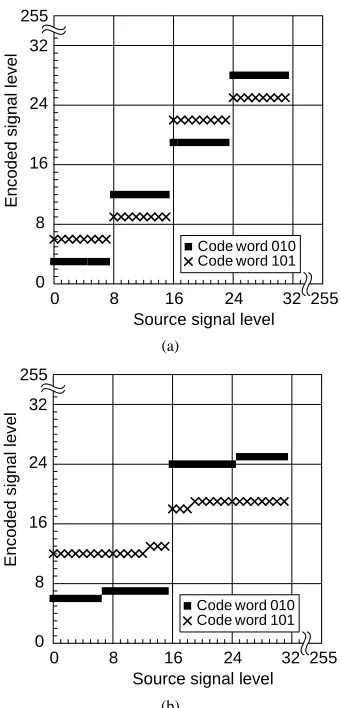
Now that CEG is given, two encoded levels corre-sponding to respective watermark bit-values of 0 and 1 are determined for each source level. Figures 4(a) and (b) show the relationship between source levels and encoded levels in ECCG0 and ECCG1, respectively. The
relation-ship repeats periodically over the 8-bit dynamic range every 16 levels in ECCG0, every 32 levels in ECCG1.
ECCG with > 1 is no longer practical for 8-bit signals due to large embedding distortions.
[image:3.595.60.285.83.384.2]Code word 010 Code word 101
0 8 16 24 32 255
0 8 16 24
Source signal level
Enco
ded
si
gn
al
leve
(a)
Code word 010 Code word 101
0 8 16 24 32 255
0 8 16 24 32 255
Source signal level
Encoded
si
gnal
le
v
el
[image:4.595.87.257.82.436.2](b)
Figure 4. Source-encoded level relationship of ECC meth-ods using 8-bit Gray codewords: (a) ECCG0; (b) ECCG1.
CEG codewords. As reported in [5], ECCG1 possesses a
larger RP for level changes than ECCG0. At the same time,
however, the embedding distortion caused by ECCG1 gets
so large that it tends to get perceptible and similar to
falsecontours [6] particularly in smooth image areas.
3.2. Horizontal Error-Correction Coding
To improve the robustness of the embedded watermarks to level changes, another error-correction coding is ap-plied to pixel blocks where the ECCG0 scheme is applied
to each pixel to encode each bit of the error-correcting codeword. Suppose that codewords in a (n, k) t-error- correcting code are to be embedded into blocks of n pix-els. Here, k information bits of the code correspond to watermark bits. Roughly speaking, if the ratio
n t n
is larger than the pixel correct probability RP, this code is expected to work effectively.On the basis of the result of a preliminary experiment regarding the properties of RP, the values of RP above 1/2 are supposed. Accordingly, a (3, 1) SEC code is used for the coding scheme here, namely, n = 3 and k = 1. Also,
We refer to this horizontal error-correction coding scheme involving ECCG0 as HECCG0.
4. Experiment and Results
4.1. Experimental Method
1) Implementation of watermarking: Experiments of the watermarking schemes were conducted in the fol-lowing way: four 8-bit monochrome images of 256 by 256 pixels, Lena, Aerial, Peppers, and Parrots, which are commonly used in image research, were used as source images. The watermark bits were generated by a pseudo- random number generator with a computer. The whole of each source image was divided to row-wise 3-pixel blocks to implement HECCG0, excluding the residual pixels at
the right end of the image.
Here, we define a watermarking rate by the ratio of the number of watermark bits to the number of pixels carry-ing them, denoted by τ (bits/pixel), which is similar to the code rate in channel coding. We also define an embed-ding ratio, denoted by ρ, by the proportion of pixels se-lected to use in the whole source image. Suppose that a given source image consists of N pixels, then, the number of watermark bits embedded in the image is given by
N
. HECCG0 was performed with τ = 1/3 (bits/pixel)
and 1 in the experiment. Note that the watermark-ing is actually to be implemented with 1 so as to conceal the locations where watermarks are embedded in the image.
2) Implementation of JPEG coding: Each watermarked image was encoded by the JPEG DCT-baseline coding scheme, and then, the resulting data were decoded to reconstruct the image. To obtain various amount of cod-ing distortion, the JPEG codcod-ing performance was varied by modifying the luminance-quantization matrix that is specified as the recommended one in [7].
From the reconstructed image, first, the vertical (3, 1)-SEC codeword at each pixel is decoded. Then, the horizontal (3, 1)-SEC codeword at each pixel-block is decoded. Here, we define a block correct ratio, RB, by the proportion of correctly recovered ones of horizontal SEC codewords. The block correct ratio can be regarded as the watermark recovery ratio of HECCG0, denoted by RW, which is defined by the proportion of correctly recovered ones of embedded watermark bits.
3) Pixel surrounding method: As in [5], the pixel sur-rounding method (PSM) [8] was used for the perform-ance comparison with the error-correcting watermarking schemes. The procedures and properties of PSM are out-lined below.
a cover image f, the mean value, a, of the eight pixels surrounding x in the 3 × 3 neighborhood is calculated, and then, letting denote a signal level of the pixel x, is replaced with the value
f x
f x if w0, or
otherwise, where δ is a specified level. Conse-quently, the source image is not only low-pass filtered but also subjected to signal variation of δas a result. The locations of selected pixels are to be kept secret.
To extract watermark bits from a given image f, at the pixel x' of f corresponding to the selected x of f, the mean value, , of the eight pixels surrounding x' is calculated, and then the watermark bit w' is determined as 0 if f
x , or 1 otherwise. Thus, the water-marking rate τof PSM is 1 (bit/pixel) in this experiment.Suppose that the embedding at each selected pixel is carried out independently in the source image. If two of the selected pixels are adjacent in the 3 × 3 neighborhood, the watermark bits extracted from these pixels are likely to be wrong due to unexpected differences between the mean value calculated before watermarking and that cal-culated after watermarking. Thus, the watermarked im-age is likely to be already somewhat corrupted without subsequent distortions, particularly in the case of large ρ over 1/9.
4.2. Experimental Results
1) Embedding distortions: The amount of embedding distortions was estimated by the mean square error (MSE) between the entire source and the entire watermarked image. Here, the PSM was implemented for each source image with the embedding ratio 1 3 for comparison with HECCG0 under the condition of embedding the same
number of watermark bits.
Table 1 lists the MSEs of the watermarked images generated by HECCG0 and by PSM with various
embed-ding depth δs for the four test images, in terms of peak- signal-to-noise ratios (PSNRs) in decibel (dB). The amount of embedding distortions caused by HECCG0 is much less
than those caused by PSM, by more than 6 dB of PSNR. Although another experimental result shows that, com-pared with PSM with 1, the distortion caused by PSM with 1 3 is reduced by an increase of about 5 dB in PSNR, the distortion tends to increase with the parameter δ as shown in Table 1.
Weighted signal-to-noise ratios (WSNRs) of the wa-termarked images are also listed in Table 1. These values were measured under the condition of both the viewing distance of 13 inches and the displaying pixel-density of 200 pixels/inch. Any watermarked image of HECCG0
shows the WSNR over 42 dB, still about 6 dB larger than the watermarked images of PSM.
Table 1 also includes the watermark recovery ratios. As mentioned before, some of the embedded watermark
Table 1. Watermarking results of test images.
Method Measure Lena Aerial Peppers Parrots
HECCG0 PSNRa 38.8 38.8 38.8 38.8
WSNRa 42.5 42.6 42.4 42.2
RWb 1 1 1 1
PSM PSNR 32.4 30.1 33.4 32.4
(δ= 1) WSNR 36.0 33.3 36.7 35.8
RW 0.82 0.70 0.87 0.90
PSM PSNR 32.3 30.1 33.3 32.3
(δ= 2) WSNR 35.9 33.3 36.5 35.6
RW 0.91 0.81 0.93 0.95
PSM PSNR 32.1 30.0 33.1 32.1
(δ= 3) WSNR 35.7 33.2 36.3 35.5
RW 0.95 0.88 0.96 0.97
PSM PSNR 31.5 29.6 32.4 31.6
(δ= 5) WSNR 35.2 32.9 35.7 35.0
RW 0.98 0.95 0.98 0.98
a
PSNR (dB) and WSNR (dB): embedding distortions; bRW: watermark
re-covery ratio.
bits are likely to be already lost in the PSM-watermarked images. To increase the recovery ratio, it is necessary to increase the parameter δ.
To observe image appearance, examples of the water-marked images are shown in Figure 5. HECCG0 hardly
yields perceptible distortions over the resulting images as shown in Figure 5(b). As seen in Figure 5(c), on the contrary, PSM makes the watermarked image look blurred and corrupted. Such degradation looks prominent in Figure 5(c’) where the image consists of a lot of small objects.
2) Effects of horizontal SEC coding: Both the pixel correct probabilities RP and the block correct ratios RB were measured from a set of the watermarked images of the four test images that had been distorted by JPEG compression in various degrees. As shown in Figure 6, the correlation between them agrees well with the theo-retical relation, that is, RBRP2
3 2 RP
. This ex-perimental result indicates that HECCG0 is as effective asexpected according to the bit rate given by VECC for actual images such as those of natural scenery.
3) Robustness for JPEG-distortions: Figure 7 shows the robustness of each watermarking scheme to distor-tions caused by JPEG coding for the four test images, with the watermark recovery ratios plotted against the amount of distortions measured in PSNR. For any of these test images, HECCG0 shows a definite improvement
in the robustness over the ECCG0 while the watermark
recovery ratio is still lower than that of ECCG1. Although
the robustness performance of HECCG0 is nearly
(a) (a’)
(b) (b’)
[image:6.595.77.521.85.413.2](c) (c’)
Figure 5. Examples of watermarked images: zoomed original image (a) Lena and (a’) Aerial of 128 by 128 pixels; (b) and (b’) results of ECCG0; (c) and (c’) results of PSM with ρ = 1/3 and δ = 3. Each right figure shows a closer view of a 32 by 32 pixel portion of the left figure.
initial degradation as listed in Table 1, which is observed particularly in Figure 7(b).
0 0.2 0.4 0.6 0.8 1 0
0.2 0.4 0.6 0.8 1
Pixel correct probabilityRp
Bl
oc
k
c
or
re
c
t
ra
ti
o
RB
5. Conclusion
The code that has been used in HECC in the experiment is a (3, 1) single-error-correcting code. For this code, the actual performance with respect to error-correction for the test images of natural scenery under the condition of being distorted by JPEG DCT-baseline scheme was meas-ured. With respect to the performance of VECC, it has been observed from the experimental result that those pixels which result in the extraction of wrong bits are distributed almost uniformly in the whole JPEG-distorted image. This fact shows the evidence that the error-cor- recting code of HECC performs according to the pixel correct probabilities of VECC. Thereby, HECC enhances the capability of VECC to recover watermark bits from distorted images, and accordingly, achieves stronger ro-bustness to JPEG-distortions particularly for high-quality images than the non-channel-coding and filter-based PSM. According to the above conclusion, we can consider the use of sophisticated codes in HECC, such as BCH codes, Figure 6. Correlation between pixel correct probabilities
and block correct ratios: total 80 measurements obtained from four test images are plotted. The curve shows the theoretically expected values.
[image:6.595.93.251.462.615.2]20 30 40 50 60 Image quality PSNR (dB)
1.0
0.8
0.6
0.4
0.2
0.0
W
a
te
rm
ar
k
rec
o
v
e
ry
ra
tio
RW
3
20 30 40 50 60
Image quality PSNR (dB) 1.0
0.8
0.6
0.4
0.2
0.0
Wa
te
rma
rk
recove
ry
rat
io
RW
ECCG0
HECCG0
ECCG0
HECCG0
ECCG1 ECCG1
PSM PSM
Image Lena
3
PSM PSM
Image Aerial
(a) (b)
20 30 40 50 60
Image quality PSNR (dB) 1.0
0.8
0.6
0.4
0.2
0.0
W
a
te
rma
rk
re
c
ov
ery
rat
io
RW
3
20 30 40 50 60
Image quality PSNR (dB) 1.0
0.8
0.6
0.4
0.2
0.0
W
a
terma
rk
re
covery
ratio
RW ECCG0
HECCG0 ECCG0
HECCG0 ECCG1
PSM PSM
Image Peppers
ECCG1
3
PSM PSM
Image Parrots
[image:7.595.87.513.82.399.2](c) (d)
Figure 7. Robustness of the watermarked images (a) Lena; (b) Aerial; (c) Peppers and (d) Parrots against distortions caused by JPEG lossy compression: all the PSMs are implemented with ρ= 1/3.
Trellis codes, low-density parity-check (LDPC) codes, Turbo codes or even the most advanced error-correcting codes currently known, namely, iteratively decoding codes to approach the ultimate limits of coding [9].
REFERENCES
[1] B. M. Macq, “Special Issue on Identification and Protec- tion of Multimedia Information,” ProceedingoftheIEEE, Vol. 87, No. 7, 1999, pp. 1059-1276.
[2] J. R. Hernández, F. P. González and J. M. Rodriguez, “The Impact of Channel Coding on the Performance of Spatial Watermarking for Copyright Protection,” Pro-
ceedingsofthe 1997 IEEE InternationalConference on
Acoustics, Speech, andSignalProcessing, Seattle Wash- ington, 12-15 May 1998, pp. 2973-2976.
[3] I. J. Cox, M. L. Miller and J. A. Bloom, “Digital Water- marking,” Morgan Kaufmann Publishers, San Francisco, 2002.
[4] Y. Yi, M. H. Lee, J. H. Kim and G. Y. Hwang, “Robust Wavelet-Based Information Hiding through Low-Density
Parity-Check (LDPC) Codes,” In: T. Kalker, I. J. Cox and Y. M. Ro, Eds., Digital Watermarking, Springer-Verlag, Berlin, 2004, pp. 117-128.
doi:10.1007/978-3-540-24624-4_9
[5] T. Kimoto, “Error-Correction Coding of Spatial Image Watermarks in Gray Code,” Proceedingofthe 7thInter- national Conference on Signal-Image Technology and Internet-BasedSystems, Dijon, 28 November-1 December 2011, pp. 358-365. doi:10.1109/SITIS.2011.51
[6] R. C. Gonzalez and R. E. Woods, “Digital Image Proc- essing,” Addison-Wesley, Boston, 1993.
[7] ISO CD 10918, “Digital Compression and Coding of Con- tinuous-Tone Still Images,” ISO/IEC JTC1/SC2/WG10, 1991.
[8] F. H. Wang, J. S. Pan and L. C. Jain, “Innovations in Digital Watermarking Techniques,” Springer-Verlag, Ber- lin, 2009. doi:10.1007/978-3-642-03187-8
[9] M. H. M. Costa, “Writing on Dirty Paper,” IEEETrans-