ISSN (Print) : 2320 – 3765
ISSN (Online): 2278 – 8875
I
nternational
J
ournal of
A
dvanced
R
esearch in
E
lectrical,
E
lectronics and
I
nstrumentation
E
ngineering
(A High Impact Factor, Monthly, Peer Reviewed Journal)
Website: www.ijareeie.com
Vol. 8, Issue 3, March 2019
Perturb & Observe MPPT Technique used for
Standalone Photo Voltaic System
Arti Pandey1, Sumati Srivastava2
PG Student [Power System], Dept. of EEE, Maharishi University of Information Technology, Lucknow, U.P., India 1
Assistant Professor, Dept. of EEE, Maharishi University of Information Technology, Lucknow, U.P., India 2
ABSTRACT: Solar photovoltaic technology has been used by various global PV markets with 227 GW increasing globally installed PV capacities in 2015 replacing the non-renewable energy resources. The requirement of renewable energy sources is on the rise because of the severe energy crisis in the world today. Solar energy is a vibrant resource in a tropical country like ours. The main difficulty for the penetration and reach of solar PV systems is their low efficiency and high capital cost. To maximize a photovoltaic (PV) system's output power, continuously tracking the maximum power point (MPP) of the system is necessary. This paper proposes a solar tracker and modified Perturb and Observe (P&O) algorithm for the standalone solar photo-voltaic system. Proposed algorithm limits the search space of the power curve to 10% area that contains Maximum Power Point (MPP) and starts perturbation and observation within that limited search space. The proposed P&O algorithm was simulated in MATLAB/Simulink.
KEYWORDS: MPPT, photovoltaic, power electronics, Perturb & Observe.
I.INTRODUCTION
Non-conventional energy is the energy which comes from natural resources such as sunlight, wind, rain, tides and geothermal heat. These resources of energy are renewable and can be naturally restocked. Therefore, for all practical purposes, these resources can be considered to be unlimited, unlike deteriorating conventional fossil fuels. Apart from the quickly decreasing reserves of fossil fuels in the world, another main factor working against fossil fuels is the pollution associated with their combustion. Contrastingly, non-conventional energy resources are known to be cleaner and produce more energy without the dangerous effects of pollution unlike their non-renewable equivalents.
Solar energy can be used in two major ways .Firstly; the absorbed heat can be utilized as solar thermal energy, with applications in space heating. Another substitute is the conversion of incident solar radiation to electrical energy, which is the most usable form of energy. This can be attained with the help of solar photovoltaic cells or with concentrating solar power plants.
Solar photovoltaic has been subjected to efficiency upgrading since the invention of the photovoltaic cell. Once the photovoltaic cell is made in the laboratory, its efficiency improvement measures cannot be taken. However solar trackers and Maximum Power Point Trackers (MPPT) are used to getting the maximum out of the solar modules what they can provide. As the sun moves through the sky from east to west, solar radiations accomplished by the solar panel and the PV cell starts operating below its maximum power. Likewise, at higher temperatures performance of the solar module is degraded by varying insulation changes in all the parameters of the solar cell shown in characteristics curves of the PV cell in Fig. 1.
ISSN (Print) : 2320 – 3765
ISSN (Online): 2278 – 8875
I
nternational
J
ournal of
A
dvanced
R
esearch in
E
lectrical,
E
lectronics and
I
nstrumentation
E
ngineering
(A High Impact Factor, Monthly, Peer Reviewed Journal)
Website: www.ijareeie.com
Vol. 8, Issue 3, March 2019
Fig. 1: I-V and P-V characteristics of solar PV cell
II.OBJECTIVE
The major objective of this paper proposes a confined search space based P&O algorithm integrated with a solar tracker. Solar tracker makes sure the maximum coupling of the irradiance with the solar panel by keeping the panel always normal to the sun. The proposed algorithm first divides the power curve into three regions: Area 1 and area 3 are the left and right regions to the MPP respectively. Area 2 is the intermediate region of the power curve containing 10% area of the power curve and MPP lies in this area 2. This reduction in the search space reduces the step response time to reach the maximum power and the steady-state oscillations at the maximum power point.
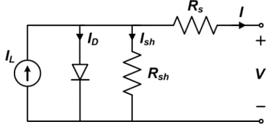
Fig. 2: Standard equivalent circuit of the PV cell
The basic equation that describes the I-V Characteristics of the PV model is given by the following equation
= − ( ) − . +
Cell Current (A)
Light Generated Current (A) Diode Saturation Current
Q
Charge of Electron = 1.6x10⁻¹⁹ (Coul)K
Boltzmann Constant (J/K)V
Cell Output Voltage (V),
Cell Series and Shunt Resistance (Ohms)ISSN (Print) : 2320 – 3765
ISSN (Online): 2278 – 8875
I
nternational
J
ournal of
A
dvanced
R
esearch in
E
lectrical,
E
lectronics and
I
nstrumentation
E
ngineering
(A High Impact Factor, Monthly, Peer Reviewed Journal)
Website: www.ijareeie.com
Vol. 8, Issue 3, March 2019
There are different techniques used to track the maximum power point are:
1) Perturb and observe (hill climbing method) 2) Incremental Conductance method
3) Fractional short circuit current 4) Fractional open circuit voltage 5) Neural networks 6) Fuzzy logic
In this paper we will only discuss about perturb & observe technique.
III.METHODOLOGY (PERTURB-AND-OBSERVE)
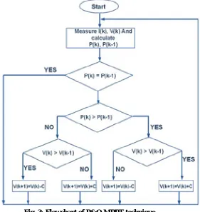
The most commonly used and modest MPPT algorithm is Perturb-and-Observe (P&O) method. Both Hill climbing (HC) and P&O methods have same logic and can be said to be two dissimilar means of visualizing the same method. In HC method duty ratio of the power converter used is perturbed and in P&O method the working voltage of the PV array is perturbed. Since a power converter is generally used with a PV array, so perturbing its duty ratio will automatically perturb the working voltage and thus both the methods are almost same.
The logical flowchart of P&O method is shown in fig.3.
Fig. 3: Flowchart of P&O MPPT technique
ISSN (Print) : 2320 – 3765
ISSN (Online): 2278 – 8875
I
nternational
J
ournal of
A
dvanced
R
esearch in
E
lectrical,
E
lectronics and
I
nstrumentation
E
ngineering
(A High Impact Factor, Monthly, Peer Reviewed Journal)
Website: www.ijareeie.com
Vol. 8, Issue 3, March 2019
speed and almost no oscillation around the MPP can be attained by taking the value of C at kth iteration i.e. C (k) according to following equation.
C (K) = N log10 (abs (ΔP/ΔV))
Fuzzy logic can also be used to select the optimized value of C (k). Both Hill climbing and P&O method can track in the wrong direction, away from the MPP, and may flop under quickly changing atmospheric conditions. To avoid such problem, a solution is proposed in, where a three-point weighted comparison method in which comparison of the actual power point to two earlier ones has been done before taking a decision for the perturbation sign. Generally two sensors are required and the method can be implemented using DSP or microcontroller although analog or digital circuit can also be used.
MPPT Technique Speed Complexity Reliability Implementation
Fractional Voc Medium Low Low Digital/Analog
Incremental Conductance
Varies Medium Medium Digital
Hill Climbing(P & O)
Varies Low Medium Digital/Analog
Fuzzy Logic Fast High Medium Digital
Neural Network Fast High Medium Digital
Table 2: Comparison of common MPPT methods
Fig.4: Basics of MPPT Technique
ISSN (Print) : 2320 – 3765
ISSN (Online): 2278 – 8875
I
nternational
J
ournal of
A
dvanced
R
esearch in
E
lectrical,
E
lectronics and
I
nstrumentation
E
ngineering
(A High Impact Factor, Monthly, Peer Reviewed Journal)
Website: www.ijareeie.com
Vol. 8, Issue 3, March 2019
semiconductors are used in solar cells, provides the electrical field in most solar cells. Semiconductors are a class of materials with conductivity somewhere between metals and insulators. Solar cells are manufactured from monocrystalline materials. Low cost cells are round because they are made from sheets, which are cut from monocrystalline rods as they are pulled from the melt. Joining p and n type material in to a single crystal makes the cross section of a silicon solar cell.
IV.SYSTEM IMPLEMENTATION
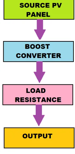
The maximum power point tracking system was initially designed as demonstrates in the figure below. Due to the limitation of any controller which specifies the maximum level of input voltages, the PV panel voltage cannot be input to the controller directly. Sensors (voltage and current) were implemented distinctly for system protection. The figure of full system block diagram is shown in figure 5
Fig.5: Maximum Power Point and DC-DC converter control system diagram.
The programming for the MPPT tracking algorithm was implemented using MPLAB program by connecting the PIC controller “PIC18F46K20” connecting to the PC via the USB port. This controller was used to produce the PWM driving signal to make the DC-DC converter work, the PIC was programmed for producing fixed 50% duty cycle in order for testing the operation of each subsystems already of the signal that it can be generated is approximately 3.3V mentioned in gate driver and sensors.
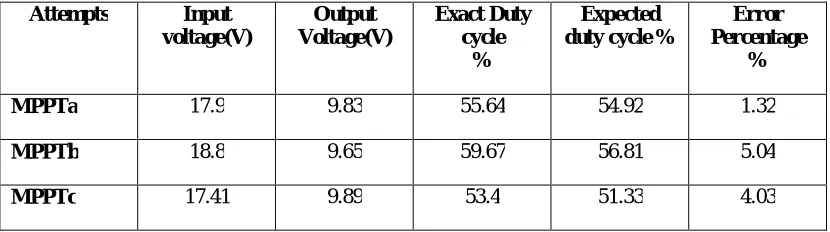
The test was done by running the maximum power point tracking program 3 times (MPPTa, MPPTb and MPPTc) by perturb and observed algorithm, and then took the results of voltage, current, power and duty cycle achieved. The relation between generated duty cycles according to the load is said to be rational with the set input and output voltages. The regulated voltage after several attempts shows better voltage regulation with low level of distortion.
Attempts Input voltage(V)
Output Voltage(V)
Exact Duty cycle
%
Expected duty cycle %
Error Percentage
%
MPPTa 17.9 9.83 55.64 54.92 1.32
MPPTb 18.8 9.65 59.67 56.81 5.04
MPPTc 17.41 9.89 53.4 51.33 4.03
ISSN (Print) : 2320 – 3765
ISSN (Online): 2278 – 8875
I
nternational
J
ournal of
A
dvanced
R
esearch in
E
lectrical,
E
lectronics and
I
nstrumentation
E
ngineering
(A High Impact Factor, Monthly, Peer Reviewed Journal)
Website: www.ijareeie.com
Vol. 8, Issue 3, March 2019
The converter works well with perturb and observed algorithm and capable to generate smooth DC voltage output. Possible further works could be considered the power absorbed and dissipated level for converter which is the prevalent concerns of the system. Mainly at the MOSFET itself, the power efficiency could be enhanced.
V.CONCLUSION
The result of this paper shows that there is basic requirement of MPPT in case of solar tracking. As mentioned above amongst the various techniques of MPPT Perturb and Observe Method (P&O) is best for both digital and analog system. The major contribution of this research is tracking the maximum power point using a closed loop system consisting of some power electronic devices such as boost converter, rectifier and PV module as input device. The proposed Perturb and Observe algorithm is the modification in the conventional algorithm that confines the search space of the algorithm reducing the complication and improving the performance of the conventional algorithm under uniform and varying weather conditions.
VI.FUTURE SCOPE OF THE WORK
In future, this approach can be useful for tracking the Maximum Power Point without using any type of controller. Henceforth, reducing the cost and increasing the efficiency of the system. The main advantage of only using Perturb and Observe technique is that when it is properly optimized it can offer very high Maximum Power Point Tracking efficiency, which is very high in comparison of other Maximum Power Point Tracking algorithms. This strategy is the integration of the solar tracker and the MPPT to harness the maximum solar power as it moves through the sky from east to west in a whole day.
REFERENCES
[1] Jaber, Q. Abu und J. Yuncong, „Distributed photovoltaic solar system architecture with single-power inductor single-power converter and single-sensor single maximum power point tracking controller,“ IET Power Electronics, pp. 2600-2609, 2014.
[2] R. W. Erickson, „DC-DC Power Converters,“ in Wiley Encyclopedia of Electrical and Electronics Engineering, Colorado, Department of Electrical and Computer Engineering, University of Colorado.
[3] Nicola Femia, Member, IEEE, Giovanni Petrone, Giovanni Spagnuolo, Member, IEEE, and Massimo Vitelli IEEE TRANSACTIONS ON POWER ELECTRONICS, VOL. 20, NO. 4, JULY 2005.
[4] S.Sundar Kumar Iyer EPSRC-DST Solar Energy Workshop Solar Energy Research in India A Perspective Wednesday, 22nd April, 2009. [5] Rucha Korhale.Paper Presented on Renewable Energy Source.
[6] Killi, M., Samanta, S., 2015. Modified Perturb and Observe MPPT Algorithm for Drift Avoidance in Photovoltaic Systems. IEEE Trans. Ind. Electron. 62, 5549– 5559. https://doi.org/10.1109/TIE.2015.2407854.
[7] Liu, X., Lopes, L.A.C., 2004. An improved perturbation and observation maximum power point tracking algorithm for PV arrays. In: IEEE 35th Annual Power Electronics Specialists Conference. IEEE, pp. 2005–2010. doi:10.1109/PESC.2004.1355425.
[8] Saravanan, S., Ramesh Babu, N., 2016. Maximum power point tracking algorithms for photovoltaic system – a review. Renew. Sustain. Energy Rev. 57, 192–204. https://doi.org/10.1016/j.rser.2015.12.105.
[9] Youngseok Jung, Junghun So, Gwonjong Yu, Jaeho Choi, 2005. Improved perturbation and observation method (IP&O) of MPPT control for photovoltaic power systems. In: IEEE Thirty-First Photovoltaic Specialists Conference. IEEE,pp. 1788–1791. doi:10.1109/PVSC.2005.1488498.
[10] Ahmed, J., Salam, Z., 2015. An improved perturb and observe (P&O) maximum power point tracking (MPPT) algorithm for higher efficiency. Appl. Energy 150,97–108. https://doi.org/10.1016/j.apenergy.2015.04.006.
[11] Roy Chowdhury, S., Saha, H., 2010. Maximum power point tracking of partially shaded solar photovoltaic arrays. Sol. Energy Mater. Sol. Cells 94, 1441–1447.
https://doi.org/10.1016/j.solmat.2010.04.011.
[12] Saravanan, S., Ramesh Babu, N., 2016. Maximum power point tracking algorithms for photovoltaic system – a review. Renew. Sustain. Energy Rev. 57, 192–204.
https://doi.org/10.1016/j.rser.2015.12.105.
BIOGRAPHY