Deterministic implementation of a bright, on-demand
single photon source with near-unity
indistinguishability via quantum dot imaging
Y
U
-M
ING
H
E
1,3
, J
IN
L
IU
2,4,5,*
, S
EBASTIAN
M
AIER
1
, M
ONIKA
E
MMERLING
1
,
S
TEFAN
G
ERHARDT
1
, M
ARCELO
D
AVANÇO
2
, K
ARTIK
S
RINIVASAN
2
, C
HRISTIAN
S
CHNEIDER
1,*
,
AND
S
VEN
H
ÖFLING
1,6
1Technische Physik and Wilhelm Conrad Röntgen Research Center for Complex Material Systems, Physikalisches Institut, Universität
Würzburg, Am Hubland, D-97074 Würzburg, Germany
2Center for Nanoscale Science and Technology, National Institute of Standards and Technology, Gaithersburg, MD 20899, USA
3Present address: Hefei National Laboratory for Physical Sciences at the Microscale and Department of Modern Physics,&CAS Center for
Excellence and Synergetic Innovation Center in Quantum Information and Quantum Physics, University of Science and Technology of China, Hefei, Anhui 230026, China
4Maryland NanoCenter, University of Maryland, College Park, MD 20742, USA 5School of Physics, Sun-Yat Sen University, Guangzhou, 510275, China
6SUPA, School of Physics and Astronomy, University of St Andrews, St Andrews, KY16 9SS, United Kingdom *Corresponding author: [email protected], [email protected]
Compiled May 12, 2017
Deterministic techniques enabling the implementation and engineering of bright and coherent
solid-state quantum light sources are key for the reliable realization of a next generation of
quan-tum devices. Such a technology, at best, should allow one to significantly scale up the number of
implemented devices within a given processing time. In this work, we discuss a possible
tech-nology platform for such a scaling procedure, relying on the application of nanoscale quantum
dot imaging to the pillar microcavity architecture, which promises to combine very high photon
extraction efficiency and indistinguishability. We discuss the alignment technology in detail,
and present the optical characterization of a selected device which features a strongly
Purcell-enhanced emission output. This device, which yields an extraction efficiency of
η
= (
49
±
4
)
%
,
facilitates the emission of photons with
(
94
±
2.7
)
%
indistinguishability.
© 2014 Optical
Soci-ety of America
OCIS codes: (140.3948) Microcavity devices
http://dx.doi.org/10.1364/optica.XX.XXXXXX
1. INTRODUCTION
More than 15 years after the observation of photon antibunch-ing from a santibunch-ingle quantum dot [1], the engineering of bright solid-state single photon sources is still a topic of major interest. Establishing optical quantum networks on- and off-chip [2–4], schemes for quantum teleportation [5,6] and most importantly, the implementation of quantum repeater networks [7], crucially relies on such quantum devices. While alternative platforms
QDs in photonic architectures, including antennas and micro-cavities [9,10], on-chip waveguides [11], solid immersion lenses [12,13], gratings [14], and vertical nanowires [15–17]. Via such architectures, QD-based single photon sources with extraction efficiencies in excess of 70 % [15,18,19] have been reported. Ap-plications relying on quantum interference (such as a Bell state measurement in an entanglement swap) also demand the high-est degree of indistinguishability of the emitted photons. Recent efforts have outlined clear strategies to improve it. Indistinguish-able photons share all characteristics, including polarization and color, and their quantum interference is typically probed in a single photon interference experiment. Thus, the characteristic destructive quantum interference between photons leaving sep-arate output ports on a beam-splitter can only be established if the single photons impinge on the splitter at exactly the same time, and if their wave-packet overlap equals unity. Equal tim-ing requires an excitation technique which minimizes the time jitter of the emission event, while maximizing the wave-packet overlap requires close to Fourier transform-limited photons. It has been recognized that resonance fluorescence excitation is the most suitable configuration to simultaneously minimize time jittering and maximize coherence [8]. In addition, spontaneous emission enhancement via a microcavity resonance can improve the indistinguishability of the emitted photons [20–23].
Likely, the most challenging aspect in the implementation of QD-based single photon devices relying on advanced photonic structures stems from the random nature of the QD nucleation process. A genuinely scalable approach to embed quantum emit-ters in photonic devices can only be based on ordered QD arrays [24] with full control over the spectral characteristics. While great progress has been made into this direction, in most cases, the emission properties of such positioned QDs are still compro-mised by the fabrication technology. As a result, techniques to deterministically embed a single, pre-selected quantum emitter in a photonic device have been developed [13,25–29]. However, most of these techniques rely on the subsequent identification of individual QDs using scanning techniques (such as confocal microscopy or cathodoluminescence) that can have low through-put. Here, we demonstrate a deterministic implementation of single QDs in micropillar cavities based on a nanoscale QD imag-ing technology [14]. This technology can, in principle, be more scalable since the identification of a number of QD positions can be carried out in a single shot with nanometer accuracy, and the multiplexed nature of wide-field illumination and camera detection enables rapid mapping of an entire sample. We then demonstrate, for a selected device, that our approach can yield single photon extraction efficiencies close to the state-of-the-art in the field, and more importantly, can be operated in pulsed resonance fluorescence, resulting in single photon streams with near-unity indistinguishability.
2. DETERMINISTIC FABRICATION OF MICROPILLAR CAVITIES
We take advantage of the bichromatic fluorescence imaging method developed in Ref. [14] to locate the spatial positions of single QDs with respect to pre-defined metallic alignment marks. In this approach, schematically depicted in Fig.1(a), a 630 nm LED is used to excite all of the QDs within the system’s field of view (typically≈ 60µm×60µm), while a long wavelength LED (typically near the QD emission band in the 900 nm range) simultaneously illuminates the sample. Emitted light from the QDs and reflected light off the sample are directed through one
sample 100x NA:0.9
EMCCD camera tube lens
illum. LED 630 nm
LED
NF
To spectrometer
(a)
LPF
(b) (c)
[image:2.612.344.537.47.298.2](d) (e)
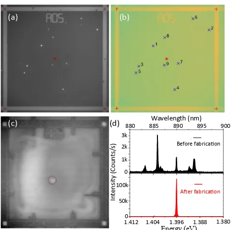
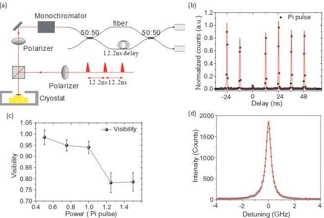
Fig. 1.(a) Schematic of the photoluminescence imaging setup used for determining QD locations en route to determinis-tic micropillar single photon source fabrication. Illumination of the alignment marks is done by a 730 nm LED, while re-moval of unwanted light entering the EMCCD camera is done through two notch filters (NFs) that block wavelengths be-tween 810 nm and 880 nm, and a long pass filter (LPF) that removes wavelengths below 700 nm. (b) Image acquired using the original photoluminescence imaging setup configuration described in Refs. [14,30], in which the illumination LED is at 940 nm. (c) Image acquired using the modified setup de-picted in (a). (d) Horizontal line cut through the image from (b), along the dashed red line. While the contrast between the QD emission and background level is high (central peak), the alignment mark contrast is limited. (e) Horizontal line cut through the image from (c), along the dashed red line. The modified imaging setup yields good contrast between the QD emission and background level as well as between the align-ment marks and background signal level. The alignalign-ment mark separation is 52µm in (b)-(e).
or more filters to reject light from the short wavelength LED before going into a sensitive electron-multiplied charge-coupled device (EMCCD) camera. Significant improvement in the per-formance of this approach has been reported in Ref. [30], where use of a high numerical aperture objective within the sample’s cryogenic environment resulted in a reduced image acquisition time (now 1 s) and lower uncertainties in the localization of the QDs and alignment mark centers (factors of 10×and 4.7×, respectively).
+ +
+ +
*
In
te
ns
ity (Coun
ts/
s)
1k 2k 3k
0
50k 100k
Energy (eV)
Wavelength (nm)
880 885 890 895 900
Before fabrication
After fabrication
1.4120 1.404 1.396 1.388 1.380
(a) (b)
[image:3.612.56.291.43.276.2](c) (d)
Fig. 2.(a) Photoluminescence image for quantum dot position extraction. The four alignment mark centers (center-to-center separation of 52µm in both the horizontal and vertical direc-tions) and center of the field are denoted by the red crosses and star, respectively. (b) Processed image in which individ-ual QDs are identified and numbered. (c) Photoluminescence image of a micropillar with a single quantum dot in the center, produced by the QD positioning technique and subsequent fabrication using aligned electron-beam lithography. (d) Spec-tra of QD 9 before (above) and after (below) fabrication of the micropillar.
While the signal-to-noise ratio of the QDs in Fig.1(b) is similar to what has been achieved in previous works, the alignment marks show very low contrast. The basic issue is that the contrast relies on a difference in reflectivity between the alignment marks and the sample at the illumination wavelength of 940 nm. For sam-ples without DBR stacks, this contrast is significant due to the large difference in reflectivity between the Au marks (>95 % reflectivity) and the GaAs surface (≈30 % reflectivity) at 940 nm. However, the DBR reflectivity is specifically engineered to be high (larger than that of Au), so that little contrast is observed when illuminating the sample at this wavelength. In fact, the ability to discern the alignment marks in Fig.1(b) is primarily due to the≈100 nm difference in height between the alignment marks and the sample surface, which results in the shadow-like dark regions surrounding the marks, as evident from a line cut through the image, shown in Fig.1(d).
Since Au is a spectrally broadband reflector but the DBR mirror has a narrower spectral bandwidth, we can adjust the illumination wavelength to regain contrast in the image. An important constraint is to continue to image the QD emission at the same time, while suppressing the QD excitation LED and unwanted emission from the sample (e.g., from the GaAs band edge and the wetting layer states). The most straightforward solution would be to move the illumination LED to a longer wavelength, where the DBR is no longer highly reflective, but the DBR bandwidth is sufficiently spectrally broad so as to require wavelengths outside of the EMCCD detection range. Instead,
we settle on an illumination wavelength of 730 nm. While in principle this 730 nm light also pumps the QDs, the intensity we use for alignment mark imaging is orders of magnitude lower than the intensity of the 630 nm light used to excite the QDs. We then use a series of filters to remove unwanted light entering the EMCCD, namely a 700 nm long pass filter to remove the reflected 630 nm pump, and two 800 nm band notch filters to remove the GaAs band edge emission near 830 nm and the QD wetting layer emission near 850 nm. The resulting image is shown in Fig.1(c), where the contrast in the alignment marks and signal-to-noise in the QD emission (Fig.1(d)), and the corresponding total position uncertainty (<10 nm), are similar to those achieved in Ref. [30]. As a consequence, the overall uncertainty in the quantum dot location within our fabricated devices is expected to mainly be limited by the uncertainty in the e-beam lithography alignment process, which is approximately 25 nm.
With the photoluminescence imaging setup optimized for work with our planar DBR samples, we proceed to use it in the deterministic fabrication of micropillar single-photon sources. Fig.2(a) shows a photoluminescence image from the portion of the sample at 4 K that we focus on in this work, acquired in a single shot with a 1 s integration time. By applying a combi-nation of a maximum likelihood estimation for localizing the QD emission and a cross-correlation method for determining the alignment mark centers [30], the nine brightest QDs within a set of alignment marks are identified with sub-5 nm spatial accuracy (one standard deviation value), and numbered from 1 to 9 based on their brightness, as shown Fig.2(b). The number of QDs to be considered for fabrication is further reduced by mea-suring the micro-photoluminescence (µPL) spectrum of each dot. We only make micropillar devices with the QDs whose exciton emission wavelength is within the resonance of the planar cavity, in order to match the frequency of QDs to the micropillars that are to be etched from the planar cavity. For example, among the nine QDs within the alignment marks defining field A05 in Fig.2(a)-(b), only QD 9 has an exciton emission around the planar cavity resonance≈890 nm (see the spectrum in the upper panel of Fig.2(d)). Thanks to the combination of wide-field illumination of the sample area and spatially-multiplexed detec-tion by the sensitive camera, our QD posidetec-tioning throughput is significantly improved with respect to scanning-based position-ing techniques, e.g., atomic force microscopy, scannposition-ing confocal micro-photoluminescence, and scanning cathodoluminescence methods. Furthermore, the compatibility of our technique with electron-beam lithography allows the creation of a wide-range of nanophotonic structures, thus offering the possibility of real-izing a variety of functional quantum photonic devices based on QDs.
(a)
(b)
0
Time (ns)
).
u.
a(
st
nu
o
C
0.0 200 400 600 800
)s
p(
e
mit
efi
L
Detuning (meV)
40
30
20
10
1.388 1.390 1.392 1.394
Energy (eV) 1 2 3 4
Δ=57 µeV
Δ=724µeV
(c)
0.3 0.6 0.9 1.2
Tempe
ra
tu
re (K)
Max
[image:4.612.46.556.45.182.2]Min
Fig. 3.(a) Temperature-dependent spectra of a micropillar with a diameter ofd≈2µm under above bandgap excitation. A strong enhancement of the emission at spectral resonance due to the Purcell effect is observed. (b) Time resolved measurements on and near resonance, revealing a dramatic reduction of the radiative lifetime. (c) A fit to the QD lifetime as a function of QD-cavity de-tuning yields a Purcell factor ofFP=7.8±1.5. The error bars in the lifetime data are determined from fitting a mono-exponential
decay to the time-resolved measurement, and are a one standard deviation value. The uncertainty in the Purcell factor represents a one standard deviation value, and is estimated from a least squares fit to the data (solid red line in (c)) according to Eq.1in the main text.
(a) (b)
Pi pulse
-24 0.0 0.2 0.4 0.6 0.8 1.0 1.2
oc
de
zil
a
mr
o
N
st
nu
).
u.
a(
Delay (ns)0 24 48 0.5
1 2 3 4 5
).
u.
a(
yti
sn
et
nI
Power 1.0 1.5 2.0 2.5 3.0( )µw
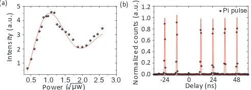
Fig. 4.(a) Measured count rate on the spectrometer versus the pulse area of the driving laser field for spectral resonance be-tween the QD and cavity mode. (b) 2ndorder autocorrelation
histogram for pulsed resonant excitation with aπ-pulse. We extract ag(2)-value as low asg(2)(0) =0.015±0.009.
allow for complication-free resonant studies, since any remain-ing metal on top of the surface would create an unacceptable amount of stray light from the pump laser.
After fabrication of the micropillars, we have verified the successful alignment of the e-beam lithography with respect to the QD positioning in our imaging setup. With the fluorescence images of micropillar devices, it is possible to visualize that 40 out of 40 selected pillars host a single quantum emitter which is well-centered in the post. Fig.2(c) shows a representative fluorescence image for one of the final devices, in which QD 9 sits in the center of a 2µm diameter micropillar highlighted by the red circle. A direct comparison between the spectra taken at the same excitation power before and after fabrication shows that the emission from the targeted exciton has been greatly enhanced by the micropillar, as shown in Fig.2(d).
3. SINGLE-PHOTON SOURCE PERFORMANCE
Now, we demonstrate that our device indeed is capable of being operated as a competitive single photon source. We investi-gate a device with a diameter ofd=2µm and the extracted Q = 4477±28 (one standard deviation uncertainty from a Lorentzian fit to the data). Figure3(a) shows a contour plot of spectra recorded from this device at various sample tempera-tures under non-resonant excitation. As we increase the sample
temperature, the single QD is subject to a spectral redshift, and spectral resonance with the cavity mode is no longer maintained. This detuning of the QD with respect to the cavity comes along with a significant reduction of the emitted light due to reduced coupling to the guided resonant mode. To determine the Purcell enhancement of the system, the device is operated under pulsed resonance fluorescence conditions. We employed polarization filtering in this experiment, analogous to previous works [8]. The decay time was recorded via a fast avalanche photon diode, triggered by the resonant laser. The decay of the emission signal as a function of the time delay for the resonant as well as the far detuned (1 meV) case is shown in Fig.3(b). From mono-exponentially decaying signals, we can extract the characteristic T1time of the QD, which is reduced to 100 ps on resonance due
to the Purcell effect. To further quantify the coupling between QD and cavity, we have carried out this experiment for 6 differ-ent detunings and plotted the resultingT1times as a function
of the spectral QD-cavity detuning (Fig.3(c)). This allows us to accurately determine the Purcell factor of our QD-cavity device by fitting the lifetime as a function of the detuning with the formula:
τ(∆) = FP,Max.
(FP,Max.∗δ+1)∗ ¯
h∗ε0∗Vm
2∗Q∗µ212, (1) whereδ= ξ2∗ ∆ω
2
c
4∗(∆2)+∆
ωc2,FP,Max.
= 3Q(λ/n)3
4π2VM is the maximal
Purcell factor,ξrepresents the orientation mismatch between the local cavity field and the dipole moment of the QD, and ∆ωcis the linewidth of the cavity mode. In addition,∆is the
detuning, }is the Planck constant divided by 2π, µ12 is the
dipole moment of the radiative transition, ε0 is the vacuum
dielectric permittivity, and Q andVmare the quality factor and
mode volume of the cavity mode respectively.
For our device, we observe a maximum Purcell factor as large as 7.8±1.5, based on the assumption that suppression of spontaneous emission off resonance is insignificant in our case. The theoretical maximum[31] ofFP,Max.=9.73 for a micropillar
[image:4.612.43.289.291.380.2](b)
(c)
ytili
bisi
V
12.2ns
Polarizer Polarizer
Monochromator (a)
12.2ns
50:50 50:50
fiber
12.2ns delay
-24 0.0 0.2 0.4 0.6 0.8 1.0
1.2 Pi pulse
oc
de
zil
a
mr
o
N
unts
(a.u.)
Delay (ns)
0 24 48
0.4 0.70 0.75 0.80 0.85 0.90 0.95 1.00 1.05
Power ( Pi pulse)
Visibility
0.6 0.8 1.0 1.2 1.4 -2 0 2 4
Detuning (GHz)
Intensity (Counts)
2000
1500
1000
500
0
(d)
-4
[image:5.612.144.472.46.267.2]Cryostat
Fig. 5.(a) Unbalanced Mach-Zehnder interferometers with a path difference of 12.2 ns, used in characterizing the indistinguisha-bility of single photons emitted by the QD micropillar source. (b) Histogram of two-photon interference with the 12.2 ns delay time. Photons with parallel polarization are prepared here. The histogram was fitted by a sum of 7 two-sided exponential functions, each convoluted with a Gaussian distribution. (c) Extracted photon indistinguishability as a function of pump power. An obvious power-related interference visibility decrease is revealed. (d) Measurement of the emission linewidth when the QD is on resonance with the micropillar mode and under continuous-wave, resonant laser excitation. A linewidth of 473 MHz±3.0 MHz is extracted from a Lorentzian fit to the data.
the value reported in [32] and scaled it with the volume of the micropillar. As we compare this number with the maximum Purcell factor in theory, we observe a slight reduction in our case from approximately 10 to 7.8. This can be a result of the positioning uncertainty and the orientation mismatch between the QD dipole moment and the local cavity field.
The strictly resonant excitation of our QD allows us to estab-lish full inversion of our effective two-level system. In a power-dependent study (Fig.4(a)) we show the characteristic Rabi-oscillation behavior as a function of the square root of the pump power, which is the key signature for the pulsed resonant driv-ing of the two level system. The red curve in Fig.4(a) shows the sinusoidal damped behavior according to the exciton-phonon coupling model. Forπ-pulse excitation, we observe count rates on the spectrometer up to≈130 000 counts per second. In order to extract the overall device efficiency of our QD-micropillar de-vice from this measurement, we carefully calibrated our setup, revealing a setup efficiency for the detected linear polarization ofηSetup= (0.325±0.01)%, where the uncertainty is due to
fluc-tuations in the power measurement and represents one standard deviation. Therefore, our device yields an overall extraction efficiency ofη= (49±4)%. Because the QD energy is still red-shifted by 57.42µeV at 4.3 K, our extraction efficiency is promis-ing when compared with the maximum extraction efficiency for the pillar in theory (η = QQpillar
2D ∗
Fp,max
1+Fp,max = (59.54±11.86)%).
The high brightness, and comparably large setup efficiency al-lows us to record quasi-background-free single photon correla-tion charts via a fiber-coupled Hanbury Brown and Twiss setup. Figure4(b) shows the recorded coincidence histogram for π -pulse excitation. The vanishing peak aroundτ≈0 ns is a clear signature of the non-classical light emission from the QD. We fit each pulse with a two-sided exponential decay convolved
with a Gaussian distribution, where the width is the time res-olution (tRes≈520 ps) of our setup. This allows us to extract
a value ofg(2)(0)via dividing the area of the central peak by the average area of the surrounding peaks, which amounts to g(2)(0) = 0.015±0.009, where the uncertainty is due to the variation in the surrounding peak area and represents a one standard deviation value.
Next, we test the coherence of consecutive emitted single photons from our device, which are excited with the repeti-tion rate of the pump laser (82 MHz). The emitted photons are coupled into an unbalanced fiber coupled Mach-Zehnder-interferometer (Fig.5(a)). One arm of the interferometer is pre-cisely adjusted to compensate for the delay (12.2 ns) between the two photons. If the early photon takes the long arm of the interferometer and the late photon the short path, both meet each other at the second 50/50 beam splitter where they can interfere if they are indistinguishable. Figure5(b) shows the measured coincidence histograms for parallel polarization of the photons for driving the system with aπ-pulse. The suppression of the central peak in Fig. 5(b) is a clear proof that our device emits highly coherent photons on demand. In order to extract the degree of indistinguishability, we slightly adjust the atten-uation in the interferometer to balance the counts before the second 50/50 fiber beam splitter (R/T≈1) and each histogram in Fig.5(b) was fitted by a sum of 7 two-sided exponential func-tions convolved with a Gaussian distribution. Therefore, we could extract the raw two-photon interference visibility with the functionυraw =1− AA⊥k = (91.1±1.9)%, where theAk was
expressed by the fitted histogram area at 0 delay divided by the average area of the 4 other peaks at -24.4 ns, 24.4 ns, 36.6 ns, 48.8 ns andA⊥ =0.5. The uncertainty is a one standard
areas. When taking into account theg(2)(0)value, we can get a corrected interference visibility ofυcorrected = (93.99±2.71)%.
By reducing the excitation power to correspond to aπ/2 pulse, excitation-induced dephasing in our system is minimized, and near-unity indistinguishability(98.5±3.2)% is fully restored, as can be seen from Fig.5(c). Finally, measurement of the QD linewidth (Fig.5(d)) by a scanning-Fabry Perot cavity under continuous-wave, resonant driving yields a linewidth of (473
±3.0) MHz, where the uncertainty is a one standard deviation value obtained from a Lorentzian fit to the data. We note that the measured linewidth is narrower than the theoretical number for a QD with a lifetime of 100 ps because the QD and cavity mode were detuned in this particular measurement; that is, the Pur-cell enhancement was less than the maximum value in Fig.3(c). On the whole, the high-accuracy positioning has resulted in an overall performance level comparable to that of recent state-of-the-art single-photon sources based on QDs [20,22,23]. A detailed comparison is provided in table I of the supplementary information.
In conclusion, we have discussed the implementation of a deterministic quantum dot -based single photon source. We apply quantum dot imaging to create our device, which is, in principle, a technology that can be used to significantly scale up the number of fabricated devices with high throughput. Our device features a Purcell factor of FP = 7.8, which is highly
beneficial for the emission of single photons close to the Fourier limit. In a power-dependent study, we demonstrate unity in-distinguishability of the emitter resonance fluorescence photons atπ/2 conditions, which are only slightly compromised to a visibility of 94 % as the two-level system is fully inverted. We believe that QD imaging represents a superior technology for the integration of single QDs into photonic architectures, as it is highly compatible with any kind of device geometry. It fur-thermore benefits from its almost scalable nature, induced by the one-shot identification of single QD positions.
4. FUNDING INFORMATION
We acknowledge financial support by the State of Bavaria and the German Ministry of Education and Research (BMBF) within the projects Q.com-H. Support by the DFG within the project SCHN1376-2.1 (DACH) is greatfully acknowledged. Y.-M. H. ac-knowledges support from the Sino-German (CSC-DAAD) Post-doc Scholarship Program. J.-L acknowledges support by the Cooperative Research Agreement between the University of Maryland and NIST-CNST, Award 70NANB10H193, National Natural Science Foundation of China (grant no. 11304102) and the Ministry of Science and Technology of China (grant no. 2016YFA0301300).
5. ACKNOWLEDGEMENTS
The authors would like to thank A. Wolf for assistance during the lithography.
REFERENCES
1. Peter Michler.Single semiconductor quantum dots. Springer, 2009.
2. P. Yao, V. S. C. Manga Rao, and S. Hughes. "On-chip single photon sources using planar photonic crystals and single quantum dots,"Laser Photon. Rev.4, 499-516 (2010). 3. T. B. Hoang, J. Beetz, M. Lermer, L. Midolo, M. Kamp,
S. Höfling, and A. Fiore. "Widely tunable, efficient on-chip
single photon sources at telecommunication wavelengths," Opt. Express20, 21758-21765 (2012).
4. C. P. Dietrich, A. Fiore, M. G. Thompson, M. Kamp and M. Kamp, and S. Höfling "GaAs integrated quantum pho-tonics: Towards compact and multi-functional quantum photonic integrated circuits,"Laser Photon. Rev.10, 870-894 (2016).
5. J. Nilsson, R. M. Stevenson, K. H. A. Chan, J. Skiba-Szymanska, M. Lucamarini, M. B. Ward, A. J. Bennett, C. L. Salter, I. Farrer, D. A. Ritchie, and A. J. Shields. "Quan-tum teleportation using a light-emitting diode,"Nat. Photon. 7, 311-315 (2013).
6. W. B. Gao, P. Fallahi, E. Togan, A. Delteil, Y. S. Chin, J. Miguel-Sanchez, and A. Imamo ˘glu. "Quantum teleporta-tion from a propagating photon to a solid-state spin qubit’" Nat. Commun.4, 3744 (2013).
7. C. Jones, D. Kim, M. T. Rakher, P. G. Kwiat and T. D. Ladd. "Design and analysis of communication protocols for quan-tum repeater networks,"New J. Phys.18, 083015 (2016). 8. Y.-M. He, Y He, Y.-J. Wei, D. Wu, M. Atature, C. Schneider,
S. Höfling, M. Kamp, C.-Y. Lu, and J.-W. Pan. "On-demand semiconductor single-photon source with near-unity indis-tinguishability,"Nat. Nanotechnol.8, 213-217 (2013). 9. E. Moreau, I. Robert, J. M. Gérard, I. Abram, L. Manin, and
V. Thierry-Mieg. "Single-mode solid-state single photon source based on isolated quantum dots in pillar microcavi-ties,"Appl. Phys. Lett.79, 2865–2867 (2001).
10. M. Pelton, C. Santori, J. Vuckovi´c, B. Zhang, G. S. Solomon, J. Plant, and Y. Yamamoto. "Efficient source of single pho-tons: A single quantum dot in a micropost microcavity," Phys. Rev. Lett.89, 233602 (2002).
11. M. Arcari, I. Söllner, A. Javadi, S. Lindskov Hansen, S. Mah-moodian, J. Liu, H. Thyrrestrup, E. H. Lee, J. D. Song, S. Sto-bbe, and P. Lodahl. "Near-unity coupling efficiency of a quantum emitter to a photonic crystal waveguide," Phys. Rev. Lett.113, 093603 (2014).
12. S. Maier, P. Gold, A. Forchel, N. Gregersen, J. Mørk, S. Höfling, C. Schneider, and M. Kamp. "Bright single photon source based on self-aligned quantum dot–cavity systems,"Opt. Express22, 8136–8142 (2014).
13. M. Gschrey, A. Thoma, P. Schnauber, M. Seifried, R. Schmidt, B. Wohlfeil, L. Kruger, J. H. Schulze, T. Heindel, S. Burger, F. Schmidt, A. Strittmatter, S. Rodt, and S. Reitzen-stein. "Highly indistinguishable photons from determin-istic quantum-dot microlenses utilizing three-dimensional in situ electron-beam lithography," Nat. Commun.6, 7662 (2015).
14. L. Sapienza, M. Davanco, A. Badolato, and K. Srinivasan. "Nanoscale optical positioning of single quantum dots for bright and pure single-photon emission,"Nat. Commun.6, 7662 (2015).
18. S. Unsleber, Y.-M. He, S. Gerhardt, S. Maier, C.-Y. Lu, J.-W. Pan, N. Gregersen, M. Kamp, C. Schneider,and S. Höfling. "Highly indistinguishable on-demand resonance fluorescence photons from a deterministic quantum dot mi-cropillar device with 74% extraction efficiency,"Opt. Express 24, 8539-8549 (2016).
19. O. Gazzano, S. Michaelis de Vasconcellos, C. Arnold, A. Nowak, E. Galopin, I. Sagnes, L. Lanco, A. Lemaître, and P. Senellart. "Bright solid-state sources of indistinguish-able single photons,"Nat. Commun.4, 1425 (2013).
20. S. Unsleber, D. P. S McCutcheon, M. Dambach, M. er-mer, N. Gregersen, S. Höfling, J. Mørk, C. Schneider, and M. Kamp. "Two-photon interference from a quantum dot microcavity: Persistent pure dephasing and suppression of time jitter,"Phys. Rev. B91, 075413 (2015).
21. S. Varoutsis, S. Laurent, P. Kramper, A. Lemaître, I. Sagnes, I Robert-Philip, and I. Abram "Restoration of photon indis-tinguishability in the emission of a semiconductor quantum dot,"Phys. Rev. B72, 041303 (2005).
22. X. Ding, Y. He, Z. C. Duan, N. Gregersen M.-C. Chen, S. Un-sleber, S. Maier, C. Schneider, M. Kamp, S. Höfling, C.-Y. Lu and J.-W. Pan. "On-demand single photons with high ex-traction efficiency and near-unity indistinguishability from a resonantly driven quantum dot in a micropillar," Phys. Rev. Lett.116, 020401 (2016).
23. N. Somaschi, V. Giesz, L. De Santis, J. C. Loredo, M. P. Almeida, G. Hornecker, S. L. Portalupi, T. Grange, C. Antón, J. Demory, C. Gómez, I. Sagnes, N. D. Lanzillotti-Kimura, A. Lemaítre, A. Auffeves, A. G. White, L. Lanco and P. Senel-lart "Near-optimal single-photon sources in the solid state," Nat. Photon.10, 340-345 (2016).
24. C. Schneider, A. Huggenberger, T. Sünner, T. Heindel, M. Strauß, S. Göpfert, P. Weinmann, S. Reitzenstein, L. Worschech, M. Kamp, S. Hofling, A. Forchel. "Site-controlled In (Ga) As/GaAs quantum dots: growth, prop-erties and device integration," Nanotechnology20, 434021 (2009)
25. A. Badolato, K. Hennessy, M. Atatüre, J. Dreiser, E. Hu, P. M. Petroff, and A. Imamo ˘glu "Deterministic coupling of single quantum dots to single nanocavity modes,"Science 208, 1158 (2005).
26. A. Dousse, L. Lanco, J. Suffczy ´nski, E. Semenova, A. Miard, A. Lemaˆitre, I. Sagnes, C. Roblin, J. Bloch, and P. Senellart. "Controlled light-matter coupling for a single quantum dot embedded in a pillar microcavity using far-field optical lithography,"Phys. Rev. Lett.101, 267404 (2008).
27. S. M. Thon, M. T. Rakher, H. Kim, J. Gudat, W. M. Irvine, P. M Petroff, D. Bouwmeester "Strong coupling through optical positioning of a quantum dot in a photonic crystal cavity,"Appl. Phys. Lett.94, 111116 (2009).
28. K. Kuruma, Y. Ota, M. Kakuda, D. Takamiya, S. Iwamoto, and Y. Arakawa "Position dependent optical coupling be-tween single quantum dots and photonic crystal nanocavi-ties,"Appl. Phys. Lett.109, 071110 (2016).
29. T. Kojima, K. Kojima, T. Asano, and S. Noda, "Accurate alignment of a photonic crystal nanocavity with an embed-ded quantum dot based on optical microscopic photolumi-nescence imaging,"Appl. Phys. Lett.102, 011110 (2013). 30. J. Liu, M. Davanco, L. Sapienza, K. Konthasinghe, J. D. Song,
A. Badolato, and K. Srinivasan. "Cryogenic photolumines-cence imaging system for nanoscale positioning of single quantum emitters,"Rev. Sci. Inst.88, 023116 (2017). 31. W. L. Barnes, G. Björk, J. M. Gérard, P. Jonsson, J. A. E.
Wasey, P. T. Worthing, and V. Zwiller. "Solid-state single photon sources: light collection strategies,"Eur. Phys. J. D 18, 197-210 (2002).