University of Warwick institutional repository: http://go.warwick.ac.uk/wrap
This paper is made available online in accordance with
publisher policies. Please scroll down to view the document
itself. Please refer to the repository record for this item and our
policy information available from the repository home page for
further information.
To see the final version of this paper please visit the publisher’s website.
Access to the published version may require a subscription.
Author(s): Green, R.J. Joshi, H. Higgins, M.D. Leeson, M.S.
Article Title: Recent developments in indoor optical wireless [Optical
wireless communications]
Year of publication: 2008
Link to published article:
http://dx.doi.org/10.1049/iet-com:20060475
Publisher statement: “© 2008 IEEE. Personal use of this material is
permitted. Permission from IEEE must be obtained for all other uses, in
any current or future media, including reprinting/republishing this
material for advertising or promotional purposes, creating new
collective works, for resale or redistribution to servers or lists, or reuse
of any copyrighted component of this work in other works.”
Recent Developments in Indoor Optical Wireless Systems
R. J. Green, H. Joshi, M. D. Higgins and M. S. Leeson
[email protected]; [email protected]; [email protected]; [email protected]
All authors are with
the:-School of Engineering, University of Warwick, Coventry, CV4 7AL, UK. First Submission Date: 15-08-2006
Revision Submission Date: 18-05-2007
Abstract
An overview of the developments in optical wireless systems viewed from the traditional
commu-nications viewpoint of transmitter, channel and receiver is presented. The trends in modulation
formats that match information to the optical wireless channel are considered. This is followed
by the discussion of recent transmitter and receiver innovations, particularly the utilisation of
diversity transceivers. As a preliminary to the following treatment, the nature and modelling of
the optical wireless channel are introduced, with particular emphasis on its unique features in
terms of transmitted power constraints and non-negativity. From the examination of
pulse-position modulation and its derivatives are preferred for more sophisticated requirements.
The recent introduction of techniques from radio systems employing subcarriers is seen to be
the most promising development in modulation techniques at present. In receiver technology,
quasi-diffuse systems employing multispot diffusion and angular diversity are significant
devel-opments. They offer lower path loss and less multipath dispersion, at a lower transmission
power compared to ‘conventional’ wide-angle diffuse systems, while providing a high level of
user mobility compared to line-of-sight transmission. These developments are helping optical
wireless systems to fulfil their promise by adopting a philosophy inspired by the radio domain
to accommodate operation within a hostile channel.
1
Introduction
Optical wireless is an interesting technology combining the mobility of radio frequency (RF)
wireless communications with the high bandwidth availability of optical communications. It
of-fers the opportunity for high-speed communications and also has some of the properties of RF,
such as the relative freedom of the user from fixed networks. The conventional RF community
has now accepted that optical wireless is part of the electromagnetic spectrum, at least, in part,
thanks to a Wireless World Research Forum White Paper [1].
The major design challenge, however, for such communication systems is in achieving a
suf-ficiently high signal-to-noise ratio (SNR) at useful data rates. Since the SNR for an optical
wireless link is proportional to the square of the average received optical signal power,
transmis-sion at higher power levels compared to the electrical channel is required. However, this power
is limited by eye safety considerations [2], and portable device power consumption limitations
suitable developments in receiver technology so as to be able to work with an acceptable level
of path loss. Signal degradation also arises from the combined effects of ambient shot noise and
intersymbol interference from multipath dispersion.
The optical wireless channel combines the filtered Gaussian-noise characteristics of conventional
wire-based RF channels with the intensity modulation/direct detection (IM/DD) constraints of
an optical fibre channel. The dominant source of noise in a non-directed optical wireless link is
background illumination consisting of fluorescent light, sunlight and incandescent light [35].
In a diffuse link, the optical wireless channel, from transmitted signal power to the detected
photocurrent, may be approximated by the additive white Gaussian-noise (AWGN) model as
shown in Fig. 1a [6]. The high bit rates and relatively slow movement of transmitter and
re-ceiver mean that the channel impulse response varies appreciably only over distances comparable
with the wavelength of the modulating signal. Hence, the optical wireless channel with diffused
non-directed radiation is viewed as time invariant over short-time scales, as the channel response
varies significantly only over a time period covering many symbols. The signal dispersion caused
by multipath optical propagation is modelled as a linear baseband impulse responser.h(t), where
r is the responsivity of the photodiode in Amperes per Watt.
A detailed channel model for a Line-of-Sight (LOS) link is presented in [7] and is depicted in
Fig. 1b. The optical LOS link can be considered as non-frequency selective, with the detected
radiant flux depending on the effective detector area, and the square of the distance between
the transmitter and the receiver. Ambient radiation is modelled as AWGN with a high DC
of the transmitterreceiver distance, and pulse extension that results from the larger time
con-stant of the detected photocurrent’s diffusion component. Much of the discussion in this paper
is concentrated on indoor optical wireless communication systems, as it is more challenging to
design an optical-LAN, and the incentives are enormous bandwidth coupled with high-speed
communications.
Generally, the optical wireless channel is intensity modulated [8, 9], as the modulation of the
phase or frequency of the light is more difficult. Since the signal modulates the optical
inten-sity (instantaneous power), the transmitted waveform,x(t), must be non-negative. The average
transmitted power is the mean of the input power signal rather than the mean square of the
signal amplitude, as in the case of the conventional linear Gaussian-noise channel. Also, as a
result of eye safety considerations, the magnitude of the transmitted power must not exceed a
prescribed value, say P.
Mathematically, the constraints on input signal in an optical wireless channel can be expressed
as
x(t)≥0 (1)
lim
T→∞ 1 2T
Z T
−T
x(t)dt≤P (2)
The other major feature is time dispersion arising from multipath effects in a diffuse link.
Directed LOS links do not suffer from multipath dispersion [10], but require alignment between
transmitter and receiver, limiting user mobility. This problem can be solved by using a
quasi-diffuse configuration, as discussed in Section 3, simultaneously maintaining multiple directed
2
Modulation
The modulation procedure in IM/DD systems may entail two stages. The first is the optional
modulation of a carrier frequency by the data signal, and the second is the modulation of the
emitted infrared light. The low-frequency components close to DC should not be used for data
transmission, to ensure stable and reliable signal transmission, because the receiver performance
is dominated by shot noise generated by ambient illumination at low frequencies. Of course,
alongside digital communication techniques there exist hybrid analogue RF-optical links, in
which the particular advantages of optical wireless can be combined with RF [11], and these
techniques may be extended for IR ad hoc networks [12].
2.1 Modulation technique characteristics
The quality of a modulation code is dictated by the reliability of transmission, the bandwidth
efficiency and the power efficiency that it offers under typical noise and multipath conditions in
the optical wireless channel.
2.1.1 Reliability:
A modulation technique should adapt the signal to the optical wireless channel in such a way
that allows reception and consequent demodulation at the receiver end within the limit of an
acceptable bit-error rate (BER). In particular, it should be able to deal with intersymbol
inter-ference and variations in the data signal DC content. Furthermore, in the case of short-range,
mobile point-to-point links (where the electrical signal consists of high or low pulses) it is
nec-essary that a long absence of a ‘zero to one’ transition does not prevent adequate sample clock
recovery with a digital phase locked loop in the receiver [13]. In addition, the modulation
because of the variations of signal power, pulse extension because of the diffusion component’s
large time constant and pulse distortion from near-field signal clipping.
2.1.2 Bandwidth Efficiency:
Since the achievable bit-rate of an optical wireless communication system is limited by the
band-width of the receiver electronics and multipath dispersion, it is important to use a modulation
technique with high-bandwidth efficiency, ηB. This is defined as the ratio of the achievable
bit-rate (Rbit) to the bandwidth (B) of the transceiver, providing a measure of the utilisation
of the bandwidth of the transceiver by a modulation technique, thus [7]
ηB=
Rbit
B (3)
2.1.3 Power Efficiency:
The eye safety power limit suggests that the modulation techniques with a high peak-to-mean
power ratio are favourable. The power efficiency (ηP) of a modulation scheme is given by the
average optical power required to achieve a given BER at a given data rate [6]. Mathematically,
ηP is defined as the ratio of energy per optical pulse to the mean energy required per bit, Eb,
for a normalised transmit pulse shape, p(t), [7] given by
ηP =
R∞ −∞p
2
(t)dt Eb
(4)
When the modulation scheme does not utilise pulsed waveforms, for example, multiple subcarrier
modulation, power efficiency is commonly measured in terms of normalised power requirement,
defined as the ratio of the power required by the modulation scheme under consideration to the
The relationship between the power efficiency and bandwidth efficiency is [7]
ηP =
ηB
DC (5)
where DC is the average duty cycle of the modulated signal, given by the average ratio of the
high pulse duration to the low pulse duration during the transmission of a long data packet.
These simple, essentially empirical quantities are commonly employed, since the problem of
an optimal information-theoretic trade-off between bandwidth and power efficiencies for optical
wireless channels remains unexplored.
2.2 Specific modulation techniques
2.2.1 Binary modulation:
A detailed comparative analysis of various binary modulation schemes including OOK,
two-pulse-position modulation (2-PPM) and subcarrier binary phase-shift keying (BPSK) is
pre-sented in [6]. It is shown that the power efficiency of OOK and 2-PPM is the same, whereas,
since BPSK consists of half the transmit pulse energy compared to OOK, its power efficiency
is <3 dB. Considering bandwidth efficiency, 2-PPM and BPSK have equal bandwidth
require-ments, being twice that needed for OOK. Thus, OOK emerges as the most suitable modulation
scheme among binary modulation schemes, but at high data rates (>10 Mbps) it suffers from a
large power penalty, because of multipath dispersion [14].
2.2.2 Multilevel modulation:
The possible candidates for multi-level modulation schemes in an intensitymodulated channel
are: L-level baseband pulse-amplitude modulation (L-PAM), subcarrierL-level
quadratuream-plitude modulation (L-QAM), multiple-subcarrier modulation (MSM) and L-level PPM (L
In L-PAM, one of L possible levels is transmitted during each symbol interval, resulting in a
reduced symbol rate, and thus a reduced bandwidth requirement [6]. However, high-level PAM
suffers from an increased power penalty compared to OOK, depending upon the value of L,
arising from the increased size of symbol alphabet, with each symbol carrying log2L bits of
information.
Subcarrier L-QAM suffers from an additional power penalty of 1.5 dB, because of the power
wasted in the DC offset common to all subcarrier techniques, plus multisubcarrier and
multi-level penalties [15]. Thus, compared with OOK, the power requirement to achieve a given bit
rate is relatively higher for subcarrierL-QAM. For example, a single subcarrier 16-QAM system
requires 4.8 dB more power compared with OOK for a given bit rate [6]. However, the bandwidth
requirement is independent of the number of subcarriers, depending only on the alphabet sizeL.
In L-PPM, the symbol interval of duration T is divided in to L sub-intervals, and the optical
signal is ‘on’ duringlth sub-interval, and ‘off’ for the rest of the symbol duration. TheLpossible
signals form an orthogonal basis for the signal sub-space spanned by the transmitted signals [16].
The bandwidth of L-PPM is approximately the bandwidth of the ‘on’ pulse, and continues to
grow with increasing L. However, for L > 2, the power requirement of L-PPM is below that
of OOK. In particular, 4-PPM has the same bandwidth efficiency as OOK, and requires 3.8 dB
less optical power to achieve a given bit rate [6]. Table 1 summarises the power and bandwidth
requirements of the modulation schemes considered so far.
than that for a single subcarrier system, and therefore the resistance to multipath dispersion
provided by using multiple-subcarriers is offset by the increased power requirement. Also,
sub-carrier techniques suffer from the increased attenuation of the multipath frequency response at
high frequencies when compared with baseband systems, so the intensity-modulation channel
favours baseband modulation schemes with low duty cycles.
Nevertheless, the resilience of MSM systems in the presence of multipath dispersion makes them
attractive for indoor optical wireless communications. Thus, much recent effort has been
di-rected towards improving the power efficiency of MSM systems. You and Kahn [17] proposed
two simple and effective approaches. The first employs block coding between the information
bits and the subcarrier modulating symbol amplitudes to increase the minimum value of the
multiple-subcarrier electrical waveform. The second replaces the fixed DC bias by a signal that
varies on a symbol-by-symbol basis. Using eight BPSK or QPSK subcarriers, these techniques
give average power reductions of ∼3.6 and 3.2 dB, respectively [17].
Another method to improve the power efficiency in MSM systems is described in [18], where a
suboptimum set of L, the peak reduction carriers (PRC), from N subcarriers, is transmitted,
with the aim of reducing the DC bias. This MSM-PRC system selects the optimum set of phases
and amplitudes, so that the average optical power requirement is reduced, mimicking what is
done in orthogonal-frequency division multiplexed (OFDM) signals [19]. The information bits
are mapped onto each subcarrier other than the PRCs independently, and hence the error rate
of the proposed system is unaffected by the PRCs. It is shown in [18] that the normalised power
requirement for a proposed MSM system with a single peak reduction carrier is 0.18 dB smaller
2.3 Recent advances in modulation techniques
2.3.1 Differential PPM (DPPM):
The DPPM is a simple modification of PPM that can achieve improved power and/ or bandwidth
efficiency, and is superior to PPM in optical multiple-access applications. A DPPM symbol is
obtained from the corresponding PPM symbol by deleting all of the ‘off’ chips following the
‘on’ chip. DPPM detection does not require symbol synchronisation, which is necessary in
case of PPM detection. It is shown in [20] that, for a given bandwidth, the DPPM requires
significantly less power than PPM. For example, the 16-DPPM provides a 3 dB optical average
power gain over 4-PPM and requires only slightly more bandwidth. The 16-DPPM also supports
the same bit rate as 16-PPM using less than half of the bandwidth, but at 1.4 dB higher average
power. The reason lies in the fact that in DPPM, the redundant ‘off’ chips are omitted without
significantly affecting the error probability. Therefore for a fixed average bit rate and fixed
bandwidth, a higher Lcan be employed with DPPM compared to PPM, resulting in improved
power efficiency. However, an unusual characteristic of DPPM is the variable bit rate nature.
This is because of the fact that DPPM symbols do not have equal durations and therefore the
time required to transmit a packet containing a fixed number of bits is not constant [18]. This
may result in transmitter buffer overflow/ underflow from packets requiring excessive/too little
transmission time, temporary violation of eye safety laws if the packet transmission time is too
small, and inefficient utilisation of network resources from the provisioning for delayed data
packets. Several techniques to reduce the bit rate variations were proposed in [20].
2.3.2 Trellis-coded PPM:
Trellis-coded modulation is designed to maximise the minimum Euclidean distance between
by using set partitioning in code design. Trellis-coded PPM has been shown to be very effective
in combating optical wireless channel multipath dispersion [21]. Multipath dispersion causes
symbols, whose chips are adjacent in time, to be separated by smaller Euclidean distances than
symbols whose chips are well separated in time. Hence, as the multipath-induced intersymbol
interference increases, the effectiveness of a Trellis-coded modulation scheme also increases. The
results obtained in [21] indicate that rate-2/3-coded 8-PPM has electrical gains of up to 5 dB
over uncoded 16-PPM for a constraint-length-10 code, with the same bandwidth requirement.
However, 7 is a more practical value of constraint length, used in the IEEE 802.11 standard to
reduce the complexity of the Viterbi decoder.
2.3.3 Rate-adaptive modulation techniques:
Although the optical wireless channel can support high bit rate transmission, it is not possible
to maintain constantly the SNR to support this because of abrupt changes in ambient noise
and variations in transmitterreceiver distance. Under adverse conditions, it is important to
maintain the link by reducing the data rate until an acceptable BER is achieved. Rate-adaptive
transmission is proposed in [22] using simple repetition codes and rate-compatible punctured
convolutional codes combined withL-PPM. Repetition codes consist of repetition of eachL-PPM
symbol RR times, where RR is the rate reduction factor. The receiver estimates the channel
conditions, and thus the data rate that can be supported for a given BER. This recommended
bit rate is conveyed to the transmitter via a feedback channel for adjustment of the transmission
rate.
Another rate-adaptive modulation scheme is based on the use of variable silence periods and
OOK formats with memory [23]. The former are used to modify the statistics of the amplitude
power ratio. This scheme provides a signalling rate with wide dynamic range, and results in
reduced complexity compared with the scheme based on repetition coding specified in the
ad-vanced infrared (AIr) standard [24].
Both techniques mentioned above represent approaches in the time domain but recently the
frequency domain-based method of adaptively multiplexing orthogonal subcarriers has emerged
[25]. This technique is analogous to adaptive OFDM in the RF domain. The proposed system
dynamically adjusts the transmission rate to the optical wireless channel conditions by assigning
suitable modulation formats to individual subcarriers to fully utilise the channel capacity. The
rate-adaptation is maintained even under a worst-case scenario by using the lowest subcarriers
(which are always suitable for transmission in the case of an optical wireless channel) over a
low-rate feedback link. The data rate is chosen on a carrier-by-carrier basis, and therefore the
system is able to adapt to a wide range of channel conditions. The throughput benefits of the
HughesHartog bit-loading algorithm over straightforward bit allocation, based on optimal power
distribution, are demonstrated in [25]. This work demonstrates that the high-level modulation
formats (QPSK, 16-QAM, 64-QAM) are efficient with benign channel conditions, whereas
low-complexity modulation formats, such as PPM, are necessary to maintain reliable transmission
under adverse channel conditions.
In [26], a capacity analysis is performed for a system using adaptive multiple-subcarrier
transmis-sion. An algorithm is developed using Lagrange multipliers for optimal optical power allocation
to individual subcarriers (which is analogous to the ‘water-filling problem’ in radio channels),
and results are derived for the theoretically achievable data-rates under different channel
parallel-independent Gaussian channels with independent noise, and the channel capacity is
given as the sum of capacities of the individual carriers. This work demonstrates the
attrac-tiveness of adaptive modulation, by exploiting the wide-varying optical wireless communication
channel characteristics.
2.3.4 Edge position modulation (EPM):
The EPM technique divides the transmission time interval into discrete slots, each of which
is slightly greater than the rise time interval plus the jitter interval of the rising edge of the
transmitted pulses [7]. Since the rise time and jitter interval are much smaller than the pulse
length, the time slots for EPM can be smaller than the time slots for PPM. Thus, with EPM,
more information can be transmitted within a certain transmission interval, as there are more
possibilities to arrange the pulses compared to PPM. The coding used in the EPM scheme is
run-length-limited (RLL) coding, ensuring that the rising edge of the pulse is not disturbed by
the previous pulse, and thus avoiding intersymbol interference. The code input is the bit stream
to be transmitted, and the outputs specify the positions where the pulses should start. The
RLL coding allows EPM to operate with relatively large pulse extensions, and hence is well
adapted to the optical wireless channel, offering increased bandwidth efficiency at reasonable
power efficiency [7].
2.3.5 Digital pulse interval modulation (DPIM):
In DPIM, each block of log2Ldata bits is mapped onto one of L possible symbols, each differs
in length [27]. Information is encoded by varying the number of empty slots between adjacent
pulses, and hence the redundancy of empty slots following a pulse in PPM symbol is removed.
Each symbol is initiated with a pulse and is followed by a number of empty slots directly
means that the overall bit rate is variable in DPIM, and the slot rate is selected such that the
mean symbol duration is equal to the time taken to transmit the same number of bits using
OOK or L-PPM achieving the same average bit rate.
The unique symbol structure of DPIM is exploited in combating intersymbol interference by
introducing guard slots in each symbol immediately following the pulse. During detection, the
slots contained within the guard slot following the correctly detected pulse are automatically
assigned zero values, regardless of the level of the sampled output. The error performance
with/without equalisation for DPIM is presented in [27].
3
Transmitter and receiver aspects
As with any mobile communication system, the objective is to provide the user with a high
degree of movement, coupled with a high data rate. In addition to modulation aspects, the
transmitter and receiver designs are also important factors in system performance. The design
techniques employed to realise them should take into account the configuration of the system.
A diffuse system requires a high-power transmitter and a sensitive receiver, because of the high
path loss from the multiple bounces incurred between the source and the receiver, limiting the
rate of modulation that can be achieved [28]. The low level of optical power often present at
the receiver makes the utilisation of optical concentrators to maximise light collection beneficial
[29]. However, the high level of ambient light presents results in shot noise from the entire
field-of-view (FOV) of the optical concentrator plus detector combination. This must be ameliorated
by optical and electrical filtering [30]. The LOS channel offers higher speed because of the
mobility. Photogenerated noise can also be reduced because of the narrower FOV employed
in the optical front-end of the receiver. An approach described in the recent literature is the
quasi-diffuse, or tracked system, employing a multi-beam transmitter and an angle diversity
receiver.
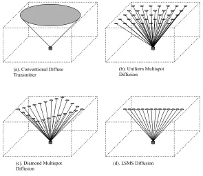
3.1 Quasi-diffuse transmitters
The purpose of the quasi-diffuse transmitter is to create multiple narrow beams targeted in
dif-ferent directions. By using such beams, the system requires lower transmitter power, has a lower
path loss and reduced multipath dispersion, in comparison with single wide-angle transmitters,
but the user still has freedom from link blockage. Fig. 2 shows some of the possible multispot
diffusion patterns that can be achieved using quasi-diffuse transmitters, including a novel line
strip multi-spot system [31].
Multispot diffusion can be achieved by implementing arrays of illuminating elements, coupled
to conventional lenses or computer-generated holograms [32]. It is also possible to target the
narrow fields towards a reflective surface, such as the ceiling as shown in Fig. 2, or provide many
direct LOS links from a base station situated on the ceiling, projecting down onto the receiver
[33].
3.2 Quasi-diffuse receivers
Angular diversity receivers (ADRs) utilise an array of narrow FOV receiving elements that are
pointed in different directions and/or have different spatial locations, combining to create a
wide-angle receiver. Each element has its own amplifier circuitry, and the system may employ
signal processing to determine which elements are receiving signals, allowing the rejection of
dispersion effects can also be mitigated by rejecting elements that receive weak signals from
reflections if an LOS link is present. Another advantage is that each element with a narrow
FOV is smaller than a single element with a wide FOV, so the capacitance of each detector is
smaller, and thus increasing the bandwidth of the system. The disadvantage of using ADRs is
the added complexity of the receiver, which has to incorporate multiple detectors, each with its
own amplifier and an overall processor.
The ADR can be either imaging or non-imaging, as shown in Fig. 3. The former employs only
one imaging optical concentrator that forms an image of the received light onto the
photodetec-tor array, thus sending the light that arrives from different directions to different detecphotodetec-tors. The
latter couples each element to a non-imaging optical concentrator with a filter, and the receiver
can then determine from where the light arrived via knowledge of the receiver orientation and
the FOV attained by each element/concentrator.
A number of non-imaging concentrators have been proposed in the past, two of the most-popular
being the hemispherical (truncated spherical) dielectric concentrator [3437], and the
rotation-ally symmetric compound parabolic concentrator (CPC) [38, 39]. Hemispherical concentrators
achieve a high FOV and gain, provided the hemisphere radius is large compared with the
detec-tor [30], and an optical filter can be placed between the concentradetec-tor and the detecdetec-tor or on the
surface of the hemisphere. Although the filter placed on the surface of the hemisphere provides a
3 dB power advantage, it has to be traded off with the increased complexity of filter fabrication
[10]. CPCs on the other hand can be designed for any FOV, and utilise thin film planar optical
filters that are easier to fabricate and tune to a desired central wavelength in the bandpass
with rejecting more background illumination. Recently, another alternative has been presented
in the form of a three dimensional dielectric totally internally reflecting concentrator or optical
antenna which also uses a planar optical filter between the concentrator and the detector, but,
unlike the CPC, it can have a variety of entrance aperture shapes, giving it a smaller size and
the ability for higher optical gain compared to the traditional CPC [29, 40].
Imaging ADRs offer two advantages. First, the bulk size of the receiver is reduced, as only one
imaging optical concentrator is needed for the whole device. Second, the photodiode array is
flat and may be fabricated into a highly scalable integrated circuit, offering high pixel density
[41].
As stated above, the ADR requires signal processing to determine which pixels should be used.
In [42], a system using multiple narrow beam transmitters and multiple narrow FOV receivers,
transmitting at 70 Mbps over a range of 4.2 m using OOK with a BER of 10−9
, compared the
effectiveness of different combining schemes. Maximal ratio combining (MRC), which performs
a weighted sum based on the signal amplitude to noise power spectral densities, and low-pass
filtering with a cut-off point appropriate to the modulation speed, emerged as the most effective
signal-combining scheme.
To quantify the effectiveness of using a quasi-diffuse system, Kahn et al. [41] compared an
imaging ADR system transmitting at 30 Mbps using OOK modulation targeting a BER of 10−9
with a conventional wide FOV single element receiver. It was found that, when considering
LOS links from a wide-angle transmitter, the use of a 7 pixel imaging receiver required 3.7 dB
number of pixels was increased to over 1000, then a 13 dB transmitter power reduction was
achieved. The work also compared MRC with simply selecting the pixel with the highest SNR,
and demonstrated that MRC required slightly less power. Moreover, if the wide angle LOS
transmitter was replaced by a multi-spot transmitter, creating a diffuse signal on the ceiling
this particular configuration required 17 dB less transmitted power. Employing the multi-pixel
ADR arrangement led to gains of up to 12 dB for greater than 1000 pixels.
In [43], the development of a combined directed (for high-speed) and diffuse link (for
connectiv-ity) system was demonstrated. In this approach, the diffuse link was provided by a high-power
laser directed at a diffusely radiating surface, and the directed link was implemented with a
vertical cavity surface emitting laser diode array with focusing lens. The imaging ADR in this
work utilised an array of avalanche photodiodes to take the advantage of their higher sensitivity
because ambient-related shot noise has less effect on diversity receivers. The use of a
microcon-troller in the ADR allowed all the pixels to be active if no LOS link was present, or selectively
activated individual pixels for LOS transmission. To obtain error-free data transmission between
the transmitter and the receiver at 1.8 m, 400 mW of power was required by the diffuse laser
transmitter, whereas only 0.35 mW was required by the LOS-directed laser diode transmitter.
The final system capability demonstrated was 155 Mbps over a range of 2 m, using a 233 MHz
DBPSK subcarrier.
The first fully integrated quasi-diffuse system was presented in [44], using custom electronics
to obtain improved performance over commercially available components. The transmitter
con-sisted of an array of resonant cavity LED’s flip-chip bonded to CMOS driver circuitry and
wavelength devices are not advanced enough for the level of integration intended and this
re-stricted transmitter power for eye safety reasons. The imaging ADR consisted of an array of pin
photodiodes flip-chip bonded to custom CMOS circuitry. The use of integrated circuitry offers
good scalability, and employing CMOS permits custom fabrication of low-cost, highly functional
devices [33]. The aim of the project was to reach 155 Mbps over 23 m, and, to date, individual
component testing within the link indicates that this will soon be accomplished.
Finally, a novel form of imaging receiver was presented in [45]. This consisted of a single
photodetector, placed on a miniaturised positioning mechanism that allowed it to move under the
focal plane of the imaging lens. Advantage was taken of the slow variation in the signal position
occurring in mobile systems, which permitted searching for the best SNR via a simple search
algorithm in real time. The system has similar benefits to the others described, in that ambient
light is rejected and power can be saved at the transmitter by reducing path loss through LOS
transmission. One drawback shown in the paper was that when the signal link was completely
blocked, the system had to search again for a connection. The aim of this project, albeit in the
simulation stage, was aimed at portable equipment applications, as the receiver complexity was
low, yet still it was able to maintain the advantages of diversity receivers over those using single
detector, wideangle receivers. The initial published simulation results predicted a 50% power
saving at the transmitter by using the single-channel imaging receiver, compared to a similar
angle diversity receiver, while also increasing the available channel bandwidth.
4
Conclusions
Optical wireless systems have now been with us for>30 years, but are seen by many as still an
diffi-culties of employing optical wireless to unlock the promise of unregulated bandwidth, security
and freedom from EMC problems. After briefly introducing the optical wireless channel, this
paper addressed the optical wireless system from the traditional communications viewpoint of
transmitterchannelreceiver.
When using binary modulation, OOK is preferred for simplicity, even though it suffers
some-what from multipath dispersion at high bit rates. For more sophisticated requirements, PPM
is attractive, with 4-PPM offering the BER performance of OOK but needing only 40% of the
power. Adding trellis coding to PPM further increases its advantage for the price of a more
complex receiver. Nevertheless, PPM is not straightforward to synchronise, and this has led
to the development of DPPM, which operates at a variable bit rate. There is also the truly
asynchronous scheme of DPIM that ameliorates the effects of intersymbol interference. In a
different vein, EPM using RLL coding to avoid intersymbol interference has also emerged over
the last few years. The most radical innovations in modulation schemes, however, have come
with the employment of rateadaptive methods inspired by the RF domain. In the time domain,
coding and silence periods have been employed, whil in the frequency domain OFDM has found
application. It is in this final area that the most promising developments are occurring, and
these will enable optical wireless communication systems to move forward from the days of low
data rate and custom laboratory demonstrations.
In the receiver domain, the introduction of ADRs has produced substantial performance gains.
Although ADRs can be imaging or non-imaging, the former offers the greatest advantages,
per-mitting a relatively small receiver and straightforward system integration. Employing ADRs
integrated circuitry.
The adoption of RF-like methods to combat the unfriendly aspects of the optical wireless channel
offers the prospect of considerable future success. In particular, this takes optical wireless closer
to commercial operation as a viable alternative to the software-only security used in standard
lower frequency RF systems.
5
References
[1] O’Brien, D.C., Katz, M., Wang, P., Kalliojarvi, K., Arnon, S., Matsumoto, M., Green,
R.J., and Jivkova, S.: ‘Short–range optical wireless communications’ (Wireless World Research
Forum, 2005)
[2] BS EN 60825–1:1994: ‘Safety of laser products, equipment classification, requirements and
user’s guide’, 1994
[3] Boucouvalas, A.C.: ‘Indoor ambient light noise and its effect on wireless optical links’, IEE
Proc., Optoelectron., 1996, 143, pp. 334–338
[4] Moreira, A.J.C., Valadas, R.T.O., and Duarte, A.M.: ‘Performance of infrared transmission
systems under ambient light interference’, IEE Proc., Optoelectron., 1996, 143, pp. 339–346
[5] Narasimhan, R., Audeh, M.D., and Kahn, J.M.: ‘Effect of electronic–ballast fluorescent
lighting on wireless infrared links’, IEE Proc., Optoelectron., 1996, 143, pp. 347–354
[6] Barry, J.R.: ‘Wireless infrared communications’ (Kluwer Academic Press, 1994)
[7] Lueftner, T., Kroepl, C., Huemer, M., Hausner, J., Hagelauer, R., and Weigel, R.: ‘Edge–position
modulation for high–speed wireless infrared communications’, IEE Proc., Optoelectron., 2003,
150, pp. 427–437
[9] Korevaar, E.J.: ‘Optical Wireless Communications V’, Proc. SPIE., 2002, 4873
[10] Kahn, J.M., and Barry, J.R.: ‘Wireless infrared communications’, Proc. IEEE, 1997, 85,
pp. 265–298
[11] Green, R.J., Sweet, C., and Idrus, S.M.: ‘Optical wireless links with enhanced linearity and
selectivity [Invited]’, J. Opt. Netw., 2005, 4, pp. 671–684
[12] Abu Baker, Z.: ‘Infrared ad–hoc networking’, PhD thesis, University of Warwick, 2007
[13] Hirt,W., Hassner,M., and Heise, N.: ‘IrDA–VFIr (16 Mb/s):modulation code and system
design’, IEEE Pers. Commun., 2001, 8, pp. 58–71
[14] Wong, K.K., O’Farrell, T., and Kiatweerasakul, M.: ‘The performance of optical wireless
OOK, 2–PPM and spread spectrum under the effects of multipath dispersion and artificial light
interference’, Int. J. Commun. Syst., 2000, 13, pp. 551–576
[15] Carruthers, J.B., and Kahn, J.M.: ‘Multiple–subcarrier modulation for nondirected wireless
infrared communication’, IEEE J. Sel. Areas in Commun., 1996, 14, pp. 538–546
[16] Audeh, M.D., Kahn, J.M., and Barry, J.R.: ‘Performance of pulse–position modulation on
measured non–directed indoor infrared channels’, IEEE Trans. Commun., 1996, 44, pp. 654–659
[17] You, R., and Kahn, J.M.: ‘Averagepower reduction techniques for multiple–subcarrier
op-tical intensity modulation’, IEE Colloquium 99/ 128, ‘Opop-tical Wireless Communications’, 22
June 1999, paper 6
[18] Teramoto, S., and Ohtsuki, T.: ‘Multiple–subcarrier optical communication system with
peak reduction carriers’, Trans. IEICE, 2004, E87–B, pp. 3385–3388
[19] Hanzo, L., Munster, M., Choi, B.J., and Keller, T.: ‘OFDM and MC–CDMA for Broadband
Multi–User Communications, WLANs, and Broadcasting’ (Wiley Press, 2003)
[20] Shiu, D.S., and Kahn, J.M.: ‘Differential pulse–position modulation for power–efficient
[21] Lee, D.C.M., Kahn, J.M., and Audeh, M.D.: ‘Trellis–coded pulse–position modulation for
indoor wireless infrared communications’, IEEE Trans. Commun., 1997, 45, pp. 1080–1087
[22] Diana, L., and Kahn, J.M.: ‘Rate–adaptive modulation techniques for infrared wireless
communications’. IEEE Int. Conf. Commun. (ICC 1999), pp. 597–603
[23] Garcia–Zambrana, A., and Puerta–Notario, A.: ‘Novel approach for increasing the peak–to–average
optical power ratio in rate–adaptive optical wireless communication systems’, IEE Proc.,
Opto-electron., 2003, 150, pp. 439–444
[24] IrDA: Advanced infrared physical layer specification, (AIrPHY)–Version 1.0, 1998
[25] Grubor, J., Jungnickel, V., and Langer, K.: ‘Rate–adaptive multiple sub–carrier–based
transmission for broadband infrared wireless communication’. National Fiber Optic Engineers
Conf., 2006, p. 10
[26] Grubor, J., Jungnickel, V., and Langer, K.: ‘Capacity analysis in indoor wireless infrared
communication using adaptive multiple subcarrier transmission’. Proc. 7th Int. Conf.
Trans-parent Optical Networks 2005 (ICTON 05), pp. 171–174
[27] Ghassemlooy, Z., Hayes, A.R., and Wilson, B.: ‘Reducing the effects of intersymbol
inter-ference in diffuse DPIM optical wireless communications’, IEE Proc., Optoelectron., 2003, 150,
pp. 445–452
[28] Carruthers, J.B., and Kahn, J.M.: ‘Modeling of nondirected wireless infrared channels’,
IEEE Trans. Commun., 1997, 45, pp. 1260–1268
[29] Ramirez–Iniguez, R., and Green, R.J.: ‘Optical antenna design for indoor optical wireless
communication systems’, Int. J. Commun. Syst., 2005, 18, pp. 229–245
[30] Street, A.M., Stavrinou, P.N., O’Brien, D.C., and Edwards, D.J.: ‘Indoor optical wireless
systems a review’, Opt. Quant. Electron., 1997, 29, pp. 349–378
performance for high speed indoor diffuse infra–red wireless transmission’, IEE Proc.,
Optoelec-tron., 2004, 151, pp. 46–52
[32] Eardley, P.L., Wisely, D.R., Wood, D., and McKee, P.: ‘Holograms for optical wireless
LANs’, IEE Proc., Optoelectron., 1996, 143, pp. 365–369
[33] O’Brien, D.C., Faulkner, G.E., Jim, K., Zyambo, E.B., Edwards, D.J., Whitehead, M.,
Stavrinou, P., Parry, G., Bellon, J., Sibley, M.J., Lalithambika, V.A., Joyner, V.M., Samsudin,
R.J., Holburn, D.M., and Mears, R.J.: ‘High–speed integrated transceivers for optical wireless’,
IEEE Commun. Mag., 2003, 41, pp. 58–62
[34] Savicki, J.P., and Morgan, S.P.: ‘Hemispherical concentrators and spectral filters for planar
sensors in diffuse radiation fields’, Appl. Opt., 1994, 33, pp. 8057–8061
[35] Marhic, M.E., Kotzin, M.D., and van den Heuvel, A.P.: ‘Reflectors and immersion lenses
for detectors of diffuse radiation’, J. Opt. Soc. Am., 1982, 72, pp. 352–355
[36] Kahn, J.M., Barry, J.R., Audeh, M.D., Carruthers, J.B., Krause, W.J., and Marsh, G.W.:
‘Non–directed infrared links for high–capacity wireless LANs’, IEEE Pers. Commun., 1994, 1,
p. 12
[37] Barry, J.R., and Kahn, J.M.: ‘Link design for non directed wireless infrared
communica-tions’, Appl. Opt., 1995, 34, pp. 3764–3776
[38] Ho, K., and Kahn, J.M.: ‘Compound parabolic concentrators for narrowband wireless
infrared receivers’, Opt. Eng., 1995, 34, pp. 1385–1395
[39] Wasiczko, L.M., Smolyaninov, I.I., and Davis, C.C.: ‘Analysis of compound parabolic
con-centrators and aperture averaging to mitigate fading on free–space optical links’, Free Space
Laser Communication and Active Laser Illumination III (Eds. Voelz, D. G. and Ricklin, J. C.),
Proc. SPIE, 2004, 5160, pp. 133–142
[41] Kahn, J.M., You, R., Djahani, P., Weisbin, A.G., Teik, B.K., and Tang, A.: ‘Imaging
diversity receivers for high–speed infrared wireless communication’, IEEE Commun. Mag., 1998,
36, pp. 88–94
[42] Carruthers, J.B., and Kahn, J.M.: ‘Angle diversity for nondirected wireless infrared
com-munication’, IEEE Trans. Commun., 2000, 48, pp. 960–969
[43] Jungnickel, V., Forck, A., Haustein, T., Kruger, U., Pohl, V., and von Helmolt, C.:
‘Elec-tronic tracking for wireless infrared communications’, IEEE Trans. Wirel. Commun., 2003, 2,
(5), pp. 989–999
[44] O’Brien, D.C., Faulkner, G.E., Zyambo, E.B., Jim, K., Edwards, D.J., Stavrinou, P., Parry,
G., Bellon, J., Sibley, M.J., Lalithambika, V.A., Joyner, V.M., Samsudin, R.J., Holburn, D.M.,
and Mears, R.J.: ‘Integrated transceivers for optical wireless communications’, IEEE J. Sel.
Top. Quantum Electron., 2005, 11, pp. 173–183
[45] Castillo–Vazquez, M., and Puerta–Notario, A.: ‘Single–channel imaging receiver for optical
Table 1: Comparison of various binary and multilevel modulation schemes, adapted from [6]
Modulation Scheme Optical power requirement Bandwidth requirement
OOK √N0RBQ−1(BER) RB
2-PPM √N0RBQ−
1
(BER) 2RB
BPSK √2N0RBQ−1(BER) 2RB
L-PPM (L−1/√log2L)√N0RBQ−
1
(BER) RB/log2L
N-L-QAM √4N(√L−1/√log2L)√N0RBQ−1(BER) 2RB/log2L
L-PPM (1/√0.5Llog2L)√N0RBQ−
1
(BER) LRB/log2L
N0,noise power spectral density
RB,required bit rate
Figure 1: Channel modes for optical wireless transmission. (a) Equivalent channel model for
diffused non-directed optical wireless link. (b) Physical model of line-of-sight (LOS) optical
[image:27.595.132.456.397.624.2]Figure 2: Types of multispot diffusion patterns.
Figure 3: Receiver configurations. (a) Single element receiver. (b) Angle diversity receiver. (c)
[image:28.595.146.448.447.643.2]![Table 1: Comparison of various binary and multilevel modulation schemes, adapted from [6]](https://thumb-us.123doks.com/thumbv2/123dok_us/9737183.474597/27.595.132.456.397.624/table-comparison-various-binary-multilevel-modulation-schemes-adapted.webp)