Workflow Environment
Paul Fahey
A dissertation submitted to the University of Dublin,
in partial fulfillment of the requirements for the degree of
Master of Science in Computer Science
I declare that the work described in this dissertation is, except where otherwise stated, entirely my own work and has not been submitted as an exercise for a degree at this or any other university.
Signed: ___________________ Paul Fahey
September 1999
Permission to lend and/or copy
I agree that Trinity College Library may lend or copy this dissertation upon request.
Signed: ___________________ Paul Fahey
There is a need to revise existing (successful) software subsystems. One can’t afford
to develop a bespoke system, as done previously, so therefore ‘shrink wrapped
solution sets’ have to be realised. The problem is how to integrate heterogeneous
components to support specific, sometimes unique, enterprise business processes.
One approach is the use of Workflow Engine to co-ordinate and enact distributed
components based on explicitly represented business processes. An important element
of any Workflow Engine is the exchange of input parameters and output results
between components. Traditionally components invoke each other and pass data
directly into each other. However, in Workflow Engines component invocation is
performed by the engine and not performed directly between components.
Performance would deteriorate if all data flow needed to pass through the Workflow
Engine itself. A more efficient approach is to provide a shared component data
exchange, responsible for the storage, management and retrieval of data, which is
I would like to thank my supervisor Vinny Wade, for the advice and help that he has
given me during the dissertation. I would also like to thank Brian Cullen , John Fuller,
Sinead Muldowney, Andrew Nolan, and Cliff Redmond for the help and very useful
support during the dissertation.
Also a thanks is due to the classmates of the MSc Networks and Distributed Systems
1. INTRODUCTION ……… 1
1.1 INTRODUCTION ……… 3
1.2 OBJECTIVES ………. 3
1.3 TECHNICAL APPROACH ……… 3
2. WORKFLOW OVERVIEW ……… 5
2.1 WORKFLOW OVERVIEW ……… 5
2.2 TYPES OF WORKFLOW SYSTEMS ……….. 6
2.3 WORKFLOW MODEL ……… 9
2.3.1 WfMC Reference Model ……….. 9
2.4 PROCESS MODELLING ……… 11
2.5 SURVEY OF DATA EXCHANGE APPROACHES IN WFMS PROTOTYPES 11 2.5.1 ORBWork ……… 11
2.5.2 The Mentor Projects ………. 13
2.5.2.1 Mentor ………. 13
2.5.2.2 Mentor-Lite ……….. 14
2.5.3 Panta Rhei ……… 16
2.5.4 Exotica/FMQM with Lotus Notes ……… 17
2.6 SERENE WORKFLOW ENGINE ……….. 19
2.6.1 Knowledge Server ………. 21
2.6.2 Scheduling Management Activities ……… 21
2.6.3 Workflow Information Server ……….. 21
2.6.4 Workflow Dispatcher ……….. 22
2.6.5 Component Adaptors ……….. 22
2.6.6 Shared Component Data Server/SDE ……… 22
2.7 DATA INTEGRATION ……… 23
2.7.1 Data Integration of Prototypes ……… 23
2.7.2 Data Integration Options ……….. 25
2.7.2.1 Centralised Database, Distributed Access ………… 25
2.7.2.2 Partitioned Databases ……… 26
2.7.2.3 Distributed Databases ……… 26
2.8 ENABLING DISTRIBUTED OBJECT TECHNOLOGY ………. 27
2.8.1 The Component Model ……….. 27
2.8.2 Workflow and the Component Model ……… 28
2.8.3 The CORBA Component Model ……… 29
3.2 DATA INTEGRATION IN THE SERENE ARCHITECTURE ………… 34
3.3 DIFFERENT APPROACHES TO DATA INTEGRATION ………… 36
3.3.1 File Based Storage Approach ……….. 36
3.3.2 DBMS Storage Approach ……….. 37
3.3.3 Memory Cache Approach ……….. 38
3.3.4 Cache & DBMS Approach ……….. 38
4. DESIGN ……… 39
4.1 OVERVIEW ………. 39
4.2 COMPARISON TO RELATED RESEARCH ……… 41
4.3 ACCOUNTING BUSINESS PROCESS ……… 42
4.4 DATA FLOW MODEL ……… 44
4.5 DESIGN OF THE SHARED DATA EXCHANGE (SDE) ………. 47
4.6 DATABASE DESIGN ……… 50
4.7 SUMMARY ………. 52
5. IMPLEMENTATION ……… 53
5.1 TECHNOLOGIES USED IN THE PROJECT ……… 53
5.2 SDE IMPLEMENTATION ……… 55
5.2.1 CORBA Process ……… 55
5.2.2 IDL Interface ……… 55
5.2.3 CORBA ‘Any’ ……… 57
5.2.4 Data Description ……… 57
5.2.5 Description of Classes ……….. 59
5.2.6 Database Implementation ……….. 66
6. EVALUATION ……… 69
6.1 SDE AND DATA EXCHANGE IN A COMPONENT BASED WORKFLOW ENVIRONMENT ……….. 69
6.2 DATA STORAGE & RETRIEVAL ……….. 71
6.3 APPLICATION EVALUATION ……….. 73
6.4 ACCOUNTING BUSINESS PROCESS EVALUATION ………. 74
6.5 TESTING EVALUATION ……… 75
7. CONCLUSIONS ……… 76
7.1 ACHIEVEMENTS ……… 76
7.2 PERSONAL ACHIEVEMENTS ……….. 77
APPENDIX A IDLs ……….… 80
A.1 m_SdxTypes.idl ……… 80
A.2 RETSubM.idl ……… 83
A.3 m_ChargeContol.idl ……… 86
A.4 m_TariffControl.idl ……… 88
A.5 m_BillControl.idl ……… 90
APPENDIX B Database Schema ……… 92
ABBREVIATIONS ……… 93
Figures:
Figure 1: Sample Business Process for an Expense Request ... 5
Figure 2: A Rough Characterisation of Workflow ……… 8
Figure 3: The Workflow Management Coalition Workflow Reference Model 9 Figure 4: The METEOR2 Architecture ……… 12
Figure 5: Client/Server Architecture of Mentor ……… 14
Figure 6: The Mentor-Lite Architecture ……… 15
Figure 7: The Panta-Rhei Architecture ……… 16
Figure 9: Co-ordination of distributed workflow and data management 18 Figure 10: The Serene Architecture ……… 20
Figure 11: Basic design of the SDE ……….... 39
Figure 12:Data flow of the Store Method ... 40
Figure 13:Data flow of the Retrieve Methods ……… 40
Figure 14: The Accounting Business Process (Flowthru) ……… 43
Figure 15: Data Flow Analysis of the Accounting Business Process ……… 45
Figure 16: Design of the SDE ……… 47
Figure 17: Design of the SDE including the Accounting Business Process Bridge ……… 48
Figure 18: Graphical Representation of database design solutions ……… 51
Figure 19: SDE Implementation – all classes ……… 60
Figure 20: Hashtable of Hashtables that represents the memory cache of the SDE ……… 66
Tables:
Table 1: Summary of the WfMC Reference Model ……… 12Table 2: Variables that make up the input parameter for activity 17 ……… 46
Table 5: Tbl_IterMap that is implemented in the SDE
1. Introduction
1.1 Introduction
There is a trend in software engineering towards distributed componentisation of
software elements and the use of workflow to co-ordinate distributed component
execution. A Workflow Management System (WFMS) as defined by the Workflow
Management Coalition (WfMC), is a system that defines, creates, and manages the
execution of workflows through the use of software, running on one or more
workflow engines, which is able to interpret the process definition, interact with
workflow participants and, where required, invoke applications (or components)
[WfMC]. Componentisation allows developers to take advantage of software reuse,
and enables organisations to build on existing applications therefore avoiding the need
to develop systems from scratch.
Within the WFMS there are various components that tackle activities that need to be
completed as described above. These components need access to some sort of
repository to be able to use input parameters and then store the output parameters.
Another view of this issue is that each process, and therefore each component needs to
be able to invoke data to either test conditions on the state of each task, or to use data
to complete the activity. The results of the process, the output data, must be stored
somewhere, as they may need to be revisited at some stage in the future. It would be
unwise to discard the data produced from the process. The workflow engine is
responsible for the scheduling of the processes that must be completed in the WFMS.
The difficulty in this storage of data is obviously how and where to store the data, and
also how the components invoke the data contained in it. The goal is to have an
efficient data storage system that will allow the WFMS to execute more efficiently.
This entails taking the data storage function away from the workflow engine itself. In
removing this functionality from the workflow engine one is augmenting its capacity
as a co-ordination tool, and therefore improving its efficiency, and speed in
Manager must be implemented. A data manager of course could allow additional
functionality to be added [on the data manager side], which would be difficult to build
into the workflow engine [Alon97a].
A business process can be separated into a number of predefined activities. Each
activity is viewed as separate to the other activities in the business process, The
business process, is added to a work list. The work list gives the state of all business
process’, in the WFMS. A business process is executed by a WFMS as each activity is
completed. The business process is completed when all its activities have been
completed, only then is it signed off, and removed from the work list. An example that
is regularly used is the process of an expense form that passes through the different
departments of an organisation, so that it can be authorised by the different
departments. The business process is the complete authorisation of the expense form.
An example of an activity can be considered the authorisation by one department.
There is a distinction to be made with regards to the data that is used in a WFMS.
There are control data and production data. Control data relates to controlling the flow
of a process through a WFMS, whether an activity should be initiated, or whether it
should wait until the completion of another activity. Control data is considered
persistent data and therefore a method of retaining this data is important. Production
data relates to the input parameters and the output data of an activity or business
process, and can therefore be classed also as persistent data. This is where the data
manger in this project is needed, to store the production data. Building this separately
to the workflow engine eases the load on the workflow engine. Also, invocation of the
data by components, or different applications would be better served by a data
manager rather than the workflow engine itself, as the engine should deal more with
the scheduling and co-ordinating of the activities in a business process. Most WFMS
have a central repository that contains control data, i.e. application data employed to
evaluate the transition conditions governing the control flow, and this suggests that
the past work done on WFMS neglected the production data flow aspects and focused
What is being investigated here is the role of database technology and research in the
area of WFMS in relation to the exchange of production data. It is hoped that it will be
possible to identify the role that database technology can take in improving the
WFMS, and to identify the database technology that would be best suited to the
Serene Workflow Engine, the WFMS under development in the Computer Science
department of Trinity College Dublin. The data manager must be a shared component
data server (SCDS), as there will be different components, invoking the data
contained in the SCDS, and storing output data that may be used by other components
for other activities. It is seen that the SCDS should be as intelligent as possible,
therefore easing the load on the workflow engine, and on the components.
1.2 Objectives
The objective of this thesis is: to investigate the issues and propose a solution(s), to
support information flow between components in an engine based workflow
environment.
This will be carried out as follows:
• Research into how other Workflow Engines exchange component data.
• Design of the integration of a Workflow application data exchange
• Implementation of the design
• Evaluation of the implementation
1.3 Technical Approach
The first phase of this project is to investigate WFMS prototypes that have been
developed and how they approach the area of production data exchange. The
investigation will include an analysis of their modes of exchanging data, and the
examination of Component Models is also necessary to identify their methods in
addressing persistent storage.
Phase two of the project is to design a data exchange for the Serene WFMS and
integrate this with version 2 of the Serene workflow engine which is being developed.
Interfaces are to be designed so as to allow the integration of the design of the data
exchange with the Serene workflow engine.
Phase three involves the implementation of the data exchange, once an adequate
design has been proposed.
Phase four of the project is the evaluation of both the design and the implementation.
The evaluation will consist of a comparison with the research carried out in the first
phase, an evaluation of the objectives and the achievements of the project, and finally
2. Workflow Overview and Systems
2.1 Workflow Overview
Workflow is defined as a collection of tasks organised to accomplish some business
process (e.g. processing purchase orders over the phone, processing insurance claims)
[Geog95]. A business process can be completed automatically by a software system,
manually by human intervention, or both of these. It is seen as the automation of a
business process.
A business process is broken down into a number of steps or activities, which can be
drawn as an annotated directed graph, which defines the process in a step by step
fashion. Each step is completed in a structured manner. The business process is
represented as a workflow, i.e. computerised models of the business process, which
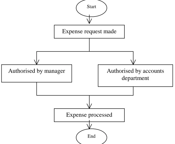
specify all the parameters involved in the completion of the process. Figure 1 is an
example of a business process, and the example used is an expense from passing
[image:14.595.156.443.449.685.2]through an authorisation process.
Figure 1: Sample Business Process for an Expense Request
Expense request made
Expense processed
Authorised by accounts department Authorised by manager
Start
Workflow is seen in many areas as a complement to Business Process Re-Engineering
(BPR), which is a term that has crept into the corporate world and is dominating most
system development projects today. A WFMS is used to co-ordinate, and streamline
the business process. The parameters that are involved in the completion of a process
range from defining the individual steps (entering customer information, consulting a
database, getting a signature), to establishing the order and conditions in which the
steps must be executed including aspects such as data flow between steps, who is
responsible for each step, and the applications (databases, editors, spreadsheets) to use
with each activity [Alon97b].
Each sub-task, or activity, is passed from one participant to another and it is
automatically, or manually, completed once the start condition for the activity has
been passed. The WFMS provides the ability to specify, execute, report on, and
dynamically control workflow [Geog95]. This is one form of a WFMS. The other
occurs by the activity being initiated in a controlled sequence by the WFMS, that is,
once an activity is completed the WFMS is notified and it initiates the next activity in
the sequence.
2.2 Types of Workflow Systems
Workflow systems fall into two broad categories:
• Forms and messages based workflow systems which perform electronic routing of forms to user’s e-mail in-boxes
• Engine based workflow systems, which communicate with humans or components via specialised client software [Wade99]
Workflow systems can be viewed in another fashion, as will be discussed in the rest of
this section. There are four main categories of WFMS [Alon97b], although some
sources suggest that there are only three. The four categories that are specified are as
follows:
• Ad hoc
• Collaborative
• Production
The differences that these categories are based on are: a) repetitiveness and
predictability of workflows and business processes; b) how the workflow is initiated
and then controlled; and c) requirements for WFMS functionality.
Administrative workflows have steps that are well established, and the set of rules
governing the process is known by everybody involved. They are simple repetitive
predictable processes that have simple co-ordination rules. An example of this would
be the routing of an expense report through an authorisation process, or the
registration of a student in university. There is little complexity to the workflow
process here, and the WFMS in this category would be classed as non-mission critical
[Geog95]. In this category it is the users that are actively prompted to perform their
tasks.
Ad Hoc workflows are similar to administrative except for the fact that they tend to be
created to deal with exceptions, or where there is no set pattern for moving
information among people. Therefore the ordering, and co-ordinating of the activities
is controlled by human participants. They are intended to support short-term activities.
An important point of this category of WFMS is that activity ordering, and
co-ordination decisions are made during the performance of the workflow. An example
of this is that when an activity has been completed the WFMS will then see who is
available to perform the next activity, and the activity will be placed in the worklist of
that participant.
Collaborative workflows, can be classed in the Ad Hoc category, but can also be
viewed as a category on its own. This is the extra category that is not mentioned in
most literature. Unlike the other categories, which are based on forward-directed
tasks, the collaborative category includes those tasks that are iterative over the same
by all parties and, there might have been several toing-and-froing by the authors in the
process of reaching agreement. It would be very difficult to model such a process
using tools that are not geared for collaboration since it is impossible to predefine the
steps to follow [Alon97b]. Most of the co-ordination is done by the human participant,
so it can be argued that these types of processes don’t count as being defined as
WFMSs.
Production workflows involve repetitive and predictable business processes. They can
be classed as the implementation of critical business processes. This means that they
are directly related to the function of an organisation. An example of this would be the
processing of insurance claims or loan applications. Co-ordination and ordering of
activities can be automated, but the automation of a production workflow is
complicated due to the fact of, a) information process complexity, and b) accesses to
multiple information systems to perform and retrieve data for making decisions. These
[image:17.595.108.413.429.622.2]WFMS tend to be large scale, and have to deal with heterogeneous environments.
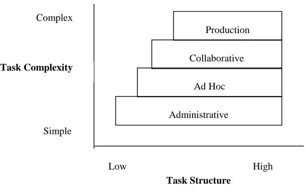
Figure 2: A Rough Characterisation of Workflow
Figure 2, above [Alon97b], shows the four categorisations in relation to each other,
based on task structure and task complexity. As can be seen a production workflow is
the most complex and the most highly structured. This is due, as stated above, to the
Administrative Ad Hoc Collaborative
Production
Task Structure Task Complexity
Complex
Simple
information process involved in the workflow, and the fact that the activities are
mostly automated.
2.3 Workflow Model
At the centre of any WFMS is the business process, and a workflow is a computerised
model of the business process. There therefore needs to exist a set of rules
implemented by a WFMS so that it can execute workflows by use of software that is
driven by the computerised workflow model.
2.3.1 WfMC Reference Model
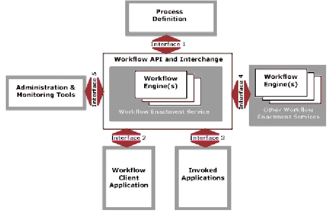
Figure 3 is a graphical representation of the workflow model as given by the
Workflow Management Coalition (WfMC) [WfRe94]. This is the standard that the
WfMC has set down so that WFMSs can at least have a common understanding, and
to prevent the growth of completely unrelated WFMS. Figure 2 illustrates the major
[image:18.595.102.441.440.659.2]components and interfaces within the workflow architecture.
Figure 3: The Workflow Management Coalition Workflow Reference Model
Working Groups Objectives
systems, identifying their characteristics,
functions and interfaces. Development of
standard terminology for workflow
systems.
Process Definition
Tools Interface (1)
Definition of a standard interface between
process definition and modelling tools
and the workflow engine(s).
Workflow Client
Application Interface (2)
Definition of APIs for client applications
to request services from the workflow
engine to control the progression of
processes, activities and work-items.
Invoked Application
Interface (3)
A standard interface definition of APIs to
allow the workflow engine to invoke a
variety of applications, through common
agent software.
Workflow Interoperability
Interface (4)
Definition of workflow interoperability
models and the corresponding standards
to support interworking.
Administration & Monitoring Tools
Interface (5)
The definition of monitoring and control
functions.
Conformance To develop the Coalition’s policy on
product conformance against its
specifications and agree an approach to
[image:19.595.81.511.69.613.2]vendor certification.
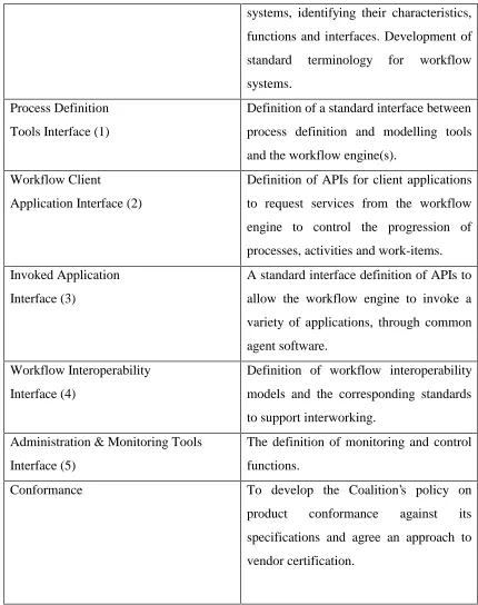
Table 1: Summary of the WfMC Reference Model
Table 1 [WfRe94] gives a summary of the different parts of the reference model, as
shown in Figure 3, that the WfMC have set as standards. An important point to note in
this model is that interfaces 2 and 3 are same, although originally they were specified
as two different interfaces. Over time they have been recognised as having the same
2.4 Process Modelling
Modelling a process involves capturing the business process. Usually this would
involve interviews with experts that have domain knowledge about the process. Once
enough knowledge has been gathered about the process the workflow specification is
performed to capture the process which requires a workflow model [Geog95]. This
workflow model consists of a set of concepts that describe the process, the activities
and the dependencies among the activities.
2.5 Survey of Data Exchange Approaches in WFMS Prototypes
This section introduces the prototype WFMS that were investigated, and their
methods of data exchange.
2.5.1. ORBWork
ORBWork is a reliable and fully distributed CORBA based enactment system for the
METEOR2 WFMS. ORBWork supports scalable software architecture,
multi-database access, as well as error detection and a recovery framework that uses
transactional concepts. The workflow specification created in the designer is stored in
an intermediate format called the Workflow Intermediate Language (WIL) which is
similar in structure and semantics to the Workflow Process Definition Language
(WPDL) of the WfMC. The WIL specification contains all the dependencies between
activities and the data objects that are passed among the different activities. The
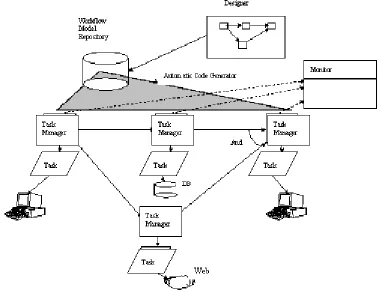
runtime system of the METEOR2 system is divided into two types of components:
Figure 4: The METEOR2 Architecture
A task manager is started usually by its predecessor by a method called Activate. This
method starts the task manager, and it also passes it the necessary parameters for the
task manager to begin. One of the parameters that it passes is a list of all the data
objects that the task manager will need [Das97]. The input parameters are ’unpacked’,
and once the task/activity has completed, a Save method is called to save the output
parameters. The save method is provided by the data object, or by using the persistent
object services of CORBA. It is the workflow code generator, the designer, that
creates an appropriate IDL interface for each data object, as it processes the WIL
specification. This WFMS is considered to be a production workflow.
2.5.2. The Mentor Projects
There are two projects that have been developed under the Mentor project. There is
the original Mentor project, and arising from that the Mentor-Lite project was
developed. The Mentor-Lite project has approached the development and integration
2.5.2.1 Mentor
The Mentor architecture, as shown in Figure 5, is generally designed as an open
modular architecture where further components can be added, and components can
easily be replaced by alternative implementations. The invoked applications of
activities are run at the client sites. An Object Request Broker (ORB), which is part of
the CORBA architecture, is integrated to cope with the potential heterogeneity of the
invoked applications that belong to the workflow [Muth98]. Orbix is used as the
CORBA compliant ORB.
The workflow specification is based on state and activity charts. Activity charts
specifies the data flow between activities, in the form of a directed graph with the
items as arc annotations. State Charts reflect the behaviour of a system in that they
specify the control flow between activities [Muth98]. The workflow specification is
partitioned based on the assumption that for each activity of the activity chart there is
a corresponding department or business unit that carries out the activity. Therefore
each activity can be assigned to a workflow server of the corresponding department or
business unit. States are then assigned to activities. The state chart is then
Figure 5: Client/Server Architecture of Mentor
2.5.2.2 Mentor-Lite
The Mentor-Lite project is a lightweight WFMS based on the Mentor WFMS. The
view taken is that a WFMS is integrated within environments that already have
solutions for implementing control flow. Other WFMS typically involve
implementing the application’s control flow exclusively by the WFMS; the control
flow in this type of WFMS would be specified and implemented from scratch. In most
cases it is rare that a business process will be computerised from scratch. There are
two architectural requirements of the Mentor-Lite project:
• A stepwise integration of workflow management functionality into existing environments must be supported. This requires the integration and
• A workflow management system must facilitate the implementation and
seamless integration of system extensions. Applications must not suffer
from runtime overhead or large system footprints caused by system
extensions unless their functionality is actually exploited [Muth99].
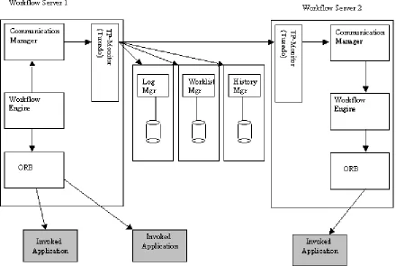
As shown in figure 6 the basic building block is an interpreter for workflow
specifications based on state charts. The communication manager (ComMgr) and the
log manager (LogMgr) are closely integrated with the workflow interpreter. These
three components make up the workflow engine. The TP-Monitor, Tuxedo, is used to
deliver synchronisation messages, but it is hypothesised that CORBA will replace this.
Applications are connected to the workflow engine by specific wrappers, and these are
[image:24.595.99.508.376.639.2]basic communication interfaces using CORBA.
Figure 6: The Mentor-Lite Architecture
It is viewed that data flow is not within the scope of research of this project. The data
Only data that is relevant to the control flow behaviour is caught. The assumption is
that computerised business processes usually exist when the WFMS is introduced. So,
there is also a kind of data flow implementation, e.g. via pipes or temporary database
tables. Mentor-Lite proposes to use this existing data flow solution [Gill99]. This
WFMS is a production workflow WFMS
2.5.3 Panta Rhei
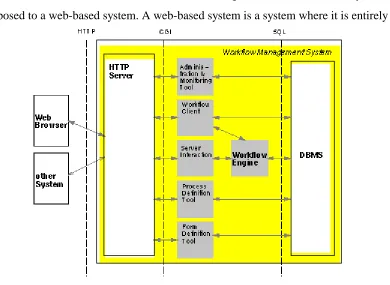
Panta Rhei’s architecture is based on Web technologies. It is a web-enabled system, as
[image:25.595.105.495.259.544.2]opposed to a web-based system. A web-based system is a system where it is entirely
Figure 7: The Panta-Rhei Architecture
run over HTTP. As can be seen from figure 7 there is an HTTP server in the Panta
Rhei architecture between the client web browser and the WFMS, and subsequently
no other communication occurs over HTTP. The interface of a user to Panta Rhei is
integrated in a web browser, therefore allowing any user with a web browser to
interact with the Panta Rhei WFMS, and thus participate in a workflow. The
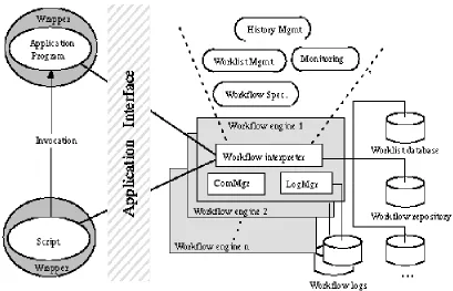
This WFMS is a forms based system. The architecture differs from the WfMC
reference model (Section 2.3.1), and the workflow engine is a relatively small
component containing the process interpreter [Eder98]. As can be seen from figure 7
all the other components in the WFMS are connected directly to the database
management system (DBMS). The WFMS is implemented in Java, and connects to
the database using Java Database Connection (JDBC).
2.5.4 Exotica/FMQM with Lotus Notes
Another research project that has been carried out does not involve the development
of a prototype, rather it pulls together the functionality of two commercial products:
FlowMark as the workflow engine, and the replication capabilities of Lotus Notes as
the support system for distributed data management. Exotica/FMQM (FlowMark on
Message Queue Manager) is the distributed version of FlowMark based on a generic
queuing system with recoverable queues [Alon97a].
It was viewed in this research that the managing of data flow has been partially
ignored by most commercial products, and the objective was to have a system that
took the management of the data flow away from the workflow engine. This enables
the workflow engine to concentrate on the scheduling of activities. Added
functionality can be embodied in the data manager, which the workflow engine would
not be envisioned containing. A definition that must be noted in this sub-section is the
use of the term node. This is used to represent a physical machine.
The workflow model is enacted by Exotica/FMQM and this is where the business
processes are instantiated, and subsequently the activities that make up the business
processes are also instantiated. The Exotica/FMQM is a combination of a production
and administrative workflow.
Within this system there is a distinction made between the control node and the data
node. The control node is where the activity is carried out, and the data node supplies
one control node. The approach taken in modelling the business process1 in this
research project is that the activities are either manually or automatically completed.
This entails there being two manners to carry out the activity and the management of
[image:27.595.100.508.192.551.2]the data needed for the activity.
Figure 9: Co-ordination of distributed workflow and data management [Alon97a]
For an automatic activity when it has been instantiated, or put in the context of this
project, when a control passes the control forward to another control node the data is
also forwarded to this node. This is where Lotus Notes uses it functionality of
replication, and the data is forwarded to the next data node through replication. In the
case of a manual activity if the data needed for the activity is not automatically
forwarded then the user can manually activate the data transfer. Figure 9 gives a
1 The business process that has been modelled in this project is that of patent claims D’ D C A 5 4 3 2 1 Control Node USER WORKLIST Control Node Data Node DATA AUTOMATIC ACTIVITY Data Node USER WORKLIST MANUAL ACTIVITY DATA REQUEST B Automatic Activity
A- Activity terminates B- Control node
performs operation C- Control node
triggers replication D- Data is forwarded
Manual Activity
1- User arrives 2- User sees activity 3- User selects activity 4- Control node triggers replication
graphical representation of these modes of activity completion. Also included in
figure 9 is a step-by-step flow of operations that both the automatic handling of an
activity, and the manual handling of an activity must follow.
In current commercial workflow systems, data flow is either done externally, with
poor co-ordination and little flexibility, or embedded in the control flow, which has a
serious impact on performance. The impact of this research project minimises the
effect on the control flow, i.e. in the workflow engine, while allowing very
sophisticated co-ordination between the activities and the data flow. [Alon97a]
2.6 Serene Workflow Engine
Serene is a workflow driven telecommunications management system based on
CORBA middleware. It supports the automation of telecommunication management
processes and the integration of service management components [Wade99]. The
approach taken in this project is to implement an engine based workflow system. This
project is being developed in the Knowledge and Data Engineering Group (KDEG) in
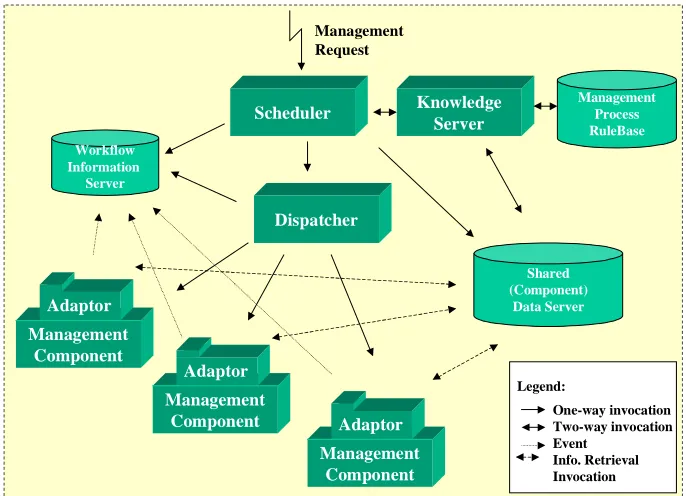
the Computer Science department of Trinity College Dublin. Figure 10 shows a
schema of the Serene WFMS architecture.
The engine consists of a scheduler that accepts management requests and initiates
instances of these requests and quizzes a knowledge base to know which activity
should be started. Once the activity to be started has been decided upon then the
information that it has been started is stored in the Workflow Information Server
(WIS). Then the scheduler passes the information to the dispatcher, i.e. the
information that the activity has been started. The dispatcher then invokes the
Figure 10: The Serene Architecture
The management component adaptors interface the workflow engine to the
components [Wade99]. Between the adaptor and the workflow engine only workflow
data is transferred. The data that is needed for an activity to be completed is stored in
the Shared Component Data Server (SCDS), which has been renamed the Shared Data
Exchange (SDE). It is the job of the adaptor to retrieve this information from the SDE.
It is also up-to the adaptor to store any resulting output parameters from an activity in
the SDE. The SDE is the focus of research that was carried out for this project. The
SDE comes under the problem statement as described in section 1.2. It is the adaptor
that lets the workflow engine know that the activity has finished by notifying the WIS.
The scheduler, dispatcher and adaptors were all implemented in Java running on
Windows NT. The WIS and Management Rulebase use commercial database and
Knowledge based systems. CORBA (OrbixWeb) was used as the distributed platform
for the workflow engine [Wade99]. The workflow engine is event driven and also
multithreaded.
2.6.1 Knowledge Server
The Knowledge Server supports the representation of management business processes
via a rules base, known as the Management Process Rulebase [Wade99]. A unique ID
is assigned to every business process instance and then an activity instance is assigned
its own ID as well. The rulebase that is used is the Java Expert System Shell (JESS).
A business process object is created, and it is the scheduler that interacts with this
object.
2.6.2 Scheduling Management Activities
The scheduler ensures the flow of information and controlled interaction between the
management activities, in order to accomplish the desired management process. There
are three operations that the scheduler supports: start, query, and abort a management
process. As this component is multithreaded it can allow multiple management
processes to run concurrently.
2.6.3 Workflow Information Server
This server is used by the dispatcher, and scheduler. It is possible to view which
management processes are currently running, and the state of the management
activities. The data that the WIS uses is stored in a Process Warehouse that the WIS
can query. All queries are done using SQL. The data that is stored in the process
warehouse is shared and therefore there exists locking methods to prevent
inconsistency in the data. Four states exist for a management activity: inactive, active,
complete, and abort.
The dispatcher is invoked by the scheduler. The dispatcher’s objective is to invoke the
component application that can complete a management activity. This invocation of a
component application is done by creating an adaptor. The dispatcher knows which
adaptors have been created. In allowing the dispatcher to create an adaptor rather than
allowing it directly to invoke an application, the dispatcher has less load on it. This
results in the dispatcher being able to take on more requests from the scheduler.
2.6.5 Component Adaptors
The adaptor is responsible for invoking the component application so that an activity
can be carried out. This is as discussed in section 2.4 above, i.e. to take some of the
load away from the dispatcher. It is the responsibility of the adaptor to access the SDE
so that it can pass any of the input parameters to the component application. It is also
one of the functions of the adaptor to store the output parameters of a completed
activity in the SDE. The adpator starts a thread, which then binds to a wrapper. Each
component application is started using a specific thread that has bound to a wrapper,
i.e. each thread is specific to each component application. Input parameters, and
output parameters are retrieved and stored respectively by the wrapper.
2.6.6. Shared Component Data Server/SDE
In version 1 the components wrote to files, which were then read by the components.
This data relates to the data that is needed for an activity rather than the control data
than is needed to allow effective flow control of a management process, or processes.
Therefore there was limited functionality.
As stated in section 1.2 the objective is to investigate the issues and propose a
solution(s) to support information flow between components in an engine based
workflow environment. This means that the SDE must be developed to prove the
hypothesis of this project. The functionality of the SDE must be extended with respect
to the method of storing and retrieving of data in this second version of the Serene
2.7 Data Integration
The core of this dissertation is to make available a data store in which the components
involved in the WFMS can store and retrieve their outputs and inputs respectively.
The details will be discussed in the Design section (Chapter 4). Data integration
entails supplying the workflow engine with access to a Database Management System
that allows persistent storage of the outputs of activities in a business process. An
investigation into data exchange resulted in the analysis of the prototypes and their
methods of sharing data. These prototypes are those that were discussed in section 2.5.
It is necessary now to look at the various ways data is stored in general in a distributed
environment, not just specifically in relation to WFMS.
2.7.1 Data Integration of Prototypes
In the analysis of the WFMS prototypes, the consideration of the data flow and the
methods of storing and retrieving the data is an issue that is left separate to the
development of these WFMSs. In the prototypes investigated the data that was
focused on was the control data, i.e. the data that is used to decide whether an activity
in a business process has completed, and that the next that activity should be
activated. Production data, otherwise know as activity inputs, is not directly addressed
in all of the prototypes, and it is viewed as an orthogonal issue to the development of
WFMS.
To summarise the issues of data integration in the prototypes researched:
• ORBWork: The nature of the underlying persistence media is orthogonal
to the functionality of ORBWork [Das97]. The data that is needed for an
activity is passed from it’s preceding activity and then unpacked. The
output is then stored and this is done by a method called ‘Save’, and this is
implemented using an external persistency storage mechanism (such as an
Object Oriented Database [Das97]), or the persistent object services of
• Mentor: The data flow is examined using activity charts which are
directed graphs, where the data items are shown as the arc annotations. The
invoked applications query the databases that store the data that an activity
needs to complete its task. Therefore the storage mechanisms are already
set up. There are also separate databases that can be accessed depending on
the activity.
• Mentor-Lite: The data flow in this project is seen as orthogonal to the
control flow handling. The system has been built with a view to stepwise
integration with already existing applications, and so the data flow
solutions that already exist are used. The invoked applications already have
a mechanism to store and retrieve data, so it is these methods that are used
to carry out the data exchange.
• Panta Rhei: The WFMS is connected to a database, and the API JDBC is
used to connect to the database. The data that is needed to carry out a
business process is stored in the database, along with all other data that is
necessary for the WFMS to render a business process complete.
• Serene Version 1: There exists a Shared (Component) Data Server which
makes use of serialising the objects that an activity needs for completion.
These objects that contain the input data for an activity are serialised to a
file. This was seen to be a temporary procedure for version 1 development,
and functioned well, but it was viewed that the SDE could be developed
with more functionality and intelligence.
• Exotica/FMQM with Lotus Notes: As described IN detail in section 2.5.4
the management of the data flow is done using Lotus Notes. The data flow
is separated from the control flow, i.e. the workflow engine, and so the
data flow is better managed, leaving the workflow engine to focus more on
the scheduling of activities. The data is passed from one activity to the next
by replication. This is why Lotus Notes had been used because of its
replication capabilities.
Overall there is less importance given to production data flow. The Serene Workflow
engine is, among the above prototypes, the only one that specifically states the need
process’ activities, and their related inputs. The Exotica/FMQM is the only research
project that set out to focus on how data flow should be managed in a distributed
workflow environment, and its conclusion was that two products should be used, one
for the workflow engine, and another to handle the data flow.
2.7.2 Data Integration Options
There are three main ways to integrating data in a distributed environment:
• One central computer that collects and processes all data
• Independent computer systems in each office/region that do not share data
with the other offices/regions
• A distributed database system
2.7.2.1 Centralised Database, Distributed Access
A centralised database is one that is located on one machine or server and is accessed
by clients across a distributed system. This improves data integrity, but there are
problems associated with a centralised database. The database can become a
bottle-neck if there is a high amount of traffic to and from the centralised database. If
however the centralised database can handle the traffic then it can be considered an
appropriate solution vis-à-vis the other two solutions detailed below. Data integrity is
improved due to the fact that the data is stored in only one place and only once. There
is no replication, or partitioning of the data. This allows for easier management of the
2.7.2.2 Partitioned Databases
The second option is partitioning the database, but this implementation is only
possible when there is no sharing of data across the partitions that have been set up.
These partitions are generally based on office locations, or regions. It is common to
still see this approach in organisations around the world. Any sharing of data is
usually transferred by e-mail, or faxes. This is an ineffective procedure if there are no
well-defined boundaries in the data, and if there is need to share data across
boundaries
2.7.2.3 Distributed Databases
A distributed database is the third option available and this has significant advantages
over the other two approaches. One of the major advantages, which is one of the
objectives of distributed systems, is that a distributed database system is extensible. A
distributed database system is one where most updates and queries are accomplished
locally, but anyone in the organisation can access the information stored in any of the
distributed databases if they have authority to retrieve and integrate the data. Control
over the data is retained locally. One of the major strategies of designing and
controlling distributed databases, is to replicate data. This form of database uses an
approach that is better suited to the layout of a company, given that most large
organisations have different departments, offices, or can be in different regions.
Backup and recovery plans are substantially more important when designing a
distributed database system. A well-designed distributed database should give the
users of the system location transparency.
One approach to distributed databases applications is the use of the Three-Tier
Client/Server Model. The three-tier approach adds a layer between the clients and the
servers. The three-tier approach is particularly useful for systems having several
database servers with many different applications [Pos99]. This use of middleware
allows an application to make use of legacy applications. Another advantage of the
need not know. This approach is well suited to object oriented development. Much of
this object oriented approach is discussed in the next section.
2.8 Enabling Distributed Object Technology
As described in the introduction (Section 1.1) there is a move in the software world
towards componentisation which allows software reuse, and enables organisations
build on to existing applications, therefore avoiding the need to develop systems from
scratch. There are various standards that have been developed to enable distributed
computing such as Distributed Transaction Processing (DTP) defined by X/Open, the
Distributed Computing Environment (DCE) defined by the OSF, CORBA defined by
the OMG, and DCOM defined by Microsoft.
Component based reuse is seen as an increasingly important software development
aid. This allows for the building of systems using components that can interact
through well defined interfaces, and can offer a route to reusing software across
projects. Two component emergent technologies are addressing component design
and development, OMG’s CORBA Component Model, and Enterprise JavaBeans.
These will be outlined later in this section. It is envisioned that these technologies will
not be used in the development of the SDE, but their evaluation is important so as to
be able to make recommendations with respect to the Serene workflow engine.
2.8.1 The Component Model
A definition of the Component Model is as follows:
• A component model defines the basic architecture of a component, specifying the
structure of its interfaces and the mechanisms by which it interacts with its
container and with other components. The component model provides guidelines
to create and implement components that can work together to form a larger
application. Application builders can combine components from different
The component model is aimed to have a multitier distributed application architecture.
A multitier application is one that has been split into multiple application components.
This results in having significant advantages over the traditional client/server
architectures including improvements in scalability, performance, reliability,
manageability, reusability, and flexibility.
In designing components one is allowing the use of reusable software, which is the
primary objective of componentisation. A component has it’s own interface which is
published and so is available to any other component or client in the system. This
interface once defined should not be changed, allowing the clients or other
components in a system to know what the functions of the component are and the
results that they return. This gives them the added advantage of not needing to know
or understand how the component carries out any of its functions. It also sets a
standard, so that if it is necessary to use a component the developer will know what
the component is, and how to reuse it, that is if the developer is familiar with this
particular component. Otherwise there would be additional information on what the
component is, and what it does. An organisation involved in component technology
would have some form of repository, a kind of reference, that would hold details on
all the components that it has. This repository would be invaluable for software reuse.
Development of applications would be able to reuse previously developed
components, therefore saving valuable hours in development time, as it would be
simply a task of putting the necessary components that already exist, together.
2.8.2 Workflow and the Component Model
There is a development in workflow that workflow tools could provide a vital element
in the co-ordination of distributed components within different domains. In a WFMS
new components can be added to provide the necessary functions of new business
processes and their related activities. Component integration is therefore an area of
importance for WFMS. This integration of components has some key requirements:
• Ability for components to interoperate even if they have been implemented
using different programming techniques.
• Ability for components to interoperate even when they offer interfaces that
have been defined in different languages, e.g. IDL, ODL, GDMO or SMI.
• An integration mechanism that minimises the knowledge needed of other potential interoperating components when a new component is developed.
• The need for an integration mechanism that clearly supports the needs of
specific business processes in a clearly observable manner.
• The need for an integration mechanism that is robust to changes in technology.
• The need for an integration mechanism that minimises the obstacles to
adapting a component to a new application.
2.8.3 The CORBA Component Model
The CORBA Component model is part of the CORBA 3.0 specification. This has got
much media coverage within the IT world which has yet to be released. The main
extension to the CORBA 3.0 specification is the addition of the CORBA Component
Model. This component model specifies a framework for the creation of plug-and-play
CORBA objects. The integration of Enterprise JavaBeans is also an integral part of
the component model, and the model will also help in the further integration of other
object-based technologies. Enterprise JavaBeans (EJBs) will be discussed further in
section 2.8.4.
The model is based on EJBs, but it extends the power of CORBA, in that this
component model is intended to work with the other major programming languages
such as C++, COBOL, Smalltalk, and ADA. This gives increased power to an
organisation that has legacy systems developed that are still extremely useful to the
organisation, and therefore avoids the need to redevelop these systems, saving time
and money, which is of great importance to an organisation. These legacy systems can
now be exposed to the developers within an organisation, thereby creating one of the
The Component Model expresses the component as a type in CORBA IDL. The type
definition provides both compile-time and run-time information on its external
interfaces. This includes new IDL syntax to provide:
• Unique component identification
• Identification of interfaces that the components both provides and uses
• Details on the events that a component both emits and consumes
• Navigation interfaces that allow the above to examined
• Interfaces that allow runtime attribute and property configuration
• Interfaces for managing multiple component instances
2.8.4 Enterprise JavaBeans
The Enterprise JavaBeans (EJB) component model logically extends the JavaBeans
component model to support server components. Server components are reusable,
pre-packaged pieces of application functionality that are designed to run in an application
server [EJB98].
The main advantage that EJB has over the other component models is that it manages
the middleware services for the components themselves, and as a result removes some
of the development from the application developer. There is no need for the developer
to be concerned with services such as lifecycle, state management, security,
transactions, and persistence. The EJB model manages these services. Application
development is therefore speeded up, as the developer does not have to waste time on
the complex middleware. The EJB model is very versatile and is able to integrate and
interoperate with environments that are compliant with the EJB model. This
A container is where the components execute and this container manages the
components. In practical terms a container provides an operating system process or
3. Requirements
The development of a prototype for this dissertation was implemented in conjunction
with the development of the Serene Workflow Engine Version 2. The architecture of
this version is as described in section 2.6. The requirements that were stated at the
outset of the project were therefore requirements that were essential for the integration
of the Shared Data Exchange (SDE) with the Serene Workflow Engine. Initially the
investigation into data exchange in a componentised workflow environment focused
on the prototypes that have already been developed, and then a prototype data
exchange server was developed.
3.1
General Requirements for Integration of Data
Analysis of Data Flow
For any integration of a data store the initial step is the analysis of the actual data
flow. This entails identifying activities, and then the input data they use and the output
data that the activity produces. There are various methods for accomplishing this, and
the best form of analysis is a diagrammatic representation of the data flow which the
experts, that are familiar with the activities and flow of data in a system, can render
comprehensible to the developer. A data flow diagram shows how activities depend
on one another for their information. From the data flow a data model can then be
designed. The objective is that the data store should always be consistent with the data
model. It is essential that this be done correctly as an incorrect data model will make it
more difficult to rectify later on during the development of an application.
Integrating the Application
The limitations of a data store must also be acknowledged. The objective of a data
store is to supply applications with a mode of storing data and retrieving data. There is
only a certain amount of intelligence that can be built into the data store, and this
middleware is being used to develop an application to allow for the retrieval and
storage of data, then there can be intelligence built into the application code that
separates the middleware from the Database Management System (DBMS). The
DBMS itself is limited in its functionality in providing intelligence. Intelligence can
be defined as the manipulation of the data so that it can be returned to the requestor in
the format, or type, that the requestor might need it in, and also the storage
requirement might mean that the data would need to be manipulated in some way so
as to make storage possible. One of the reasons for the necessity of such requirements
is brought about by the use of object-oriented languages, and the DBMS that are also
used in the integration. They might not be interoperable and some manipulation might
be essential to make the applications work together.
Need to be Able to Store Outputs, Retrieve Inputs and Retrieve Outputs
The major and defining requirement of Data Integration is to be able to store data and
then retrieve then data when necessary.
Provide SDE with Application Code for Storing and Retrieving Data
One of the requirements is to provide a server that implements the above requirements
of storing and retrieving data. This is to act as a bridge between the chosen DBMS and
the components that invoke the methods to store and retrieve data. This
implementation should be opaque to the components that call it, that is to say there is
no necessity that the components see the implementation code, or understand how it
carries out the storing and retrieving of data. All they require is that the
implementation works.
Provide Interface to the SDE
This follows on from the above requirement. The components will only see an
interface that will allow it to call methods for storing and retrieving. The requirements
for the interface will be discussed further in section 3.2.
Provide a Means of Preventing Concurrency Problems
In a distributed environment occasions arise when two users might try and update the
the data integrity. This must be avoided so that any updates, or storage, or retrieval of
the data must include a blocking function so that only one update occurs at a time.
Avoiding Deadlock in a Distributed Database
Deadlock must be avoided at all cost. Deadlock occurs when a user could hold a lock
on a table on one computer, and be waiting for a resource on a different computer.
Another user could be waiting for the resource that the first user has locked, and they
themselves have locked the resource that the first user is waiting for. The second user
is unable to release until the first releases. The deadlock problems have to be
identified so that they can be avoided.
Hardware Requirements
The platform that the data integration is going to be carried out on must be taken into
account. The DBMS should be chosen depending on the platform used.
3.2 Data Integration in the Serene Architecture
The Serene architecture has already been described in section 2.6. At the outset of the
project there were specific requirements that were given to allow the integration of a
Shared Data Exchange (SDE), which were important to adhere to, as the integration of
the SDE would have been all the more difficult if these requirements had not been
followed.
Hardware Requirements
The application is to be built on the Windows NT platform, as the Serene workflow
IDL to Provide the Interface to the Server
The first step in the development is to design an IDL interface so that the other
components would know the interface to use in order that they could implement the
storing and retrieving functions of the SDE. This interface allows the implementation
of the SDE to remain opaque to the components of the workflow engine
Store the Output of an Activity
When an activity is completed in a business process there are generally outputs, and
these outputs should be stored in some form of data store. This is one of the major
requirements, as the project is based on data exchange, so a mode of storing was
important to achieve the goal of data exchange.
Retrieve the Input of an Activity
An activity in general needs some parameters so as to complete, so there was a
prerequisite that there be some method in the interface to be able to retrieve the inputs
of an activity.
Retrieve the Output of an Activity
On occasion it is necessary to retrieve the output of an activity that has previously
been stored and it was requested that there be an interface that reflected this.
Data Flow Model
In order to gain a better understanding of the data in the business process under
examination, a data flow model would have to be extracted. This involves sitting with
the people who understand the data and can then provide expertise on the data in the
system that will be stored, and retrieved. The data flow model is therefore to be
implemented in the chosen DBMS. This data flow model should reflect the data store
limitations, and aid in the storage and retrieval of data.
Develop the Interface Using Orbixweb
As the middleware used in the Serene workflow engine is OrbixWeb, which is based
on the CORBA standard, the IDL’s produced must be compiled using OrbixWeb, and
CORBA standard. The CORBA specification used in this project is 2.3. All coding on
the server side has to take into account that OrbixWeb is the middleware.
Provide DBMS
The DBMS that is to be used is Microsoft Access 97. This requirement was specified
at the outset of the project.
Provide SDE that Implements Store and Retrieve Methods
The server that is to be developed must provide the implementation of the methods
described in the interface. These methods are the three that are described above, i.e.
store output, retrieve inputs, and retrieve outputs. The implementation of these
functions should not concern the components that invoke them.
Need to be able to Return the Inputs as Required by an Activity
The inputs of an activity may have to be built on the server side so that they are
compatible with the required input of an activity. This may require hand-coding the
retrieved inputs of an activity. This should also be opaque to the components that
invoke the methods defined in the interface.
3.3 Different Approaches to Data Integration
3.3.1 File Based Storage Approach
The SCDS of version 1 of the Serene workflow engine allowed components to invoke
methods on a server implementation class that stored and retrieved data. This server
was called the Shared Application Data (SAD) Server. The function of this was
limited to storing only objects that were serialisable. The objects that were stored and
retrieved were CORBA objects of type ‘Any’, which is a class defined in CORBA and
also in the API’s of Java. These objects of type ‘Any’ allow any other type of object to
be packed into them. This allows for a generic mode of transferral from a component
to the data store. The objects themselves were serialised to a file by the SAD server,
The retrieval method that was invoked would read the serialised object from the file
where they were stored, and then the SAD server implementation class would
unserialise them, and pack them into the container type CORBA ‘Any’. The object of
type ‘Any’ would then be passed back to the component that invoked the method. The
component could then unpack the object and use the input to complete an activity.
The details of the type ‘Any’ will be examined in greater detail in the implementation
section.
One major requirement for this approach to data storage is that all objects that were to
be stored had to be serialisable. This meant that all the objects needed to implement
the serializable class defined in Java. This meant editing all the classes that defined
these objects. Another requirement for the SAD server to work meant that the objects
passed to the SAD server were to be of the type CORBA ‘Any’. The server had to
have the ability to accept CORBA objects, and also know what types were packed in
the ‘Any’.
3.3.2 DBMS Storage Approach
Once an activity in a business process has completed the data that it generates is
considered to be the output of the activity. There must exist some mechanism to allow
for this output to be stored persistently. Persistency storage, in this project, entailed
using a DBMS to provide this functionality. By providing persistent storage the
Serene workflow engine would be enabled with a data store that can be used in the
future for further querying and investigation. The obvious prerequisite of persistency
storage is that each output of an activity must be stored.
A component must be able to pass in an object to the server that is implementing the
storage function. This object will be a CORBA object of type ‘Any’. On storage of an
output the method that is invoked on the server side must avoid concurrency
problems, so that when one component is storing an output, no other component can
store an output of an activity to the DBMS. The DBMS that is used for persistent
each CORBA object. The CORBA objects that should be assigned the key are the
CORBA objects that contain the output of an activity.
3.3.3 Memory Cache Approach
A memory cache approach is an intermediate solution, between a transient data
solution and a persistent solution. The main requirements are similar to the
requirements in the above section, for the persistent DBMS storage approach. When a
call is made to the server that implements the storage functionality then the output of
an activity should be stored in the memory cache.
The memory cache must be able to store objects of type CORBA ‘Any’. These are the
types that are passed in from the components that wish to store the output of an
activity. The output of an activity is contained within the CORBA ‘Any’. These
objects must have an index, or key, that is unique for each activity.
3.3.4 Cache & DBMS Approach
The combination of the persistent storage approach, and the memory cache approach
is seen as beneficial to the development of data storage. It can increase the speed up
retrieval and have persistent storage of the data. If there are any problems with the
memory cache then the DBMS will always contain the data that is being searched for.
The DBMS is almost a backup to the memory cache. The storage of data occurs in
both the memory cache and the DBMS. If data is being retrieved and it is located in
4. Design
4.1 Overview
The overriding requirements for this project is that for each activity in a business
process it is possible to store the output of a completed activity, and an activity is also
able to retrieve its input so that it can complete its activity. An extra requirement that
developed during the project was that a component should be able to invoke a method
that would return the output of a completed activity that is stored in the data store.
The basic design is as shown in figure 11. As can be seen from the diagram a
component invokes the store interface on the server. The server then implements this
method and stores data to the database. Then for the retrieve method the component
invokes this method on the server. The server, as was done for the store method
[image:48.595.95.525.449.560.2]implements this method and retrieves data from the database.
Figure 11: Basic design of the SDE
In figure 12 a diagram of the data flow is shown. This data flow represents the flow of
data for the store function. It is the output of an activity that is being stored to the
database.
Retrieve Store
Retrieve Store
DataBase
Figure 12:Data flow of the Store Method
In figure 13 the data flow is shown for the retrieve method. There are two forms of the
retrieve method: 1) retrieve the input for an activity that a component is carrying out,
and 2) retrieve the output of an activity that has already been completed. It is
important here to distinguish between the two because t
![Figure 9: Co-ordination of distributed workflow and data management [Alon97a]](https://thumb-us.123doks.com/thumbv2/123dok_us/975932.611015/27.595.100.508.192.551/figure-ordination-distributed-workflow-data-management-alon-a.webp)