Hardware Reference Manual
Publication No. 8000129-01, Revision A
October 1984
Ramtek
2211 Lawson Laneinterference to radio communications. It has been tested and found to comply with the limits for a Class A computing device pursuant to subpart J of Part 15 of FCC Rules, which are designed to provide reasonable protection against such interference when operated in a commercial environment. Operation of this equipment in a residential area is likely to cause interference. The user, at his own expense, is required to take whatever measures may be required to correct the interference.
Ramtek Corporation has prepared this manual for use by Ramtek personnel, licensees, and customers. The information herein is proprietary and will not be reproduced in whole or in part without Ramtek's prior written approval.
Ramtek reserves the right to change, without notice, the specifications and materials herein. Moreover, Ramtek is not responsible for damages caused by erroneous information, including but not limited to erroneous typography, arithmetic, or listings.
CONTENTS
Paragraph Page
1.1 1.2 1.3 1.4 1.5 2.1 2.2 2.3 3.1 3.2 3.3 3.4 3.5 3.6 3.7 4.1 4.2 4.3
Chapter 1. GENERAL INFORMATION
·
.
·
.
. .
. · .
.
. .
INTRODUCTION • • • • • •
HOW TO USE THIS MANUAL •
·
.
.
. ·
.
. .
.
. .
1.2.1 Manual Organization • • • • • • • • • •
1.2.2 Conventions Used In This Manual • • • •
1.2.3 Reader Comment Form. • • • •
FCC REQUIREMENTS • • • • • • • • •
RAMTEK SERVICE • • • • • • • • • • •
·
. . .
·
.
.
·
.
. · .
·
. .
·
.
.
·
.
.
·
.
·
.
.
1.4.1 Field Engineering Support. • • • •
·
.
.
1.4.2 Software Support • • • • • • • •
· .
1.4.3 T r a i n i n g . . . • • • •
·
. .
1.4.4 Technical Documentation • • • • •
·
.
.
·
. · . .
. .
SAFETY • • • • • • • • • • • • • •
· .
· .
.
.
·
.
.
.
· . . .
1.5.11.5.2
Electrical Safety.
Fire Safety • • • • •
· . · . .
· . · .
.
Chapter 2. PHYSICAL DESCRIPTION
GENERAL DESCRIPTION.
·
.
.
.
MAJOR COMPONENTS • • •
2.2.1 PCB Assembly
·
.
.
.
.
·
.
. .
·
·
.
.
.
.
.
2.2.2 Switch Panel Assembly • • •2.2.3 Trackball Unit • • • •
· .
.
.
. · .
.
2.2.4 Cable Assemblies.
SPECIFICATIONS • • • • • • • • • • • •
·
.
· .
·
.
.
.
.
Chapter 3. INSTALLATION AND OPERATION
INTRODUCTION
·
· . · · · · · · · ·
RECEIVING.
·
· ·
·
·
· ·
·
•INSTALLATION
·
•·
·
·
•·
·
•·
CONFIGURATION.
·
·
OPERATION.
·
•· ·
•·
·
·
•·
·
·
· ·
CHECKOUT
.
· ·
•·
·
•·
·
·
•·
·
RESHIPPING •
·
· .
·
· · ·
•·
•·
· ·
Chapter 4. FUNCTIONAL DESCRIPTION
INTRODUCTION • • • • •
·
. .
.
GENERAL FUNCTIONAL DESCRIPTION • • DETAILED FUNCTIONAL DESCRIPTION.4.3.1 CPU • • • •
·
.
.
4.3.2 EPROM 2G • • • • • • • • •
Paragraph 5.1 5.2 5.3 6.1 6.2 6.3 Table 2-1 2-2 2-3 2-4 3-1 3-2 5-1 6-1 4.3.3 4.3.4 4.3.5 4.3.6 4.3.7 4.3.8 4.3.9 4.3.10 4.3.11
Switch Logic • • • • • • Data Input Logic •• Shift Register IF •• Serial Output Logic •• Conversion Control Logic Decoder 20 • • • • • • •
Power-On Reset Circuit. Timing Logic • • • • Power Supply Circuit.
.
.
.
·
.
.
. .
· . . .
.
.
.
.
.
.
. .
. . .
. .
.
.
.
. .
.
.
. . .
· .
.
. .
.
.
. .
. .
· .
.
.
.
.
·
.
.
.
.
.
.
.
.
. . .
.
.
.
.
.
. . .
.
.
.
Chapter 5. MAINTENANCE
.
.
.
.
.
.
INTRODUCTION • • • • • PREVENTIVE MAINTENANCE • CORRECTIVE MAINTENANCE •
·
.
.
.
.
. .
·
.
. .
.
.
.
. .
.
.
. . .
.
. .
.
.
.
.
. . .
.
.
.
.
Chapter 6. PARTS LIST INTRODUCTION • • • • • • •
PARTS LISTS • • • • • • • ORDERING INFORMATION • •
.
.
.
.
.
. . .
. .
.
. .
. .
. .
.
. .
. .
.
.
.
. .
.
. .
.
.
. . .
.
.
. . .
.
Chapter 7. FOLDOUT ILLUSTRATIONS
Appendix. GLOSSARY
TABLES
Major Components. • • • • • • • • • • • • • • • • •
Connectors. • • • • • • • • • • • • • • • • • • • • • • • • • • • • Interface Cable Lengths • • • • • • • • • • • • • • • • • • • • • • Specifications. • • • • • •• • • • • • • • • • • • • • • • • • Interface Cable Connector Pin Functions • • • • • • • • • • • • • • Controls and Indicator. • • • • • • • • • • • • • • • • • • Fault Isolation Procedures • • • • • • • • • • • • • • • • • • • • • PCB Assembly Components • • • • • • • • • • • • • • • • • • •
Figure
2-1 2-2 2-3 3-1 F07-1
FIGURES
Trackball Controller • • • • • • • • • • • • Trackball Controller, Exploded View • • • • PCB Assembly, Component Side • • • • • • • • Controls and Indicator. • • • • • • •• Schematic Diagram • • • • • • • • • • • • •
· .
. . .
. . .
. .
.
·
.
. . .
.
.
.
.
. .
· . . .
.
.
.
.
. .
.
• • • • • • • • • • •
·
.
. .
. . . .
.
.
.
Page
1.1 INTRODUCTION
Chapter 1
GENERAL INFORMATION
This hardware reference manual provides the information necessary for a quali-fied technician to install, operate, and maintain the Ramtek trackball con-troller. Do not perform any maintenance if a maintenance agreement or war-ranty is in effect. Any maintenance performed could invalidate an agreement or warranty. If you need only user information without maintenance, read only chapters 1, 2, and 3.
1.2 IDf TO USE lHIS MANUAL.
The material in this manual is arranged in a logical sequence that anticipates reader needs. If you go directly to desired information, you may find you need additional information previously given.
1.2.1 Manual Organization
This manual contains the following chapters and appendix:
~ Chapter 1. GENERAL INFORMATION - Introductory information, FCC require-ments, Ramtek service, and safety information.
~ Chapter 2. PHYSICAL DESCRIPTION - A physical description of the trackball controller and list of specifications.
~ Chapter 3. INSTALLATION AND OPERATION - Receiving, installation, and operating instructions, checkout procedures, and reshipping instructions.
~ Chapter 4. FUNCTIONAL DESCRIPTION - A functional description of the con-troller.
~ Chapter 5. MAINTENANCE - Preventive and corrective maintenance procedures.
~ Chapter 6. PARTS LIST - A parts list and ordering procedures.
~ Chapter 7. FOLDOUT ILLUSTRATIONS - Illustrations larger than one page.
~ Appendix. GLOSSARY - A glossary of terms used in this manual.
1.2.2 Conventions Used In This Manual
1.2.3 Reader eo.ment Fo~
A reader comment form is provided for user feedback. Please enter any com-ments, suggestions, or complaints on the form. Include page, paragraph, fig-ure, or table number as applicable. The reader comment form is at the back of the manual.
1.3 FCC REQUIREJENTS
The trackball controller complies with FCC requirements for a Class A comput-ing device when installed and operated as directed in this manual. To minim-ize radio-frequency (RF) interference, tighten the screws that fasten all con-nectors. Do this during installation and any time you remove and reinsert connectors.
Observe the following precautions when installing and operating the trackball controller:
1. Operate the controller in accordance with the instructions in this manual.
2. Make sure the controller is always operated with the factory-installed cover securely fastened.
3. All modifications to the controller must comply with specified limits of the FCC rules.
4. Properly maintain the controller.
5. Make sure that all cables are shielded and shields are connected to chassis ground at both cable ends.
1.4 RAMTEK SERVICE
Ramtek customer service includes field service, software support, and sales support for supplies, accessories, and add-on components. In addition, we have a well-staffed training organization that fully qualifies customer per-sonnel to operate, maintain, and program Ramtek products. Technical documen-tation support includes all aspects of hardware and software.
1.4.1 Field Engineering Support
Ramtek maintains a complete Field Engineering Department that provides on-site service, depot repair facilities, and a full staff of technical specialists. For special situations or problems that cannot be resolved by our field offices, Ramtek specialists are available for phone conSUltation or for on-site consultation, if necessary.
but also upgrade the 90-day factory warranty to on-site. On-site service is also available on a time and material basis.
We maintain a full service depot for repair or exchange of parts during or
after the warranty period. Obtain prior approval and a return material
authorization (RMA) number before returning any merchandise. Parts must be shipped prepaid.
For additional information regarding service offered by our Field Engineering Department, call your local Ramtek office or call Field Engineering at (408) 988-2211.
1.4.2 Software Support
Ramtek offers a unique software support department staffed with highly
quali-fied analysts to assist users. For prompt software support, direct all
inquires to your local sales representative.
1.4.3 Training
The Education Department at Ramtek headquarters in Santa Clara, California, conducts regularly scheduled hardware and software training classes. In some circumstances we give on-site training.
1.4.4 Technical Documentation
Ramtek Technical Publications staff write and produce hardware and software documentation to support Ramtek products. To receive prompt documentation support, direct all inquiries to your sales representative.
1.5 SAFETY
Only qualified maintenance technicians should service or adjust internal com-ponents.
1.5.1 Electrical Safety
Careless handling could result in damage to electrical components. Be careful when servicing equipment with power applied.
1.5.2 Fire Safety
To obtain a copy of this standard, write to:
National Fire Protection Association 470 Atlantic Avenue
Boston, Massachusetts 02210
Chapter 2
PHYSICAL DESmIPTION
2.1 GENERAL DESmIPTION
The trackball controller is an interactive peripheral device that is used with Ramtek colorgraphic display equipment, from which the controller normally receives +12 volt operating power. If the display equipment does not supply power, a jack on the controller can accept power from an AP01 power supply, part number 510350-01, which is available as an option.
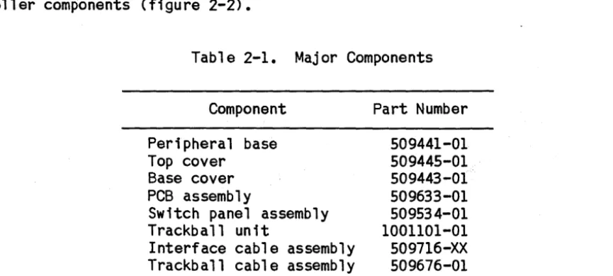
The trackball controller (figure 2-1) has a trackball and four switches that can control a cursor on a cathode ray tube (CRT) screen. The trackball can be manually rotated to move the cursor in any direction. The switches can turn the cursor on a~d off, make the cursor blink, and send data to a host computer to indicate trackball movement and switch status.
2.2 MAJOR aIFONENTS
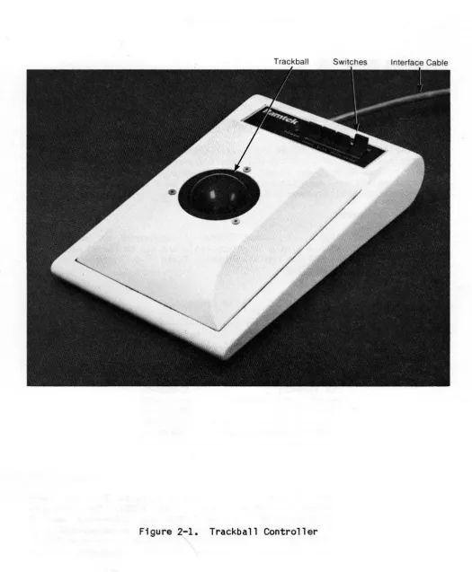
The trackball controller (part number 509440-01) connects to colorgraphic display equipment with a single interface cable and can be positioned on any level surface near the CRT for convenient use. Table 2-1 lists major con-troller components (figure 2-2).
2.2.1 PCB Assa.bly
Table 2-1. Major Components
Component Part Number
Peripheral base Top cover
Base cover PCB assembly
Switch panel assembly Trackball unit
Interface cable assembly Trackball cable assembly
509441-01 509445-01 509443-01 509633-01 509534-01 1001101-01 509716-XX 509676-01
[image:12.624.95.528.392.586.2]Trackball Switches Interface Cable
[image:13.612.37.562.89.726.2]Top Cover
TO J3
~P1
,
~,"
... ce ..~cable
Assembly
PCB Assembly
X0129-003-01A
A B c
1
Baud Rate 2
B~~~.. ~
[I-
.~[I
Select - ... i i - -.... ~:~g:: f(l.T ermma s . I 1920oe. 9 6 0 0 . . . ~: ~
•
rn
..03
: : R3
f1f1
:p
J2
.
ro
1Il
-o
•
•
•
•
•
•
•
•
•
•
•
~....;;;;;..---,.
11;:~JJi~ 1~[I~~
••
yy
-Z • • 1 - • • £:]t Cl
~1----J3
J4
Mode Select Terminals
•
\JQ_
-.00
J1
~
11
-~ ~6 61~J4
tj
VRIJ 1 - - - i i - - - - . ;
X0129-004-01A
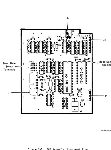
[image:15.634.62.537.67.707.2]'identified by number, and columns by letter. Coordinate designations are referenced in text and appear on the schematic diagram. The PCB assembly has four connectors. Table 2-2 shows connector functions.
Table 2-2. Connectors
Connector Function
J1 Connects to trackball unit
J2 Connects to alternate +12 volt power source
J3 Connects to switch panel
J4 Connects to display equipment
2.2.2 Switch Panel Asse.bly
This assembly consists of four paddle switches and a light-emitting diode (LED) mounted on a panel, plus a cable assembly. Three switches are two-position; the fourth switch is momentary. The cable assembly connects the panel-mounted components to connector J3, which plugs into J3 on the PCB assembly.
2.2.3 Trackball Unit
The trackball unit consists of a trackball in a metal housing. The trackball protrudes above the housing and can be rotated by hand in any direction. A connector is mounted on the side of the housing.
2.2.4 Cable Asse.blies
Trackball cable assembly connector PI plugs into the trackball unit, and J2 mates with J2 on the PCB. Interface cable connector PI plugs into the display equipment, and J4 mates with J4 on the PCB. The interface cable is available in four lengths (table 2-3).
Table 2-3. Interface Cable Lengths
Length in Feet Part Number
10 509716-01
25 509716-02
50 509716-03
[image:16.631.125.505.133.245.2] [image:16.631.125.483.556.641.2]2.3 SPECIFICATIONS
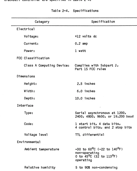
Electrical, physical, functional, and environmental characteristics of the trackball controller are specified in table 2-4.
Table 2-4. Specifications
Category Specification
Electrical
Voltage: +12 volts dc
Current: 0.2 amp
Power: 1 watt
FCC Classification
Class A Computing Device: Complies with Subpart J, Part 15 FCC rules
Dimensions
Height:
Width:
Depth:
Interface
Type:
Code:
Voltage level
Environmental
Ambient temperature
Relative humidity
2.5 inches
6.0 inches
10.0 inches
Serial asynchronous at 1200, 2400, 4800, 9600, or 19,200 baud
1 start bit, 4 data bits,
4 control bits, and 2 stop bits
TTL differential
-30 to 60°C (-22 to 140oF) non-operating
o
to 450C (32 to 1130F)operating
[image:17.638.53.522.121.707.2]Chapter 3
INSTALLATION AND OPERATION
3.1 INlRODUCTION
This chapter contains receiving instructions, installation procedures, operat-ing instructions, checkout procedures, and reshippoperat-ing instructions.
3.2 REa:IVING
The trackball controller is carefully inspected and packed prior to shipment from the manufacturing facility. Unpack and inspect the controller as fol-lows:
1. Examine shipping carton for external damage before accepting delivery. If carton is damaged, unpack controller while shipping agent is present.
2. Carefully unseal carton and remove controller and packing material. Save packing material for possible future use.
3. Inspect controller for scratches, dents, or chipped paint, especially in any places where carton is punctured.
4. Look for screws loosened by vibration during shipment and tighten any loose screws.
5. Inspect interface cable connector PI for foreign material that may impair electrical contact with mating connector. Remove any foreign material with a soft brush and vacuum cleaner.
3.3 INSTALLATION
The trackball controller may be positioned on any level surface near the CRT screen. Proceed as follows:
1. Plug connector PI (table 3-1) into mating connector on display equipment. Verify that connector is securely seated to ensure good cable grounding and to minimize radio-frequency interference.
2. Tighten connector holding screws.
3.4 CONFIGURATION
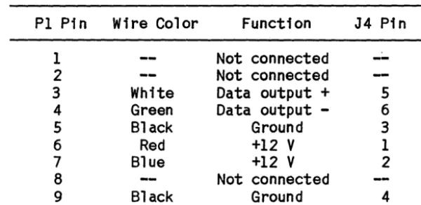
Tabl e 3-1. Interface Cable Connector Pin Functions
P1 Pin Wire Color Function J4 Pin
1 Not connected
--2 Not connected
3 White Data output + 5
4 Green Data output - 6
5 Black Ground 3
6 Red +12
V
17 Blue +12
V
28 Not connected
9 Black Ground 4
3.5 <FERATION
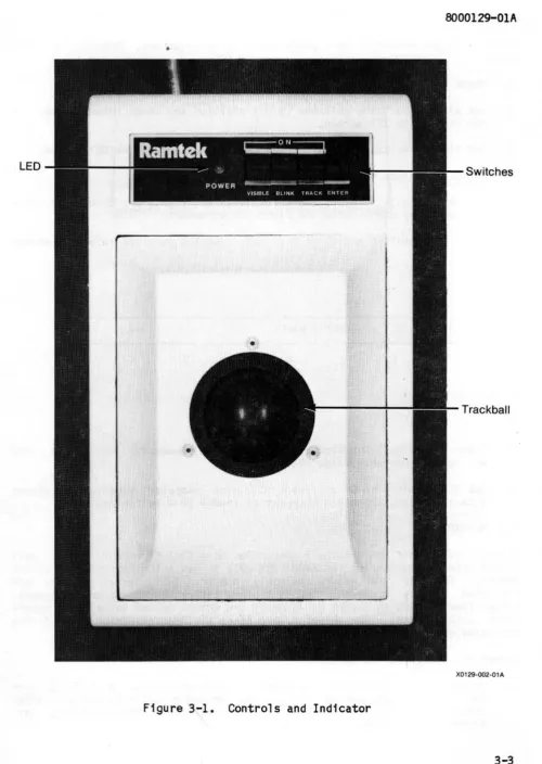
The trackball controller (figure 3-1) has four switches, a trackball, and an LED. Table 3-2 explains control and indicator operation.
Table 3-2. Controls and Indicator
Name Type Function
VISIBLE Two-position paddle switch Turns on cursor when set to ON
BLINK Two-position paddle switch Makes cursor blink when set to ON
TRACK Two-position paddle switch Sends a data byte to host computer after each trackball movement when set to ON
ENTER Momentary paddle switch Sends one data byte to host computer when pressed
Stops all operation when held in pressed position
Trackball Rotating ball Positions cursor on CRT screen when rotated
POWER Green LED indicator Lights when +12 volts of power are received
3.6 CHECKOOT
[image:19.629.143.443.100.246.2]•
LED
Switches
Trackball
X0129-002-01A
[image:20.612.63.563.34.738.2]checkout is not necessary when performance is satisfactory. Proceed as fol-lows:
1. Check that green POWER LED indicator is lit.
2. Set all two-position switches to off position and check that cursor is not visible on CRT screen.
3. Set VISIBLE switch to ON and check that cursor appears on CRT screen.
4. Set BLINK switch to ON and check that cursor blinks.
5. Rotate trackball forward, backward, left, and right~ and check that cur-sor moves up, down, left, and right~ in agreement.
6. Press ENTER switch and check that host computer receives following status byte:
VIS* BL*
TRK*
ENT*
-y +y+x
-x
7 6 5 4 3 2 1
o
X0129-005-01 A
7. Check that bits 0-3 reflect latest trackball movements. Check that bits 4-7 reflect current switch positions.
B. Set TRACK switch to ON and check that host computer receives a status byte after each trackball movement or change ina switch. position.
3.7 RESHIPPING
If you need to ship the trackball controller to a Ramtek repair depot~ call Ramtek Field Engineering at (40B) 988-2211 to get prior approval and an RMA number. Identify the owner, assembly number, full serial number, and requested service or repair on a tag and attach the tag to the equipment. Always identify the equipment by assembly and serial number in any correspon-dence with Ramtek. The serial number is on the identification label on the underside of the controller.
Repack the controller as follows:
2. Mark shipping carton "DELICATE INSTRUMENT" and "FRAGILE."
Chapter 4
FUNCTIONAL DES~IPTION
4.1 INTRODUCTION
This chapter gives a general description of trackball controller operation followed by functional descriptions of individual functional elements. Figure F07-1 (foldout in chapter 7}is a schematic diagram of the PCB assembly. In the schematic diagram, components are identified by individual designations such as Ql or VRI. lCs are identified by coordinate designations such as 2G or 3D. Where two or more components are packaged in a single IC, components are referenced by output pin number. For example, lA-9 and lA-5 are flip-flops with outputs connected to pins 9 and 5, respectively, of IC lA.
4.2 GENERAL FUNCTIONAl.. DES~IPTION
The trackball controller consists of three functional units:
~ Trackball unit
~ Switch panel assembly
~ PCB assembly
The trackball PCB assembly has a Zilog Z80l microprocessor that functions as a central processing unit (CPU) and controls PCB operation. CPU 2E receives cursor direction data from the trackball unit via connector Jl and control signals from the switch panel via J3. When the TRACK switch is set to ON, shift register IF converts parallel data from the CPU into serial data. Line driver 4E sends the serial data to the display equipment via J4 for transmis-sion to the host computer. Counter 2B clocks IF. Counter 3D controls each parallel-to-serial conversion. Erasable programmable read-only memory (EPROM) 2G stores program data for the CPU.
4.3 DETAILED FUNCTIONAL DES~IPTION
The PCB assembly consists of the following functional elements:
~ CPU 2E
~ EPROM 2G
Xl Switch logic
~ Data input logic Xl Shift register IF Xl Serial output logiC Xl Conversion control logic Xl Decoder 2D
Xl Power-on reset circuit Xl Timing logiC
4.3.1 CPU
The CPU controls PCB operation via the data, address, and control lines. Memory address outputs AO-1! and control output RO* go to EPROM 2G. Control outputs A12-14, MREU*, and RFSH* go to decoder 20. Data lines 00-7 are bidirectional. Signal RESET* from the power-on reset circuit resets the CPU at power on. A clock pulse from timing logic oscillator 3B synchronizes CPU operation.
4.3.2 EAROM 2G
EPROM 2G stores program data for the CPU. When signals ROMEN* and RO* go active, 2G transmits on lines 00-7 data stored in locations addressed by the CPU on lines AO-l1. Output data bytes go to the CPU.
4.3.3 Switch logic
Latch 1G receives switch status signals from the switch panel via J3. Signal QUAD* goes active to load the status signals into 1G. Outputs 04-7 go to the CPU.
4.3.4 Data Input logic
Signal RST* sets flip-flop 1A-9. Each time the trackball moves, a direction signal goes to the PCB via J1. A -Y signal clocks flip-flop lA-O, which resets. If QUAD* is active, lC-7 inverts the lA-9 output to become data bit 03. The +Y, +X, and -Y channels function in the same way. When the CPU is
ready to read direction data, QUAD* goes active. After the CPU reads the data, RST* goes a~tive, setting the flip-flops, which are then ready to detect another trackball movement.
4.3.5 Shift Register IF
Shift register IF converts parallel data from the CPU into serial data. Sig-nal SERIAL DATA LO* goes active to load parallel data on lines 00-7 into 1F. After SERIAL DATA LD* goes inactive, the clock pulse received at input C clocks the data out at output G.
4.3.6 Serial Output logic
Signal SERIAL DATA LO*, when active, resets flip-flop 2C-S and sets flip-flop 2C-8. This prevents data transmission to the host computer while 1F is being loaded. After SERIAL DATA LD* goes inactive, 2C-S transfers serial data from 1F to 2C-8, which inverts the data. Pulse BAUDCLK clocks both flip-flops. Transistor Ql drives differential line driver 4E-6, which sends the data to the display equipment.
4.3.7 Conversion Control logic
Counter 3D, therefore, controls the period of time l2F operates. After STA-TUSEN* goes active, inverter lC-13 inverts READY FLAG* to become data bit 01, which goes to the CPU. When STATUSEN* goes inactive, lC-13 goes to a
high-impedance state.
4.3.8 Decoder 2D
Decoder 20 generates five signals that control PCB operations. When signal MREQ* goes active and RFSH* goes inactive, 20 decodes bits A12-l4 to derive five control signals.
4.3.9 Power-on Reset Circuit
This circuit resets the CPU and counters 2B and 3D at power on. Gates El-4 and El-3 are Schmitt triggers. Pin 6 of El-4 is at ground potential when power is first applied. Therefore, signals RESET and RESET* go active. After capacitor C14 charges, pin 6 goes to +5 volts, and RESET and RESET* go inac-tive.
4.3.10 Timing Logic
Oscillator 3B generates the basic clock pulse that clocks the PUC and binary counter 2B. A jumper across one pair of the baud rate select terminals deter-mines the baud rate by selecting one of the counter outputs. The selected BAUDCLK pulse clocks flip-flops 2C-5 and 2C-8. When READY FLAG* is inactive, pulse BAUDCLK also clocks IF and counter 3D via IE-II and 4C-2.
4.3.11 Power Supply Ci~uit
Voltage regulator VRI receives +12 volt power from the display equipment via J4-l and J4-2 and supplies +5 volt regulated power to PCB components. When an
Chapter 5
MAINTENM<E
5.1 INTRODUCTION
This chapter explains how to service and maintain the trackball controller. Preventive and corrective maintenance procedures are given. After doing corrective maintenance, verify controller operation by performing the checkout procedures given in chapter 3. Do not perform any maintenance if a mainte-nance agreement or warranty is in effect, as this could invalidate such agree-ment or warranty.
CAUTION
Be careful not to cause a static discharge that may damage ICs when handling equipment. Always place one hand on a grounded conductor before touching a PCB.
5.2 PREVENTIVE MAINTENANCE
Preventive maintenance is limited to inspecting and cleaning the controller.
CAUTION
To prevent damage to equipment, disconnect the controller before inspecting or cleaning.
Use a soft brush and vacuum cleaner to remove dust. While cleaning, inspect for damage.
5.3 OORRECTIVE MAINTENANCE
CAUTION
To prevent damage to equipment# disconnect the controller before removing or replacing parts or making continuity checks.
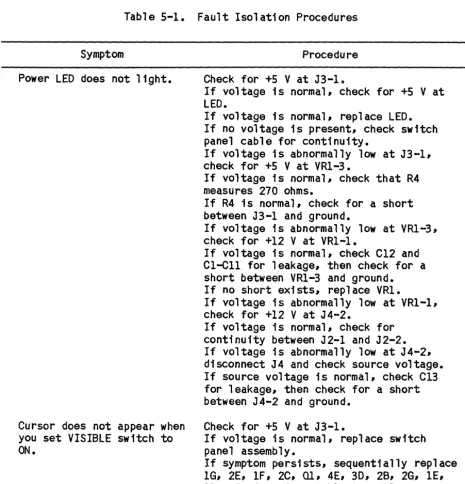
If a system problem occurs and you suspect a trackball controller fault# locate the symptom in table 5-1 and perform the suggested procedure. This table applies only to single-fault conditions.
Table 5-1.
Symptom
Power LED does not light.
Cursor does not appear when you set VISIBLE switch to
ON.
Fault Isolation Procedures
Procedure
Check for +5 V at J3-1.
If voltage is normal# check for +5 V at LED.
If voltage is normal# replace LED. If no voltage is present# check switch panel cable for continuity.
If voltage is abnormally low at J3-1# check for +5 V at VRl-3.
If voltage is normal# check that R4 measures 270 ohms.
If R4 is normal# check for a short between J3-1 and ground.
If voltage is abnormally low at VRl-3, check for +12 V at VR1-1.
If voltage is normal, check C12 and C1-C1l for leakage, then check for a short between VRl-3 and ground. If no short exists, replace VRl.
If voltage is abnormally low at VR1-1, check for +12 V at J4-2.
If voltage is normal, check for continuity between J2-l and J2-2. If voltage is abnormally low at J4-2, disconnect J4 and check source voltage. If source voltage is normal, check Cl3 for leakage# then check for a short between J4-2 and ground.
Check for +5 V at J3-l.
If voltage is normal, replace switch panel assembly.
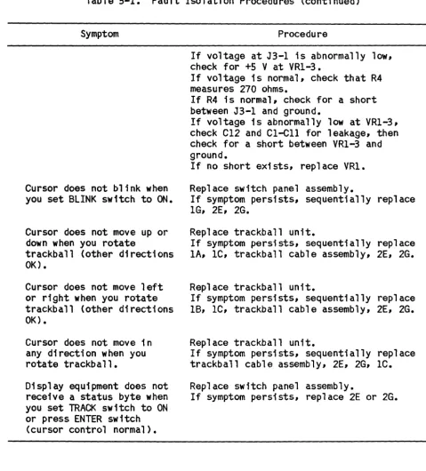
[image:27.631.69.534.236.719.2]Table 5-1. Fault Isolation Procedures (continued)
Symptom Procedure
Cursor does not blink when you set BLINK switch to ON.
Cursor does not move up or down when you rotate
trackball (other directions OK).
Cursor does not move left or right when you rotate trackball (other directions OK).
Cursor does not move in any direction when you rotate trackball.
Display equipment does not receive a status byte when you set TRACK switch to ON or press ENTER switch
(cursor control normal).
If voltage at J3-1 ;s abnormally low, check for +S V at VRl-3.
If voltage is normal, check that R4 measures 270 ohms.
If R4 is normal, check for a short between J3-1 and ground.
If voltage is abnormally low at VRl-3, check Cl2 and CI-Cll for leakage, then check for a short between VRl-3 and ground.
If no short exists, replace VR1.
Replace switch panel assembly.
If symptom persists, sequentially replace lG, 2E, 2G.
Replace trackball unit.
If symptom persists, sequentially replace lA, IC, trackball cable assembly, 2E, 2G.
Replace trackball unit.
If symptom persists, sequentially replace 18, IC, trackball cable assembly, 2E, 2G.
Replace trackball unit.
If symptom persists, sequentially replace trackball cable assembly, 2E, 2G, lC.
Replace switch panel assembly.
[image:28.632.64.543.77.607.2]Chapter 6
PARTS LIST
6.1 DNTRODUCTION
This chapter contains a parts list and ordering information.
6.2 PARTS LISTS
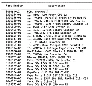
For a list of trackball controller components, refer to chapter 2. Table 6-1 lists PCB assembly components.
Table 6-1. PCB Assembly Components
Part Number Description
509634-01 1310154-01 1310146-01 1310150-01 1310148-01 1301309-00 1301493-00 1310149-01 1310153-01 1310147-01 1310152-01 1310151-01 1301374-00 9110008-01 1310155-01 3202201-00 3201122-00 3109103-00 3109102-00 3109123-00 6701104-02 6706016-00 6706336-00 8640162-01 3109271-00
PCB, Trackball
IC, 8300, Low Power CPU E2
IC, 74C165, Parallel 8-Bit Shift Reg F1 IC, 74C74, Dual D Flip-Flop C2, A1, B1 IC, 74Cl93, Sync 4-Bit Binary Counter D3 IC, Dual Diff Line Driver E4
IC, 4040, 12-Bit Binary Counter B2 IC, 74HC138, 3-8 Line Decoder D2
IC, EPROM, 27C64, 8192 x 8 BIT-300ns G2 IC, 4044B, Quad 3st NAND R/S Latch G1 IC, Tri-State Inverter C1
IC, 4093, Quad 2-Input NAND Schmitt El IC, 48MOS, + Voltage Regulator, B/T VRl Oscillator, CMOS Clock, 2.4576 MHz B3 IC, 74C04, Hex Inverter C4
Diode, 1N4454, SOY, 100MA CR1 Xstr, 2N2222, NPN, Switch/Amp Ql
Res, CC, 1/4W 5% 10K ohm R1 Res, CC, 1/4W 5% 1000 ohm R3 Res, CC, 1/4W 5% 12K ohm R2 Cap,Cer, .1UF SOV 20% C1-C11 Cap, Tant, 1.0UF 35V 10% C12, C1S
Cap, Tant, 33UF 20V 20%, Radial C13, C14 Jack, Pwr, 2.5mm J2
[image:29.627.122.494.300.647.2]6.3 ORDERING INFORMATION
Replacement parts are available from or through your local Ramtek office or representative. Include the following information when ordering components or parts:
~ Trackball controller serial number
~ Trackball controller assembly number
~ Part number (with two-digit dash number and revision level)
Chapter 7
FOLDOUT ILLUSTRATIONS
-tr;v
~
25
-~~URQ
~t.JUI ~WAIT
Jt.sv
~
veerE:lt-JD
~ _ _ _ _ M_R_~_0_' _ _ ~r---_ _ _ ~r---_ _ _ _ _ _ +-_ _ ~i~~ MReQ _ _ _ _ _ ~~~~~s~~ _ _ _ 1_---1_---_+---~~~O R~S~+'Sv
L,NT
zoo
c.PU 2E A14/ A13/ AI2./ AI4j--:4-_ _ _ -,..,...,/ AI31-"''--_ _ _ ../Alti-=1~ _ _ _ ../ All / AI' ~I _ _ _ _ --..::.:!l../
/
AIO 1-'4_0 _ _ _ _ _ 0/
M 3~
Ae ~g
/
/
/
A.., 1-"~..;..7 _ _ _ _ _ 0/
/ Ab 1-=3",-6 _ _ _ _ _ J
A; 3<;,
A", ~
A'!> 33
/ /
/
A.1. r-=3.=..2 _ _ _ _ _ _ . /
/
Aa!J
AI f--~-' - - - 0 /
A'/) 30
,
D7
D7~\3~---~~.//
10 /
Db C)
D51-',---../;
1)4 8 /
D3r,,'---//
Dz IS /
DI ~---./
eLK D~
14 DCli .)
12D
(ZN2ZZ.2)
t
ti
SV (74C\Q3) A \3q 1) "TCD;li
\0 !it\) I \ C. GlG~
~
B 3D 2 (lJ.(16 A Q~ ~ I
4 .3 I
_---1.<::1'1:> Q~~)
+.~5V ~ ''-Cl.:::'''---< J4-G.
~4E>
/..-L-5----< J4 - 5
(75153)
+'OVlicl71.>
lJ) M12. +'5V~2
----fr~
" 4E
10 0
"r
\4-~(~~)---~---t---+---~~~--~----~
7.AISto
M~Z
OSCILI>.TOR
RESET II Go GI GIl Q~ QA. Qo:, G6 13.7 Qe G:A Q\C Gil
~---__I,...-4 R
10 ~·~L---~---~_oc (4640'2)') SPARE DR.IVER X0129-006#1-01 A
[image:32.1238.164.1187.126.674.2]RPI 10K
5
~
~ 9
7
S
Y2- Ie..
I< ,0
1\ <;
14-R \
I'=' (.:
oe;
IS
~
'7e U 10
I
(4oq3~)32
J4
-I
>---1
POVJEJ2. VRI
A.!)APTE; 12 ";D(. K .
-i - I +V
3
I 7BC6
I j... 12
J4 - 2
+VN
~,j
J
I(E€:i+ CI3 '-ry
~,a.lF-
clzl
+sv~----.---j
lel.ell
O.I,,u~ I,uJ'---<" J 3 - I
J4'~ , . 6ND •• ~~D - - . . ---~~~~o
J4 - 4 ) - - - '
lo(74C.741 ~ \ (~8J!» D3
.-l.f. D S Ql-='q~ _ _ _ _ _ =.,G~ I Ie 'y),3L-_ _ _ _ _ _ _ ---"'/
~ 1/\ ~
~-_y~~_~~A _ _ _ ~---~I~1 c
,rl.-'.,- 12.
13
+5V
~D::pS~---~2~' ~~~3~---P-2--//
+YDA.'PI. 3
JI- -; /'>-.---+---~~c.12.
I
+5
10 ~
~ D '" GiI--''7~ _ _ _ _ _ _ '-''-lIO Ie
~ IB ~
J 1 -I ~>--+-')(....;.I)O;-;r:-A----_+---'-1 '-1>1 c 12. ,3
9 DI j
...9-±-
\I.:'~ (400..,eB)r
D S <llp5~ _ _ _ _ _ _ _ -'-l4 Ie ... SJI-11' -')(DA"lA
JI-7r--+5V JI-2.
JI -15 JI -4 JI -"
IE>
~ c R
I (74C74-)
+5V
:;PARE Al 4C.
74C04-Figure F07-1.
X0129-006#2-01 A
[image:33.1236.187.1152.116.739.2]Appendix
GLOSSARY
This glossary explains terms used in this manual. Ramtek hardware or software terms.
Some entries are unique
Baud rate: A measure of data flow equal to the number of signal elements transferred per second. -The size of the signal element varies from device to device. Baud rate equals bits per second (b/s) when each signal element is one bit.
B1t: <6inary digll) The smallest discrete information unit used in digital processing. A bit has a value of either 1 or O.
Byte: A string of bits treated as a unit during digital processing. Tra-ditionally, eight bits comprise a byte.
Coordinate: A value that specifies the location of any point in an n-dimensional matrix. For example, pixels in the Cartesian space of a monitor screen (a plane surface) are indexed by X and Y axis values that specify loca-tion in two dimensions relative to a common origin.
CPU: (Central processing unit) A specialized and dedicated digital logic
circuit that interprets and executes binary machine instructions. A CPU usu-ally contains several general-purpose registers, an arithmetic logic unit (ALU), one or more stack pointers, and an address counter.
CRT: (Cathode ray tube) An electronic vacuum tube with a phosphor screen that glows when excited by an electron beam. A rapidly modulated electron beam sweeps across the screen to produce a display.
Cursor: A position indicator that indicates where the next data character will appear or where the next read operation should occur on a CRT screen.
EAROM: (Erasable programmable read-only memory) A non-volatile read-only memory circuit programmed and erased with special equipment. EPROMS provide fast random access to frequently needed data and instructions.
Hexadec1mal: A number system with a base of 16.
IC: (Integrated circuit) A group of circuit elements inseparably
associ-ated on or within a continuous substrate.
LED: (Light-emitting diode) A semiconductor device that lights when
draw-ing current.
memory circuit programmable only once with special equipment. PROMs provide fast random access to frequently needed data and instructions.
Schmitt trigger: A circuit that changes state each time an input signal crosses a specified triggering level. A Schmitt trigger can produce a digital output from a slowly changing analog input.