Performance Analysis of FIR Filter Design Using
Vedic Multiplier with SQRT based Carry Select
Adder
Y. Bharath Kumar1,Dr. V.G. Siva Kumar2
1
PG Scholar, 2Associate Professor, Department of ECE(VLSISD) Vidya Jyothi Institute of Technology, Hyderabad, India
Abstract: In Digital signal processing, filters are used in all devices. Filters are used to extract a useful part from the input Signal and there required part of the signal is reached to the receiver. In this Paper, FIR filter has been designed using a Vedic multiplier and SQRT-CSLA (carry select adder). Combination of both Vedic multiplier and SQRT-CSLA (carry select adder) makes the FIR filter faster. For reducing the area of CSLA, it can be accomplished by using a single RCA and an add one circuit instead of using double RCA. The design of SQRT-CSLA by using RCA and BEC. The RTL synthesis using Xilinx 14.7 and simulations going to be done by using modelsim. The proposed design would be efficient in terms Of Speed and complexity. Keywords: Vedic Multiplier, SQRT-CSLA, FIR filter, Power, Delay, Area, Xilinx 14.7.
I. INTRODUCTION
Fig 1: FIR filter design with MCM and a 64-bit adder
Vedic Multiplier is based on ancient Indian Vedic Mathematics. Vedic mathematics contains 16 Sutras (formulae) mainly for the multiplication process. They all deal with various branches of mathematics like arithmetic, algebra, geometry, etc. Among all of the 16 Sutras, Urdhva-Tiryakbhyam is the most used method. Vertical and horizontal multiplication is carried out to reduce the partial product generation stages. The formula allows the parallel generation of partial products and eliminates unwanted multiplication steps. A reconfigurable Vedic multiplier has been selected which is a high-speed multiplier [6]. Vedic Multiplier is an efficient one compared to other multipliers like Array Multiplier, Booth Multiplier, etc. based on area, speed. Vedic Multiplier has one benefit that is the number of bits increases, area, and gate delay rises very slowly as compared to other multipliers. Finally, this reduced Vedic multiplier unit is applied into the transposed design of FIR filter to achieve the low area, delay, and low power. FIR filter also contains adder in the circuit to add the partial products during the multiplication process. An adder in the data path is required, which consumes less area and power with analogous speed. In Section-II presents a logic for Vedic Algorithm based multiplication operation. Section-III deals with the Comparison of Different types of multipliers. Section-IV Survey of CSLA Adders. Section–V deals with the Proposed Structure of Vedic Multiplier FIR filter design. Section–VI deals with the Synthesis results and comparison of different Multipliers using for FIR filter followed by Conclusion and References.
II. ALGORITHMFORVEDICMULTIPLICATON
For N x N multiplication, divide the multiplicand and multiplier into two parts, consisting of (N to N/2-1) bits and (N/2 to 1) bits. Among all the 16 sutras, the most and commonly used are only three for the multiplication purposes. Among the 16 methods (sutras), mostly general method is used for the multiplication process. The word Vedic is derived from the word Veda, which means storehouse of knowledge. The ‘Veda’ is a Sanskrit word and the word derived from the root word ‘Vid’. Meaning of this word ‘Vid’ is ‘know without limit’. Swami Bharati Krishna Tirtha (1884-1960), former Jagadguru Shankarachraya Maharaj culled a set of 16 Sutras and 13 Sub Sutras from Atharva Veda. Here the sutra means aphorism & sub sutra mean corollary. Among the four Vedas, Vedic mathematics is one of them. Actually, it is the part of Sthapatya Veda, which is aupa Veda of Atharva Veda [7].The Vedic mathematics is not a mathematical wonder but it is purely logical. All the formulas & sub formulas can be applied to geometry, trigonometry and differential integral calculus, applied mathematical problems. The advantage of Vedic mathematics is that, it reduces the complexity of conventional methods and turns into a simple method. All the formulas & sub formulas are based on natural principals like human brain. Therefore, this is a very interesting field in not only mathematics but in engineering also [8]. As can be seen in the figure 3 that adder is used in the intermediate addition, hence fast and area efficient design will enhance the overall performance of multiplication.
A. Urdhva-Tiryakbhyam Sutra
The word “Urdhva-Tiryakbhyam” meaning is vertical and crosswise multiplication. This formula is equally applicable to all cases of algorithm for N bit numbers. Usually this sutra is used for the multiplication of two numbers in number system and also applicable to binary number system. Advantage of using this type of multiplication method is that as the number of bits increases, delay and area increases very slowly as compared to other multiplication method. The number of operations that has to be performed is same as that in conventional multiplication method only thing is that delay.
X1 X2 x Y1 Y2 ---
X1Y2 X2Y2 X2Y2 X2Y1
--- S3 S2 S1 S0 Fig 2: Steps for 2x2 multiplication
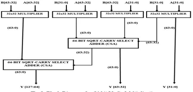
multiplication like add and shift. Therefore, it is time, power and area efficient [6]. In Fig 2, the digits on the both side of the line are multiplied and added with the carry of the earlier step. It generates one of the bits of the result and a carry. This carry is added to the next step multiplication result and hence the process goes on till end. If more than one line present in one-step, all the results are added to the carry of previous step. In each step, LSB (least significant bit) acts as the result bit and all other bits act as carry for the next step [5]. These partial products can be generated and added as per construction projected. The block diagram for 64x64 Multiplication based on Vedic technique as proposed in is shown in Fig 3. The first stage is four sets of 32x32 Multiplier, which is also based on Vedic technique.
Fig 3: Block Diagram for 64-bit Vedic Multiplication
Example: 564 x 474 ( 3 digit numbers)
Step 1: Step 2:
Step 3: Step 4:
Fig 4: Steps involved in the vertical and cross wise method
III.COMPARISONOFDIFFERENTTYPESOFMULTIPLIERS
A. Array Multiplier
An Array (cluster) multiplier is a parallel multiplier. Which moves and includes at the same time. It comprises of a variety of adders. Exhibit multiplier utilizes moves and includes activity as in two-fold multiplier however it includes the fractional items parallel. The every incomplete item is produced by the multiplicand and multiplier. It creates progressively halfway items, so it takes additional time, more region to get the last items.
B. Radix-4 Booth Multiplier
The Radix-4 Booth multiplier is a parallel multiplier. It is utilized to build the speed of the augmentation and it can decrease the halfway items .The Radix-4 Booth calculation is utilized to expand the speed of the multiplier and diminishes the territory of the multiplier. One of the arrangements of acknowledging rapid multipliers is to upgrade parallelism which diminishes the number of ensuing computation stages. The main idea is that as a substitute of adding and shifting of every column of multiplier term and multiplying with 1 or 0, we only take every next 2nd column, and multiply by ±1, ±2, or 0, to obtain the same results. Radix-4 booth encoder performs the process of encoding the multiplicand based on multiplier bits. It will compare 3 bits at a time with overlapping technique. Grouping starts from the Lower bit (LSB), and the first block only uses two bits of the multiplier and assumes a zero for the third bit as shown by figure 5.
Figure 5: 3 Bit combination as per booth recoding.
Process For Radix-4 Booth Multiplier
1) Extend the sign piece 1 position if important to guarantee that n is even.
2) Assign 0 to one side of the least critical piece of the stall multiplier.
3) According to the estimation of every vector, every fractional item will be 0, +1, - 1, +2 or - 2.
TABLE1: The Radix-4 algorithm
C. RoBA Multiplier
Approximation can be performed using different techniques such as allowing some timing violations (e.g., voltage over scaling or over-clocking) and function approximation techniques (e.g., modifying the Boolean function of a circuit) or a mixture. Approximate multiplier designs mainly use three approximation approaches:
1) Approximation in generating the partial products.
2) Applying truncation in the partial product diagram.
3) Using approximate adders & compressors to accrue the partial products.
The main idea behind the proposed approximate multiplier is that to make use of the easiness of operation when the numbers are two to the power n (2^n). To elaborate on the operation of the approximate multiplier first, let us denote the rounded numbers of the input of A and B by Ai and Bi, respectively. The multiplication of A by B may be rewritten as
IV.SURVEYOFCSLAADDER
Carry select adder has less area than carry look-ahead adder but it is slower than carry look-ahead adder [2]. Carry select adder requires more area and consumes more power as compared to ripple carry adder but offers good speed. Adders in circuit gain vast area and consume large power as large additions are done in advanced processors and systems [9]. A new adder i.e., SQRT CSLA is used in many digital systems, here independently generating multiple carries and then selects a carry to generate the sum. Although the CSLA is not area efficient because it uses multiple pairs of Ripple Carry Adders (RCA) to generate partial sum and carry by considering carry input Cin=0 & Cin=1, then the ending sum and carry are selected by the multiplexer as proposed by O.bedriji [10].The SQRT CSLA has been chosen for as it has a more balanced delay, and requires lower power and area.
As RCA is the basic adder which is used in every adder design. In CSA, each stage consists of two ripple carry adders and a set of multipliers [11]. Based on previous carry input, the present sum and carry for the next step is calculated. As the bit length of the input data to the adder increases, the number of steps of CSA also rises. In linear CSA, equal number of input bits are used in all the steps. The CSLA can be designed (proposed) as below
1) Common Boolean logic Based Carry Select Adder
2) Conventional RCA based Carry Select Adder
3) Conventional RCA with BEC based Carry Select Adder
4) SQRT based Carry Select Adder
As the conventional CSLA adder uses two RCA for the design of SQRT CSLA. The computation speed of N-bit RCA is slow because output of each full adder is obtained whenever the earlier carry is available [12]. So as instead of the conventional adder I am going to use SQRT CSLA with BEC (Binary to Excess-1 Converter). The purpose of using BEC is to have low area and power. By using BEC (Binary to Excess-1 Converter) instead of RCA at Cin=1 in the conventional CSLA to achieve lower area and power consumption [13]. The advantage of BEC (Binary to Excess-1 Converter) logic is the lesser number of logic gates than the n-bit Full Adder (FA) structure. Due to less logic gates used in BEC, there will be less area and power consumption. The SQRT-CSLA has been chosen for evaluation with the conventional design as it has a more balanced delay, and requires lower power and area. As RCA is the basic adder which is used in every adder design. In CSA, each stage consists of two ripple carry adders and a set of multipliers [14]. Based on previous carry input, the present sum and carry for the next step is calculated. As the bit length of the input data to the adder increases, the number of steps of CSA also rises. In linear CSA, equal number of input bits are used in all the steps. Generally, addition performs the computation of adding two numbers; sum and carry will be produced. Every complex adder circuits are built from the fundamental building blocks like Half Adder (HA) and Full Adder (FA) [15].
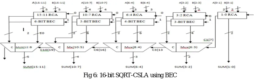
[image:5.612.100.517.529.661.2]The adder used in the FIR Filter design in this is SQRT-CSLA that is designed with RCA-BEC based. Where Cin=0 logic is given to the RCA (Ripple carry adder) and logic Cin=1 is replaced by the BEC logic as for example a 16-bit adder using BEC is shown in the below Fig 5. Whereas the bit input for the BEC in increased by one bit every time i.e; firstly 3-bit BEC is used next it gets added by 1-bit and so on.
Fig 6: 16-bit SQRT-CSLA using BEC
V. PROPOSEDSTRUCTUREOFVEDICMULTIPLIERFORFIRFILTERDESIGN
coefficient specification in certain things, which can be suitable with time domain and frequency domain. The main disadvantages of FIR filter design are more power consumption and large area size is required for multipliers, adders and delayed element in number of Nth order-based TAP. In the High performance, FIR Filter architecture will have MCM multiplication and normal adders it will perform inherently pipelined and produced the results on significant way with save computation results.
Fig 7: FIR filter design with MCM and 64-bit adder
The MCM multiplier will not identified the Signed and Unsigned operation of inputs, and not concentrate on Carry operation inside of Partial Product Addition. In the FIR filter, design will take large area and take the rigid order to meet frequency range with high performance.
VI.SYNTHESISRESULTSANDDISCUSSIONS
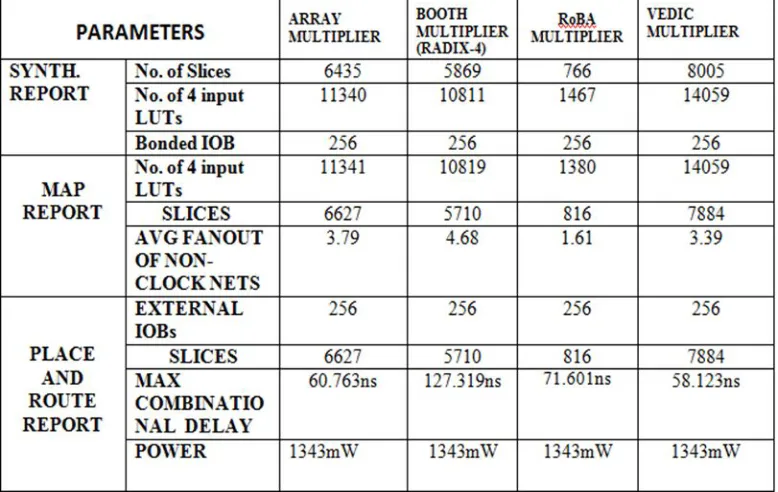
In this section, we have compared the area, delay and power of different multipliers as shown in table 2 below and also FIR filter design using different multipliers and SQRT-CSLA. These are been coded in Verilog HDL language and the simulation and synthesis results are obtained in Xilinx ISE 14.5 of family VIRTEX4 and Device XC4VLX200 of Package FF1513 of speed -11.
[image:6.612.119.508.457.703.2]Table 3: Comparison Of Fir Filter Using Different Multipliers
The Vedic multiplier occupies 75 slices and 201 LUT’s less than that of Array multiplier with delay reduction of about 3.635 ns and consumes 0.013w less than that of array multiplier. Whereas the Booth’s multiplier occupies 1945 slices and 3629 LUT’s more than that of Vedic multiplier with delay increment of about 28.258ns and consumes 0.001w more than that of Vedic multiplier. Whereas the RoBA multiplier occupies 1270 slices and 2323 LUT’s more than that of Vedic multiplier with delay increase of about 56.761ns and consumes 1.693w more than that of array multiplier.
[image:7.612.183.443.572.701.2]
Figure 8: Area of FIR Filter using different Multipliers Figure 9: Delay (ns) of FIR Filter using different Multipliers
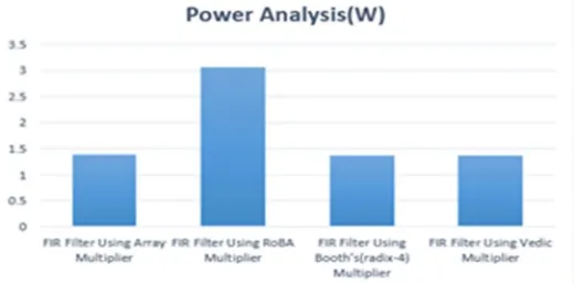
We have computed the area, power or delay for the FIR filter design using different multiplier with 64-bit input lengths. We have developed HDL code for each module for input bit length. Figures 7, 8 and 9 show the area. delay and power analysis of different multiplier architecture for 64-bit input length. The below figures show the performance analysis of FIR filter design using all the multipliers. Hence, FIR Filter using Vedic multiplier of bit size 64-bit utilizes less area, delay, and power consumption compared with Array, Booth’s and RoBA multipliers.
Hence, FIR Filter using Vedic multiplier of bit size 64-bit utilizes less area, delay, and power consumption compared with Array, Booth’s and RoBA multipliers.
VII. CONCLUSIONS
In this paper, Different multipliers is used to perform the multiplication operation for the FIR filter as this multiplier is appropriate for multiplying large number of bits in parallel. By comparing Vedic multiplier over different multipliers like Array, Booth’s and RoBA. Vedic multiplier is more suitable than all the multipliers. The synthesis results determine that the Vedic multiplier delivers low area, delay and low power is found as compared to other multipliers. The hardware complexity of Vedic procedure is less than the other multipliers. From the gained results, the FIR filter with Vedic multiplier acquires low area and low power than FIR filter using other multipliers.
In future work, the filter design can be improved for fixed applications by using parallel-prefix adder unit in Multiple Constant Multiplication (MCM) structured and its synthesis results are compared with the present works.
REFERENCES
[1] Basant Kumar Mohanty, Senior Member, IEEE, and Pramod Kumar Meher, Senior Member, "A High-Performance FIR Filter Architecture for Fixed and Reconfigurable Applications", 1063-8210 © 2015 IEEE.
[2] U Penchalaiah, Siva Kumar VG, “Performance Analysis of FIR Filter Design Using Modified Truncation Multiplier with SQRT based Carry Select Adder”, IJET, vol 7, no 2.32(2018).
[3] Deepika, Nidhi Goel, “Design of FIR filter Using Reconfigurable MAC Unit”, © 2017 IEEE.
[4] Mahvish Quraishi, V.D. Alagd- eve, “Energy efficient reconfigurable fir filter architecture” © 2017 IEEE.
[5] B. Ramkumar and Harish M Kittur, "Low-Power and Area-Efficient Carry Select Adder", IEEE TRANSACTIONS ON VERY LARGE-SCALE INTEGRATION (VLSI) SYSTEMS,1063-8210/$26.00 © 2011 IEEE.
[6] Shamim Akhter, Vikas Saini, Jasmine Saini, "Analysis of vedic multiplier using various adder topologies “, © 2017 IEEE.
[7] Amrita Nanda “Design and Implementation of Urdhva-Tiryakbhyam Based Fast 8×8 Vedic Binary Multiplier” IJERT, ISSN: 2278-0181, Vol. 3 Issue 3, March – 2014.
[8] Ankita jain, Atush jain, “Design, Implementation & Comparison of Vedic Multipliers with Conventional Multiplier”, ICECDS, © 2017 IEEE.
[9] Basant Kumar Mohanty, Senior Member, IEEE, and Sujit Kumar Patel, "Area–Delay–Power Efficient Carry-Select Adder", IEEE TRANSACTIONS ON CIRCUITS AND SYSTEMS—II: EX-PRESS BRIEFS, VOL. 61, NO. 6, JUNE 2014.
[10] O. J. Bedrij, “Carry-select adder,” IEEE IRE Transactions on Electronic Computers, Vol: EC – 11, pp. 340–344, 1962.
[11] S. Akhter, S. Chaturvedi, and K. Pardhasardi, “CMOS Implementation ofEfficient 16-Bit Square Root CSL Adder”,2nd InternationalConference on Signal Processing and Integrated Networks (SPIN), India,Noida, pp. 891 – 896, Feb 2015.
[12] Ms. Priya Meshram, Mr. Mithilesh Mahendra, Mr.Parag Jawarkar, “Designed Implementation of Modified Area Efficient Enhanced Square Root Carry Select Adder” VOLUME-2, ISSUE-5, MAY-2015.
[13] S. Akhter, “VHDL Implementation of Fast NxN Multiplier Based onVedic Mathematic”, Proc. of 18th European Conference on Circuit Theory and Design (ECCTD), pp. 472-475, Aug. 2007.
[14] U. Penchalaiah, Siva Kumar VG, “Design of high speed and energy efficient parallel prefix kogge tone adder” IEEE conference on System computation, Automation networking2018.