4288
Published By:
Blue Eyes Intelligence Engineering & Sciences Publication
Retrieval NumberJ1063088101919©BEIESP DOI: 10.35940/ijitee.J1063.0881019
Abstract: In this research, a highly efficient desensitized FIR filter is designed to enhance the performance of digital filtering operation. With regard to FIR filter design, Multiplication and Accumulation component (MAC) forms the core processing entity. Half-band filters employing Ripple Carry Adder (RCA) based MAC structures have a sizeable number of logical elements, leading to high delay and high power consumption. To minimize these issues, a modified Booth multiplier encompassing SQRT Carry Select Adder (CSLA) based MAC component is proposed for the desensitized filter with reduced coefficients and employing lesser number of logical elements forgiving optimum performance with respect to delay and power consumption. The suggested FIR filter is simulated and assessed using EDA simulation tools from Modelsim 6.3c and Xilinx ISE. The results obtained from the proposed Desensitized FIR filter employing the modified booth multiplier with reduced complexity based SQRT CSLA show encouraging signs with respect to 12.08% reduction in delay and 2.2% reduction in power consumption when compared with traditional RCA based digital FIR filter.
Keywords: MAC, SQRT CSA, RCA, Desensitized FIR filter, Half band filter.
I. INTRODUCTION
Analog filters work on analog signals which are also termed as real-time signals. They are mathematically analysed by differential equations. The main building elements of analog filters are Resistors, Capacitors and Operational Amplifiers for obtaining desired filtering responses. Analog filters are far easier to process than digital filters as there is no need for Analog to Digital conversions at low frequencies. At high frequencies, active filtering is impossible because of limitations occurring as a result of bandwidth and distortion characteristics in Op-Amp. Additionally, the filter which uses purely passive components gives less accuracy, drift due to component variations, leading to difficulty in design and simulation. Because of these disadvantages, a digital filter is preferred choice over an analog filter in many applications and domains. Digital filters process signals that are digitized or sampled.
Revised Manuscript Received on August 05, 2019
K.Manivannan, Research Scholar, Electrical Engineering Department, Annamalai University, Chidambaram, India
L.Lakshminarasimman, Associate Professor, Electrical Engineering Department, Annamalai University, Chidambaram, India
M.Janaki Rani, Professor, Electronics and Communication Engineering Department, Dr.M.G.R.Educational and Research Institute, Chennai, India
A digital filter provides a numerical representation of an input signal's convolution operation and the filter's impulse response signal. It is marked at a uniformly spaced sample interval by an expanded series of mathematical operations. By performing mathematical operations, certain key aspect of signals could be determined and enhanced. Filters can be classified into several different groups based on different criteria. Two major classifications namely: Finite Impulse Response filter (FIR) and Infinite Impulse Response filter (IIR). Both filter kinds have certain benefits and disadvantages that should be considered carefully while developing any real-time system. Another nomenclature of FIR filter is Recursive filter. The word Recursive implies "running back". In other words, for the calculation of the current output, previously calculated output values are taken into account. The IIR filter is also called a non-recursive filter, where the current and past input values are used to calculate the present output of the IIR digital filter. The half-band FIR filters are used in the field of RF / IF converters as the anti-aging up-sampling and down sampling filters. The utilization of the power is one of the major considerations for the data converter.
The following is organized this paper. Section II describes the design of different literature FIR filters. Section III explains the structure of conventional FIR filter and desensitized FIR filter in the existing system. In Section IV, the design of proposed desensitized FIR filter is presented. The results of the simulation are discussed in Section V and Section VI gives the conclusion.
II. RELATED WORKS
Fred Harris et al.[1] presented an efficient architecture for digitally converting to arbitrary center frequencies signals with arbitrary bandwidth. The architecture consisted of a 4-path, 4-to-2 up converter cascade of channelizers whose low-pass prototype filters were chosen as real half-band filters. Choosing to use half-band filters as well as selecting a four-way polyphase channelizer engine for each stage will help to keep the structure's hardware component very low. At the beginning of the up converting chain, a complex heterodyne was applied when the signal sampling rate is very low while selecting the required number of stages according to the required frequency of the signal center. Mariammal, K. et al., [2] designed the multi-rate filter for multi-rate signal processing applications.
Design of High-Speed Desensitized FIR Filter
Employing Reduced Complexity SQRT Carry
Select Adder
4289
Published By:
Blue Eyes Intelligence Engineering & Sciences Publication
Retrieval NumberJ1063088101919©BEIESP DOI: 10.35940/ijitee.J1063.0881019
Up-sampling and down sampling is a very effective process in multi-rate signal processing. The built filter provides benefits in the VLSI architecture such as less region, less delay and low power consumption. Using bypass feed direct (BFD) multiplier, the polyphase decimation filter with decimation factor (D=3) was used to achieve the above benefits. When compared to the conventional multiplier used in the filter, the designed BFD multiplier showed less power consumption. Carry look ahead adder was used in the multiplier for improving the speed and also for reduction in area. The speed of the filter was enhanced to 57.99% and area was significantly reduced to 83.3%.
Tian-Bo [3] designed an efficient two-dimensional half-band digital filter using the singular value decomposition method. The one-dimensional frequency response could be generated by zero phase SVD half band frequency. One-dimensional filter required only one multiplication to get output samples. The single multiplication reduced the computational complexity of the filter. Fred Harris et al., [4] designed the recursive filters for realizing the efficient decimation and interpolation filtering operation.
Alan and Willson [5] designed the digital half-band filter for an effective communication system. Digital half-band filter is employed for both up-sampling and down sampling in the multi-rate systems. The constructed low-pass FIR half-band filter given important insensitivity to the coefficient values of the filters to the frequency response. It offered reduced hardware components, low power consumption and high speed.
Jorgensen [6] performed the hardware optimization of half-band IIR filter. The filter design's main objective was to reduce the number of adders used in the filtering operation. Less number of adders in the filter avoided the hardware complexity; the resulting complexity could be evaluated by counting all the adders in the filters. It included both the filter coefficient and filter cells. AlirezaMehrnia et al., [7] described the optimal factoring of FIR filters by which most efficient FIR filter design could be created as a result of this research.
By exploiting the extended double base number system (EDBNS), Chen, J et al[8] presented a new design methodology for programmable FIR filters. The sharing of adders in the time-multiplexed multiple constant multiplication blocks of the programmable FIR filters can be maximized by direct mapping from the quasi-minimum EDBNS due to its dearth and innate abstraction of the sum of binary shifted partial products.
III. FIR FILTER ARCHITECTURE
This section explains how conventional FIR filters and desensitized FIR filters are structured
Finite Impulse Response (FIR) Filter
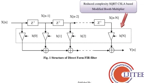
The filter Finite Impulse Response (FIR) is used to filter the noise / unwanted signals at the end of the impulse. N+1 coefficients represent a FIR filter of order N and, in general, N+1 multipliers and N two-input adders are required. Structures that are the coefficients of the transfer function in which the multiplier coefficients are called direct form structures. From the sum of the convolution, a direct form of a FIR filter can be determined immediately. The transposed FIR filter is a modification of the direct FIR model. The direct form FIR filter requires additional pipeline registers between the adders to reduce the adder tree's latency and attain high throughput. The main advantage of direct FIR filter form is that it is no longer expensive and can be operated at lower sample data rates. Multiplication and Accumulation Unit (MAC) estimates the length of periodic impulses. High performance of multiplication and accumulation architectures is therefore required to enhance digital FIR filter performance. A novel, reduced complexity modified booth multiplier based on SQRT CSLA is incorporated in this paper into the FIR direct form filter multiplication. Therefore, we can improve digital FIR filter performance compared to other best existing FIR filters.
[image:2.595.65.542.536.810.2]The generalized structure of direct form FIR filter for N-taps is illustrated in Fig.1
Fig. 1 Structure of Direct Form FIR filter
Z
-1Z
-1Z
-1X[n]
Y[n]
X[n-1]
X[n-2]
X[n-N]
h[0]
h[1]
h[2]
h[N]
4290
Published By:
Blue Eyes Intelligence Engineering & Sciences Publication
Retrieval NumberJ1063088101919©BEIESP DOI: 10.35940/ijitee.J1063.0881019
This proposed work considers 3-tap FIR filter for an 8-bit word length of input sample x[n]. Fixed coefficients are 8-bit word length, which is indicated as h[0], h[1],..h[N] in figure 1. The dotted line of fig.1 indicates the incorporation of the Modified Booth Multiplier based on reduced complexity SQRT CSLA in the digital FIR filter.
Desensitized FIR Filter Architecture
The half-band FIR filter is one of the basic blocks to
perform filter analysis in the wavelet analysis. A high-level application like digital signal processing needs half-band filter for signal filtering and processing. The half-band FIR filter transfer function is provided by equation 1.1.
(1.1)
[image:3.595.135.465.148.331.2]Where
Fig. 2 Structure of Traditional Half-band FIR filter [1] The traditional half-band FIR filter design shown in Fig.2
is based on the architecture of general FIR filters. In the FIR filter, multiplication and summation are required for achieving the higher output efficiency. Multiplication and accumulation (MAC) unit is the required process for performing the analog and digital filters. The 2 M and M-based half-band filter transfer function is equated with 1.2
(1.2)
[image:3.595.54.517.437.684.2]Where h (z) is the type II odd order transfers function. In the conventional half band FIR filter architecture, different numbers of logical elements are used for the computations, so the difficulty of the overall system is increased highly. By using desensitized filter architecture shown in Fig.3 with modified booth and SQRT CSLA adder, the overall system performance is increased. In the application of the multi-rate system, the filters are used as the versatile block.
4291
Published By:
Blue Eyes Intelligence Engineering & Sciences Publication
Retrieval NumberJ1063088101919©BEIESP DOI: 10.35940/ijitee.J1063.0881019
The requirement of the sampling rate variation is achieved by using the up and down sampling filters. The higher co-efficient sensitivity and low speed are one of the main drawbacks in the conventional filters. The desensitized filters are used to reduce the complexity of the system. By using the cascading block, the co-efficient complexity is reduced. The unit of multiplication and accumulation (MAC) plays a vital role in the digital filters of FIR. The modified booth multiplier and carry select adder is used in the desensitized FIR filters.
IV. PROPOSED DESENSITIZED FIR FILTER In this paper, using modified Booth multiplier based MAC unit, a desensitized FIR filter is designed. A reduced complexity SQRT CSLA adder is proposed in this work which is used for the implementation of modified Booth multiplier
Reduced SQRT Carry Select Adder (SQRT CSLA) Mohanty, B.K. and Patel, S.K [9] provided a design of Area-Delay-Power Efficient Carry Select Adder. Ripple
Carry Adder (RCA) is one of the basic VLSI based adders which is largely affected by carry propagation delay. Carry select adder circuit using the add-one circuit is used to replace one ripple carry adder. Carry select adder consists of a ripple carry adder with zero carry in, multiplexer and add one circuit. Carry propagation delay of the circuit is reduced by carry select adder. SQRT CSLA was developed to improve the performance of the carry select adder. In CSLA circuit [9], N-bit data is divided into groups to provide the parallelism. Hence, this circuit is named as SQRT CSLA. However, RCA based SQRT CSLA increases the delay of the circuit. So the set of RCA circuits can be replaced by Binary to Excess Code (BEC) circuit. The modified circuits have the same functionality with less number of gates and it slightly increases the speed of the adder circuit used in the MAC unit.
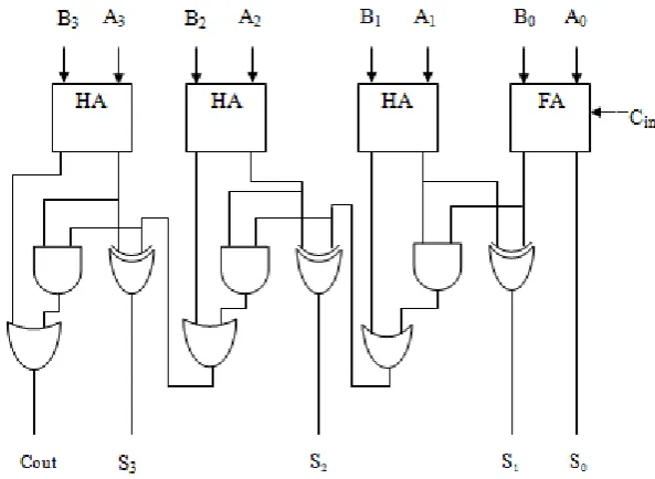
[image:4.595.155.452.313.530.2]To reduce the complexity of the hardware, the unnecessary logic function of each group structure is recognized and removed. The developed adder circuit is therefore known as "Reduced SQRT CSLA Complexity."
Fig. 4 Proposed Reduced Complexity SQRT CSLA The circuit diagram of reduced complexity SQRT CSLA
for 4-bit addition is illustrated in Fig.4. The reduced complexity SQRT CSLA reduces the logic utilization significantly. Logic utilization and gate count of the traditional group structure of SQRT CSLA is higher compared to the reduced complexity SQRT CSLA. The proposed reduced complexity SQRT CSLA adder based modified booth multiplier provide better performance than the performance of ripple carry adder based modified booth multiplier due to the less logic utilization of reduced complexity SQRT CSLA.
Modified Booth Multiplier
Booth multiplier [10] is one of the efficient designs for signed bit multiplication. Any multiplier contains three processes for computations which are partial products generation, partial products reduction, sum and carry, is added and get final results. These are the important process done in any multiplier.
The combination of modified Booth multiplier with SQRT carry select adder reduces the propagation delay. Booth multiplier generates a small number of partial products, which allows the addition to be more efficient. The number of partial products reduction can be done by grouping the bits of the multiplier into pairs, and also selecting the partial products from the set of 0, N, 2N, where N is the multiplicand. Some extra bits are added for the sign extension. Shifting and complementing is used for generation of all partial products.
4292
Published By:
Blue Eyes Intelligence Engineering & Sciences Publication
[image:5.595.138.462.57.434.2]Retrieval NumberJ1063088101919©BEIESP DOI: 10.35940/ijitee.J1063.0881019
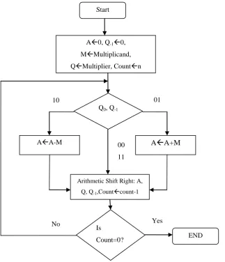
Fig. 5 Flowchart for Modified Booth Multiplier The modified booth multiplier have two modifications.
The first modification is finding the 2’s complement faster, and another one is carry select adder structure explained above. The 2’s complementation complements of all the bits after the rightmost “1” in the word but keeps the other bits as they are. The two’s complement of a binary number (001010)2 (10)10 is (110110)2(-10)10. Two's
complementation now comes down to finding the conversion signal that is utilized for specifically complementing a portion of the information bits. In the event that the change motion at any position is "0", at that point the value is kept as it is and if the conversion signal is "1", at that point the value is complemented. The conversion signal after the rightmost “1” is always 1.
They are 0 otherwise. Once a lower order bit has been detected to be a “1”, the conversion signals for the higher order bits to the left of that bit position should all be “1”.
V. RESULTS AND DISCUSSIONS
In this work, Verilog HDL is used to develop a desensitized FIR filter with modified Booth and SQRT carry select adder. The validation of the proposed filter circuit is evaluated using Modelsim 6.3C and the results of the synthesis are assessed using the design tool Xilinx ISE 10.1. Figure 6 shows the simulation result of the proposed FIR desensitized filter. In order to increase the performance of desensitized FIR filter, the high-performance MAC unit
structures are utilized. A modified Booth multiplier is designed and the developed multiplier reduces the hardware complexity than conventional multipliers. However, based on the performance of adder structure only, it can decide the best performance of multiplier. To fulfill this requirement, a reduced complexity SQRT CSLA adder is developed in this paper. This adder provides better performance regarding area and power than traditional adders like RCA, carry look ahead adder. The simulation results of proposed SQRT CSLA, Modified booth multiplier and desensitized FIR filter proposed are shown respectively in Fig.6, Fig.7 and Fig.8. Start
A0, Q-10,
MMultiplicand, QMultiplier, Countn
Q0, Q-1
AA-M
A
A+M
Arithmetic Shift Right: A,
Q, Q-1,Countcount-1
Is
Count=0? END
10 01
00 11
4293
Published By:
Blue Eyes Intelligence Engineering & Sciences Publication
[image:6.595.94.506.54.713.2]Retrieval NumberJ1063088101919©BEIESP DOI: 10.35940/ijitee.J1063.0881019
Fig. 6 Simulation result for SQRT CSLA
Fig. 7 Simulation result for Modified booth multiplier
4294
Published By:
Blue Eyes Intelligence Engineering & Sciences Publication
[image:7.595.88.510.56.147.2]Retrieval NumberJ1063088101919©BEIESP DOI: 10.35940/ijitee.J1063.0881019
Table. 1 Comparison of RCA and Reduced Complexity SQRT CSLA
Sl.No Number of Bits in Adder Delay(ns) in Adder % Reduction
RCA SQRTCSLA
1. 8 17.58 12.08 31.2
2. 16 28.4 14.72 48.75
3. 32 51.05 19.96 60.09
4. 64 95.67 28.64 70.06
The delay of 8 bit, 16 bit, 32 bit and 64 bit RCA and proposed adder are given in Table.1 and the proposed SQRT CSLA adder reduces the delay in each case and the % reduction in delay is high for a 64 bit adder circuit.
Table. 2 Comparison of Conventional and Desensitized FIR filter
Parameter Conventional FIR
Filter[2]
Desensitized FIR using
RCA %reduction
Delay(ns) 105.707ns 102.524ns 3.01%
Power (W) 1.764w 1.019w 42.2%
Table2 shows the comparison results of conventional FIR and Desensitized FIR filter and it shows that the power consumption of the desensitized FIR filter using RCA is less than that of conventional FIR filter.
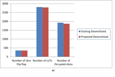
Table. 3 Comparison of Existing and Proposed Desensitized FIR filter
Parameters 16 bit-Existing
Desensitized Filter[2]
16 bit-Proposed Desensitized Filter
%reduction
Number of slice Flip-flop 354 352 0.5%
Number of LUTs 2809 2787 0.7%
Number of occupied slices 1924 1866 3.01%
Delay(ns) 102.524ns 90.134ns 12.08%
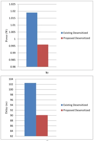
[image:7.595.118.506.481.739.2]Power (W) 1.019w 0.996w 2.2%
Table 3 shows the comparison results of the existing and proposed desensitized FIR filter. Figures 9.a, 9.b and 9.c show the performance analysis of the existing and proposed desensitized FIR filter with respect to area, power and delay respectively.
a) 0
500 1000 1500 2000 2500 3000
Number of slice Flip flop
Number of LUTs Number of Occupied slices
Existing Desensitized
4295
Published By:
Blue Eyes Intelligence Engineering & Sciences Publication
Retrieval NumberJ1063088101919©BEIESP DOI: 10.35940/ijitee.J1063.0881019
b)
[image:8.595.136.459.47.530.2]c)
Fig. 9 Desensitized FIR filter a)Area b)Power c)Delay
VI. CONCLUSION
In this paper, the design of desensitized FIR filter is done by using Verilog HDL. A modified booth Multiplier is introduced in this paper to increase the performance of MAC unit of desensitized FIR filter. Redundant logic functions of both conventional multipliers and adders are identified and removed in this work to increase the performance of MAC unit. In this work, which is used in addition to part of the modified booth multiplier, reduced complexity SQRT CSLA is developed. The 64-bit reduced complexity SQRT CSLA adder offers 3.01% reduction in occupied slices and 70.06% reduction in delay than 64-bit ripple carry adder. The proposed desensitized FIR filter using modified Booth multiplier with reduced complexity SQRT CSLA offers 12.08% reduction in delay and 2.2% reduction in power consumption than existing desensitized FIR filter.
REFERENCES
1. Harris, F., Chen, X. and Venosa, E., "An efficient cascade of half-band filters for software defined radio transmitters", IEEE Conference on Signals, Systems and Computers, pp. 990-994, 2011,ISBN:978-1-4673-0323-1.
2. Mariammal, K., Rani, S.J.V. and Kohila, T., "Area efficient high-speed low power multiplier architecture for multirate filter design", IEEE International Conference on Emerging Trends in Computing, Communication and Nanotechnology (ICECCN 2013), pp. 109-116, 2013,ISBN:978-1-4673-5036-5.
3. Deng, T.B.,"Low-complexity design of 2-D half-band filters", IEEE International Symposium on Communications and Information Technology, pp. 602-604, 2009,ISBN: 978-1-4244-4521-9.
4. Harris, F., Venosa, E., Chen, X., Kumar, P. and Dick, C.,"Comparison of standard low pass filter types in two-path half-band IIR filter structures", IEEE International Symposium on Signals, Circuits and Systems (ISSCS), pp. 1-4, 2013,ISBN:978-1-4799-3193-4.
0.98 0.985 0.99 0.995 1 1.005 1.01 1.015 1.02 1.025
P
o
w
er
(
W
)
Existing Desensitized
Proposed Desensitized
82 84 86 88 90 92 94 96 98 100 102 104
Dela
y
(
n
s)
Existing Desensitized
4296
Published By:
Blue Eyes Intelligence Engineering & Sciences Publication
Retrieval NumberJ1063088101919©BEIESP DOI: 10.35940/ijitee.J1063.0881019
5. Willson, A.N., "Desensitized half-band filters", IEEE Transactions on Circuits and Systems I, Vol. 57, No. 1, pp.152-167, 2010,ISSN: 1549-8328.
6. Jorgensen, I.H.H., Pracny, P. and Bruun, E.,"Hardware-efficient implementation of half-band IIR filter for interpolation and decimation", IEEE Transactions on Circuits and Systems II, Vol. 60, No.12, 2013,ISSN:1549-7747.
7. Mehrnia, A. and Willson, A.N.,"Optimal factoring of FIR filters", IEEE Transactions on Signal Processing, Vol. 63, No. 3, pp.647-661, 2015,ISSN:1053-587X.
8. Chen, J. Chang, C. H. Fen, F. Ding, W. and Ding, J. "Novel Design Algorithm for Low Complexity Programmable FIR Filters Based on Extended Double-Base Number System" IEEE Transaction on Circuits and Systems, Vol. 62, No.1, pp. 1-10, 2014,ISSN:1549-8328.
9. Mohanty, B.K. & Patel, S.K." Area–Delay–Power Efficient Carry Select Adder" IEEE Transactions on Circuits and Systems-II, Vol. 61, No. 6, pp.418-422, 2014,ISSN:1549-7747.
![Fig. 3 Structure of Desensitized Finite Impulse Response Filter [5]](https://thumb-us.123doks.com/thumbv2/123dok_us/8187957.256897/3.595.54.517.437.684/fig-structure-desensitized-finite-impulse-response-filter.webp)