Modeling of Single Diode Solar Photovoltaic Module
using Matlab
Md. Abu Bakr Siddique
Lecturer
Department of EEE
IUBAT - Intl. Uni. of Bus. Agri. and Tech.
Sector 10, Dhaka 1230, Bangladesh
S. M. Rezaul Karim
Lecturer
Department of EEE
IUBAT - Intl. Uni. of Bus. Agri. and Tech.
Sector 10, Dhaka 1230, Bangladesh
Shariful Islam Sharif
Graduate
Department of EEE
IUBAT - Intl. Uni. of Bus. Agri. and Tech
Sector 10, Dhaka 1230, Bangladesh
M. Tanvirul Hoque
Lecturer
Department of EEE
IIUC - International Islamic Uni. Chittagong
Kumira, Chittagong-4318, Bangladesh
ABSTRACT
This paper presents a circuit based simulation model for a solar photovoltaic (PV) module to examine the estimated electrical performance parameters with the changes of environmental parameter such as solar irradiation and temperature. Modeling and simulation of a solar PV module is presented based on Shockley diode equations. The Solarex MSX 120, a typical 120W PV module is chosen for model performance evaluation. The mathematical model for the chosen module is implemented on matlab with respect to various temperatures, solar irradiations, diode quality factors and model series resistances and obtained I-V and P-V characteristics curves were compared with the manufacturer’s published curves which show precise correspondence to the model.
Keywords
Photovoltaic module, Solar irradiation, Modeling and behavior of PV cell, Temperature, Performance parameter, Photocurrent, I-V and P-V characteristics, MSX120 PV module, Single diode.
1.
INTRODUCTION
Increasing world’s population demand more energy. The traditional nonrenewable energy source fails to fulfill the demand because is not economical and viable for sustainable development. As a result, in recent days renewable energy sources play a vital role to meet the power demand of the growing population in the world. Apart from contributing to reduce the emission of greenhouses gases, they added much expected facility to the energy sources by decreasing our dependency on fossil fuels [1]. The renewable energy source is the best solution to the power crisis problem and Solar PV is at the top of the option lists of renewable energy. As it offers some key qualities like having no waste and emission, resulting no adverse effects on the environment and ideally suited for distributed resource applications [2]. The amount of sun’s energy comes to earths is estimated as 1018
kWh/a which should be utilized [3]. Photovoltaic (PV) systems generate DC electricity when sunlight shines on the PV array. The DC power is stored to a storage system. An inverter converts DC to AC to power local loads [4].
So PV systems consist of a PV generator (cell, module, array), energy storage devices (such as batteries), DC to AC
converter (Inverter). This article refers about a model for modeling and simulation of Solarex MSX 120, a typical 120W PV module based on Shockley diode equation and Newton-Raphson iteration method in MATLAB. Single diode and two diode model provide better relations with a practical solar cell keeping in mind the simplicity in implementation and the iteration speed in the extracting parameters as well as I-V and P-V curves also give minimum error with respect to characteristics of solar PV cell as per manufacturer`s datasheet [5]. For this paper single diode model is chosen.
2.
PV MODULE BASICS
Photovoltaic (PV) effect means, when solar energy (photons) hits the solar cell, with energy greater than band gap energy of the semiconductor, electrons come out from the atoms in the material, creating electron-hole pairs. Due to the impact of the internal electric fields those carriers result current. Generated current is directly proportional to the perpetration irradiation. A PV cell, the functional unit of photovoltaic generator, is a p-n semiconductor device that converts sunlight into DC current (electricity) using photovoltaic effect. In the dark, the I-V output characteristics of a PV cell and a diode are similar. When the cell is short circuited, this current flows in the external circuit; when open circuited, this current is shunted internally by the intrinsic p-n junction diode. The characteristics of this diode therefore set the open circuit voltage characteristics of the cell [6]. Large numbers of PV cells are attached in series and parallel summation according to energy requirements. This arrangement is known as PV module. A PV array is defined as group of manifold PV modules which are altogether connected with each other in series and parallel connections to increase the array voltage and current in the array respectively [7].
3.
MODELING THE PV CELL
A PV cell is originally a silicon semiconductor junction device that contains a p-n junction similar to a diode. It generates electricity proportional to the incident sunlight. When light shines on the PV cell current flows from the p-type side to the n-p-type side across the p-n junction through wire which is known as light generated or photo current
I
Lan internal resistance to the current flow as depicted in figure 1 [8].
Figure 1: Electrical model of PV cell
The photocurrent
I
Lof the PV cell is directly proportional to the solar insolation. The output currentI
of the cell is equal to photo generated currentI
L, minus diode currentI
D, minus shunt currentI
SH.I
I
LI
DI
SH. AsR
SH
,so0
SHI
.L D
I
I
I
(1)
If
I
sis the saturation current of the diode andV
j
V
IR
s is the voltage across the diode, whereV
is the voltage across the output terminal of PV cell andR
Sis the series resistance, then the current diverted through the diode is given by: (2)Thus the equations for the I-V characteristics of the PV cell are: (3) (4) (5) (6) (7) (8) (9) (10)
Here n is known as diode quality factor which is 1 for ideal diode.
R
Sis a small resistance which represents internal losses due to current flow. The Boltzmann’s constant, A real PV cell is characterized by the following electrical parameters [9]: Short circuit current: Current that flows whenV
0
.It is due to the generation of light generated carriers. For an ideal PV cellI
SC
I
L.Therefore, it is the largest amount of current which can be drawn from the PV cell. The short circuit current increases linearly with ambient irradiation. Again, the short circuit current slightly increases with the increase in cell temperature. Open circuit voltage: Maximum voltage available from a PV cell whenI
0
.The voltage of a PV cell at night is termed asV
OC. Mathematically,
*ln
1
OC L SV
nkT q
I I
(11)Here
nkT q
is the thermal voltage andT
is the absolute temperature of the PV cell. The open circuit voltage increases logarithmically with the ambient irradiations. Again, the open circuit voltage decreases linearly with the increase in cell temperature and thus cell becomes less efficient. Maximum power point: Operating points that provide maximum output power. Mathematically, max max*
max OC*
SC*
P
V
I
V
I
FF
(12)Here
FF
is the fill factor. Efficiency: Determined as the fraction of incident power which is converted to electricity. max incident max*I
max incP
P
V
P
(13)Fill factor: It is the ratio of the maximum power from the PV cell to the product of
V
OCandI
SC. Expressed as: max OC*
SC max*I
max OC*
SCFF
P
V
I
V
V
I
(14)Fill factor is determined from measurement of the I-V curve and for good PV cells its value is greater than 0.7.
In this experiment, Solarex MSX120, a 120W PV module is used to examine the electrical performance parameters for different environmental parameters. This module consists of 72 multi-crystalline silicon solar cells configured as four series strings of 18 cells each. When light incidents on it, it produces photocurrent,
I
Ldirectly proportional to the solar irradiation. A Matlab program is developed for implementing the model of this PV module. This program calculates thecurrent
I
using typical electrical parameters of the moduleand the variable voltage
V
, irradiation
G
andtemperature
T
.
exp
S1
D S
q V
IR
I
I
nkT
exp
S1
L S
q V
IR
I
I
I
nkT
1
1
1
L L o
I
I T
K T
T
1*
1,
L T T nom nom
I
G Isc
G
2 1
2 1
o SC T SC T
K
I
I
T
T
3 * 1
1 1
1
*
1*
n qVg nk T T
S S T
I
I
T T
e
1 1
1 1 qVoc T nkT
1
S T SC T
I
I
e
1
S Voc V
R
dV dI
X
1 11
*
1*
qVoc T nkTV S T
Typical electrical characteristics of MSX120, 120W PV module is shown in table 1. These data represent the performance of a typical MSX120, wired in 24V configuration, as measured at its output terminals, and do not include the effect of additional equipment such as diode and cabling. Note that all the data are based on measurements made in a solar simulator at standard test conditions (STC) such as Illumination of 1 kW/m2 (1 sun) at spectral distribution of AM 1.5 and Cell temperature of 25°C or as otherwise specified on the curves. Electrical characteristics of MSX-120s wired in 12V configuration could be found on the 12V I-V curve scales, or by doubling 24V current data and halving 24V voltage data.
Under most operating conditions, the cells in a module operate hotter than the ambient temperature. NOCT (Nominal Operating Cell Temperature) is an indication of this temperature rise, and is the cell temperature under Standard Operating Conditions (SOC), such as i) 20°C ambient temperature, ii) solar irradiation of 0.8 kW/m2, and iii) average wind speed of 1 m/s with the wind oriented parallel to the plane of the array, and all sides of the array fully exposed to the wind.
Table 1: Typical electrical characteristics of Solarex MSX120, 120W PV module[10]
Parameter Value
Maximum power
2max
P
120W
Voltage at
P
max,max
V
34.2V
Current at
P
max,I
max 3.5AMinimum
P
max 114WShort-circuit current
I
SC 3.8AOpen-circuit voltage
OC
V
42.6V
Temperature coefficient
of
I
SC
0.0650.015 %
ºCTemperature coefficient of
V
OC
160 20
mV ºC
Temperature coefficient
of power
º
0.5 0.05 % C
Maximum system voltage
600V
Maximum series fuse rating
20A
The series resistance is considered in the model which makes the solution for current I, a nonlinear problem, that could be solved by numerical methods. Newton-Raphson method is used as it offers rapid convergence for both positive and negative currents. A matlab script file is implemented considering the parameters of the chosen PV module.
4.
IMPACT OF ENVIRONMENTAL
VARIABLES ON PROPOSED MODEL
There are some model equations to determine the impact of the ambient irradiation G and the cell temperature T on the cell characteristics. Photocurrent IL (A) is directly proportional
to solar irradiance G (W/m2). The diode allows negligible current to flow in short circuit mode. Hence the proportionally constant in (eqn. 5) has to set in such a way so that the rated short circuit current ISC could be delivered under rated
irradiation. Generally solar intensities are considered with respect to full solar radiation at sea level with average humidity and aerosol particulate concentration (1 Sun = 1000Watt/m2). But, there is no significant variation of the PV cell performance between full sun and cloudy conditions. Output power is directly proportional to the incident solar energy where the efficiency remains constant. Change of photo-current with the change of temperature (eqn. 6) express that the relationship between the photo-current and temperature is linear (eqn. 4). Shockley equation gives the relationship between the cell’s terminal voltage and current for a not illuminated cell. Open circuited and illuminated cell has photo-current through it. Here, I-V curve is offset from the origin by the photo generated current IL (eqn. 1). The open
circuit voltage and short circuit current at 25°C are used to calculate (eqn. 8) the saturation current IS at that temperature.
For “ideality factor”, according to Green’s statements, it takes a value between 1 and 2, being close to one at high currents, ascending towards two at low currents and 1.3 ideality factor is suggested as typical in normal operation and initial use [11-13]. The relationship of IS to temperature is complex, but
contains no variables requiring evaluation (eqn. 7) [14]. Where the series resistance of the circuit has a great influence on the slope of the I-V curve at V = VOC. Equations 9 and 10
are found by differentiating equation 1, evaluating at V = VOC
and rearranging in terms of Rs [15].
5.
SIMULATION RESULTS OF THE
MATLAB PV MODEL
The result of the MATLAB function is shown for various irradiation levels, temperatures, diode quality factors, and model series resistances. The plots of I-V and P-V curves are produced by varying certain parameter at one time and keeping other parameters constant at standard test conditions. The mathematical program for MSX120, 120W PV module is implemented in matlab script file as shown in figure 2.
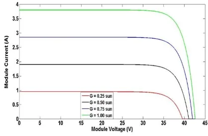
Figure 3 and figure 4 shows I-V and P-V characteristics curves for various solar irradiations (0.25, 0.5, 0.75, 1 suns) respectively. From figure 3, it is observed that cell current increases proportionally with the increase of irradiation, but cell voltage increases very little. From figure 4, output power also increases with the increase of irradiation and reaches nominal power point at standard test conditions.
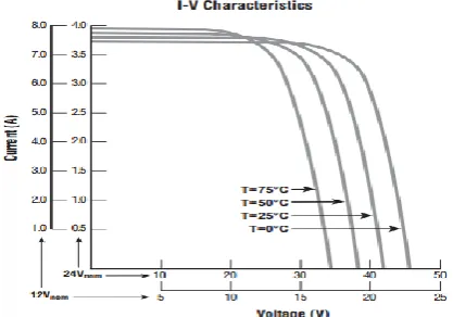
Figure 5 shows I-V characteristics curves for various temperatures (0℃, 25℃, 50℃, 75℃). From figure 5, it is seen that with the increase in temperature cell current increases slightly but cell voltages decreases significantly. Figure 6, the I-V characteristics curves of Solarex MSX120 PV module 472C
[image:3.595.54.282.345.746.2]which is directly taken from the manufacturer’s published curves, shows excellent correspondence to the matlab PV model simulated I-V characteristics curve shown in figure 5. Figure 7 shows P-V characteristics curves for various temperatures (0℃, 25℃, 50℃, 75℃). From this figure, output power decreases with the increase in temperature.
FunctionIa = msx120i(Va,Suns,TaC)
% msx120.m model for the MSX-120 solar array
% current given voltage, illumination and temperature
% Ia = msx120(Va,G,T) = array voltage
% Ia,Va = array current,voltage
% G = num of Suns (1 Sun = 1000 W/mˆ2)
% T = Temp in Deg C
k = 1.38e-23; % Boltzman’sconst
q = 1.60e-19; % charge on an electron
% enter the following constants here, and the model will be % calculated based on these for 1000W/mˆ2
n = 1.25; % "diode quality" factor, =2 for crystaline, <2 for amorphous
Vg = 1.12; % band gap voltage, 1.12eV for xtal Si, ˜1.75 for
amorphous Si.
Ns = 72; % number of series connected cells (diodes)
T1 = 273 + 25;
Voc_T1 = 42.6 /Ns; % open cct voltage per cell at temperature T1
Isc_T1 = 3.8; % short cct current per cell at temp T1
T2 = 273 + 75;
Voc_T2 = 34.6 /Ns; % open cct voltage per cell at temperature T2
Isc_T2 = 3.92; % short cct current per cell at temp T2
TaK = 273 + TaC; % array working temp
TrK = 273 + 25; % reference temp
% when Va = 0, light generated current IL_T1 = array short cct current
% constant "a" can be determined from Iscvs T
IL_T1 = Isc_T1 * Suns;
a = (Isc_T2 - Isc_T1)/Isc_T1 * 1/(T2 - T1);
IL = IL_T1 * (1 + a*(TaK - T1));
Vt_T1 = k * T1 / q; % = n * kT/q
Is_T1 = Isc_T1 / (exp(Voc_T1/(n*Vt_T1))-1);
Is_T2 = Isc_T2 / (exp(Voc_T2/(n*Vt_T1))-1);
b = Vg * q/(n*k);
Is = Is_T1 * (TaK/T1)^(3/n) .* exp(-b.*(1./TaK - 1/T1));
X2v = Is_T1/(n*Vt_T1) * exp(Voc_T1/(n*Vt_T1));
dVdI_Voc = - 1.15/Ns / 2; % dV/dI at Voc per cell --% from manufacturers graph
Rs = - dVdI_Voc - 1/X2v; % series resistance per cell
% Ia = 0:0.01:IL;
Vt_Ta = n * 1.38e-23 * TaK / 1.60e-19;%=A*kT/q
% Ia1 = IL - Is.*( exp((Vc+Ia.*Rs)./Vt_Ta) -1);
% solve for Ia: f(Ia) = IL - Ia - Is.*( exp((Vc+Ia.*Rs)./Vt_Ta) -1) = 0;
% Newton’s method: Ia2 = Ia1 - f(Ia1)/f’(Ia1)
Vc = Va/Ns;
Ia = zeros(size(Vc));
% Iav = Ia;
for j=1:9; Ia = Ia- ...
(IL - Ia - Is.*( exp((Vc+Ia.*Rs)./Vt_Ta) -1))...
./ (-1 - (Is.*( exp((Vc+Ia.*Rs)./Vt_Ta) -1)).*Rs./Vt_Ta);
% Iav = [Iav;Ia]; % to observe convergence for debugging.
end
[image:4.595.329.538.587.724.2]Figure 2: Matlab script file for the MSX120 PV module
Figure 3: Matlab model I-V curves for various irradiation levels (MSX120, G = 0.25, 0.5, 0.75, and 1.00 Sun, T =
Figure 4: Matlab model P-V curves for various irradiation levels (MSX120, G = 0.25, 0.5, 0.75, and 1.00 Sun, T = 25℃)
[image:5.595.62.273.80.240.2]Figure 5: Matlab model I-V curves for various temperatures (MSX120, G = 1.00 Sun, T = 0℃, 25℃, 50℃, 75℃)
Figure 6: I-V characteristics curves of Solarex MSX120, 120W PV module directly taken from manufacturer’s
published datasheet
Figure 7: Matlab model P-V curves for various temperatures (MSX120, G = 1.00 Sun, T = 0℃, 25℃, 50℃, 75℃)
Figure 8: Matlab model I-V curves for various diode quality factors (MSX120, G = 1.00 Sun, T = 25℃, n = 1,
1.25, 1.50, 1.75 and 2)
Figure 8 shows I-V characteristics curves for various diode quality factors (n = 1, 1.25, 1.5, 1.75, 2). From figure 8, it is observed that the knee of the curve becomes softer with the increase of diode quality factor.
[image:5.595.62.283.291.449.2] [image:5.595.316.542.304.484.2] [image:5.595.66.275.504.650.2]Figure 9: Matlab model I-V curves for various model series resistances (MSX120, G = 1.00 Sun, T = 25℃, Rs= 0Ω, 8mΩ, 16mΩ, 24mΩ, 32mΩ)
6.
CONCLUSION
In this paper, a single diode generalized PV system with MSX120, 120W PV module is presented. The proposed system has been simulated in Matlab. Then the PV array is analyzed under the changes of solar irradiation, temperature, diode quality factor, and model series resistances. The simulation results show that PV output power, voltage, and current vary with the changes of solar irradiation, temperature, diode quality factor, and model series resistances. The current-voltage (I-V) and power-voltage (P-V) characteristic curves from the Matlab model show excellent correspondence to the manufacturer’s published curves. This paper is the first step to analyze the single diode Photovoltaic model’s characteristic curves for various environmental and electrical parameters. Our next endeavor is to analyze the double diode model.
7.
REFERENCES
[1] Lopes, L. and A.-M. Lienhardt. A simplified nonlinear power source for simulating PV panels. in Power Electronics Specialist Conference, 2003. PESC'03. 2003 IEEE 34th Annual. 2003: IEEE.
[2] Agarwal, V. and A. Vishwakarma. A comparative study of PWM schemes for grid connected PV cell. in Power Electronics and Drive Systems, 2007. PEDS'07. 7th International Conference on. 2007: IEEE.
[3] Siddique, A.B., et al. Study of PV implementation for electricity generation in Bangladesh. in Green Energy and Technology (ICGET), 2015 3rd International Conference on. 2015: IEEE.
[4] Kroposki, B. and R. DeBlasio. Technologies for the new millennium: photovoltaics as a distributed resource. in Power Engineering Society Summer Meeting, 2000. IEEE. 2000: IEEE.
[5] Tamrakar, V., S. Gupta, and Y. Sawle, Single-Diode and Two-Diode Pv Cell Modeling Using Matlab For Studying Characteristics Of Solar Cell Under Varying Conditions. Electrical & Computer Engineering: An International Journal, 2015. 4(2): p. 67-77.
[6] González-Longatt, F.M., Model of photovoltaic module in Matlab. Ii Cibelec, 2005. 2005: p. 1-5.
[7] Javed, S.B., et al. Implementation of Generalized Photovoltaic System with Maximum Power Point
Tracking. in Proceedings of 2nd International Multi-Disciplinary Conference. 2016.
[8] Femia, N., et al., Optimization of perturb and observe maximum power point tracking method. IEEE transactions on power electronics, 2005. 20(4): p. 963-973.
[9] Sagor, R.H. and M. Abido. Study of solar energy for PV implementation in Saudi Arabia. in Energy Conference and Exhibition (EnergyCon), 2010 IEEE International. 2010: IEEE.
[10]Solarex MSX120, 120W PV module datasheet. http://www.solartaos.com/PDF/PV_Panels/solarexmsx12 0.pdf
[11]Healy, S. and M. Green, Efficiency enhancements in crystalline silicon solar cells by alloying with germanium. Solar energy materials and solar cells, 1992. 28(3): p. 273-284.
[12]Wenham, S. and M. Green, Silicon solar cells. Progress in Photovoltaics: Research and Applications, 1996. 4(1): p. 3-33.
[13]Zhao, J., et al., Twenty‐four percent efficient silicon solar cells with double layer antireflection coatings and reduced resistance loss. Applied Physics Letters, 1995. 66(26): p. 3636-3638.
[14]Walker, G.R., Evaluating MPPT converter topologies using a MATLAB PV model. AUPEC 2000: Innovation for Secure Power, 2000. 1: p. 138-143.
[15]Gow, J. and C. Manning, Development of a photovoltaic array model for use in power-electronics simulation studies. IEE Proceedings-Electric Power Applications, 1999. 146(2): p. 193-200.
8.
AUTHOR’ PROFILE
Md. Abu BakrSiddique received his B.Sc. in Electrical and Electronic Engineering (EEE) from Islamic University of Technology (IUT), OIC, Bangladesh in November 12, 2014.
His main areas of research interest are Photovoltaic (PV), Solar Cell, Renewable energy, Green energy, Power system stability and control, electrical machine, energy storage system (ESS), biomedical engineering, nanotechnology and Control system.
At present, Md. Siddique is working as a full time Lecturer at IUBAT – International University of Business Agriculture and Technology in EEE Department since January 13, 2015. He has teaching experiences on Power System Analysis (EEN 453), Power System Analysis Lab (EEN 454), Microprocessor Systems and Interfacing (EEN 373), Microprocessor Systems and Interfacing Lab (EEN 374), Feedback System Analysis and Design (EEN 407), Feedback System Analysis and Design Lab (EEN 408) at IUBAT.
S. M. Rezaul Karim is working as a Lecturer of Electrical and Electronics Engineering (EEE) Department of IUBAT - International University of Business Agriculture and Technology, Dhaka, Bangladesh. Before joining in IUBAT, Mr. Karim completed his M.Sc. in IT from Institute of Information Technology, University of Dhaka (DU).
interest are smart grid, fiber optics transmission, renewable energy etc.
M. Tanvirul Hoque is currently working as a Lecturer at International Islamic University Chittagong (IIUC), in the department of Electrical and Electronic Engineering (EEE). He received his B.Sc. in Electrical and Electronic Engineering (EEE) from Islamic University of Technology (IUT), OIC,
Bangladesh in November 12, 2014.

![Table 1: Typical electrical characteristics of Solarex MSX120, 120W PV module [10]](https://thumb-us.123doks.com/thumbv2/123dok_us/9299847.428510/3.595.54.282.345.746/table-typical-electrical-characteristics-solarex-msx-pv-module.webp)