ISSN Online: 2327-5901 ISSN Print: 2327-588X
DOI: 10.4236/jpee.2018.63003 Mar. 29, 2018 28 Journal of Power and Energy Engineering
An Investigation on Performance of a
Horizontal Entrained Flow Gasifier
Isack A. Legonda
Department of Mechanical and Industrial Engineering, University of Dar es Salaam, Dar es Salaam, Tanzania
Abstract
A novel study on biomass-air gasification using a horizontal entrained-flow gasifier has been conducted. The use of a horizontal entrained-flow gasifier reactor was employed to assess the effect of the gasifier reactor orientation on the gasification process. The gasification experiments were conducted at 800˚C and equivalence ratio of 0.23 while maintaining gas hourly space veloc-ity (GHSV) of 8000 h−1. Preparation and characterisation of wood powder were performed using classical methods. The research findings showed that maximum fuel conversion and cold gas efficiency using a horizontal en-trained-flow gasifier were 99% and 70% respectively compared to 91% and 62% respectively of the vertical design. Moreover, the gasifier length can also be reduced from the common 1000 - 2000 mm to 500 mm. In general, the re-sults of this study suggest that there exists a sensitivity to the gasifier orienta-tion on the overall gasificaorienta-tion process.
Keywords
Gasification, Entrained-Flow, Syngas
1. Introduction
Biomass gasification has been achieved through different reactor designs in-cluding entrained-flow types. Entrained-flow gasifiers (EFG) have been used successfully for coal gasification since 1950. The majority of these gasifiers are of a slagging type and operate at higher pressures. Typical operating pressure ranges from 20 - 70 bar and temperatures are above 1400˚C. Although the ele-vated conditions ensure high fuel conversion and destruction of tar, the condi-tions are achieved at the expense of high oxygen consumption, as well as needing an efficient heat recovery system. On the other hand, gasification at atmospheric
How to cite this paper: Legonda, I.A. (2018) An Investigation on Performance of a Horizontal Entrained Flow Gasifier. Journal of Power and Energy Engineering, 6, 28-37.
https://doi.org/10.4236/jpee.2018.63003
Received: March 12, 2018 Accepted: March 26, 2018 Published: March 29, 2018
Copyright © 2018 by author and Scientific Research Publishing Inc. This work is licensed under the Creative Commons Attribution International License (CC BY 4.0).
DOI: 10.4236/jpee.2018.63003 29 Journal of Power and Energy Engineering pressure is also possible. For atmospheric gasification conditions, the feed me-chanisms are of the premix type and operate at high velocity to avoid flash back. High velocities lead to increased syngas yield.
There are various criteria for classifying entrained flow gasifiers including the flow configuration. The common designs are down-flow and up-flow reactors. In both designs, the fuel feedstock and oxidizing agents (usually oxygen and steam) are introduced into a reactor in co-current flow. The down-flow confi-guration is intended to improve slag separation and makes gravity fuel feed possible [3] [5]. However, owing to the short space residence time of the fuel particles, the length of the gasifier is crucial in attaining efficient fuel conversion. While a shorter reactor may result in poor fuel conversion, a longer reactor is associated with increased energy production cost.
On the other hand, the up-flow reactor is mainly characterized by large recir-culation resulting from temperature differences, thus increasing particle resi-dence time. This increase results in improved fuel burn-out and syngas quality. However, with excessive recirculation zones, caution must be applied, as the re-verse flow may cause flash back.
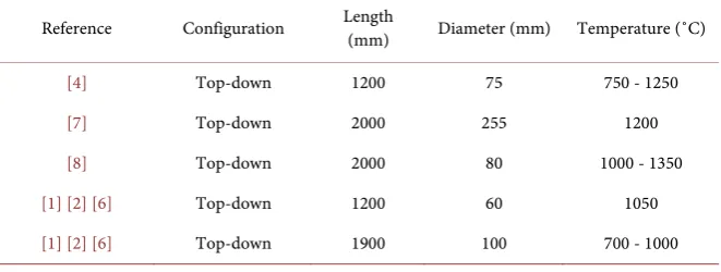
Recent developments in the field of entrained-flow gasification have led to an interest in using biomass as the fuel feedstock. This arises from its higher reac-tivity compared to that of coal. A number of research studies have been carried out on entrained flow air gasification at non-slagging temperatures (~700˚C - 1100˚C) [1][2][6]. In most cases, the gasifier reactor has been configured verti-cally employing a down flow regime as highlighted in Table 1. Although this configuration improves particulate separation from the product gas, more heat and manufacturing materials are required due to long gasifier reactors (1200 - 2000 mm). Moreover, the heating value of the product gas has been reported to be below 6.0 MJ/N·m3.
[image:2.595.208.539.602.727.2]Thus, this study focused on the effect of gasifier reactor orientation on gasifi-cation process. The gasifier sized 3 kW was configured horizontally to increase the particles residence time as opposed to a vertical entrained-flow system, where gravity forces result in lower residence time. Additionally, the enhanced particle to metal surface contact promotes heat transfer to the particle, thus in-creasing fuel conversion.
Table 1. Typical geometrical parameters of the entrained-flow gasifier reactors.
Reference Configuration Length (mm) Diameter (mm) Temperature (˚C)
[4] Top-down 1200 75 750 - 1250
[7] Top-down 2000 255 1200
[8] Top-down 2000 80 1000 - 1350
[1][2][6] Top-down 1200 60 1050
DOI: 10.4236/jpee.2018.63003 30 Journal of Power and Energy Engineering
2. Methodology
2.1. Characterisation of Sawdust
Commercial pine sawdust was reduced to pass a test sieve with an aperture of 250 μm using a grinding mill and further prepared for characterisation accord-ing to BS EN 15413:2011 standard [9]. The proximate analysis was determined using standard [10][11][12][13]. Proximate analysis expresses the properties of a particular fuel with regard to moisture, ash, fixed carbon, and volatile matter. These properties are important in assessing the characteristics of a particular fuel during combustion.
Ultimate analysis involves determination of the elemental composition of a fuel. Most commonly, carbon, hydrogen, nitrogen, sulphur and oxygen (CHNSO) are measured in a particular fuel through complete combustion. These elements are important in determining an appropriate air-fuel ratio for the combustion or gasification process. In this study, the ultimate analysis of pine sawdust was analyzed in a CHNSO-IR spectrometry (LECO) according to the BS 1016:1996 standard [14].
[image:3.595.127.539.427.702.2]2.2. The Experimental Rig
Figure 1 shows the schematic layout and the experimental test rig used in this
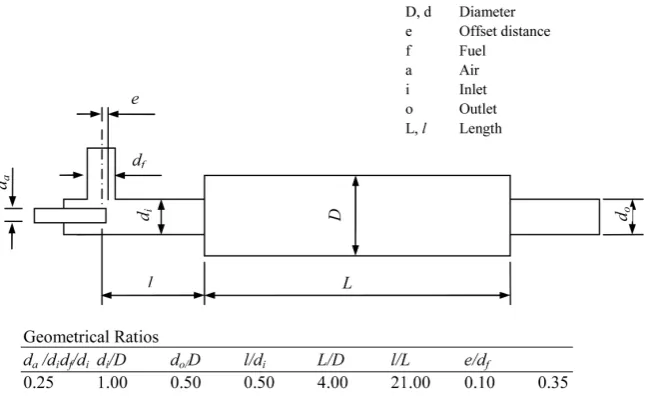
study. The rig consisted of a gasification reactor fitted in a tube furnace, fuel feeder (with injector), tar trap system, vacuum pump and gas chromatograph (GC). Detailed geometrical ratio of the gasifier is illustrated in Figure 2. Other
DOI: 10.4236/jpee.2018.63003 31 Journal of Power and Energy Engineering
Figure 2. Geometric parameters of the gasifier reactor.
components included standard fittings to provide connections. Air rotameters (from Fisher Controls Ltd.) were used for measuring the air inflow rate and the syngas outflow. Their operating limit ranged between 0 and 24 l/min at ±5% ac-curacy of full scale. The air rotameter for syngas measurement was adjusted based on the density difference to take account of the syngas composition. The density of syngas (ρgas) was determined using Equation (1) and the volume flow rate (Vgas) was determined using Equation (2). The general set-up allowed sam-pling the whole gas stream to avoid bias caused by flow dynamics.
1
n
gas i i
ρ =
∑
=ρ (1)air
gas air
gas
V ρ V
ρ =
(2)
where i is the gas component in the syngas as determined by GC in the prelimi-nary tests while ρair and Vair are density and volume flow rate of air respec-tively.
2.3. Experimental Data Measurements
2.3.1. TemperaturesThe gasification process is highly dependent on operating temperatures as it af-fects the product gas composition. Similarly, the isopropanol solvent solution requires low temperatures to prevent vaporization which reduces the perfor-mance of the tar sampling system [15]. Measuring these temperatures was im-portant in controlling the overall process.
DOI: 10.4236/jpee.2018.63003 32 Journal of Power and Energy Engineering 100˚C - 1300˚C. Prior to gasification trials, the temperature distribution along the gasifier was measured to ensure uniform heating and establish a reference position for the thermocouple. The furnace was heated to 800˚C where the tem-peratures were taken at an interval of 50 mm using a K-type thermocouple, while purging air at a flow rate of 5 l/min. During the gasification trials, the time interval for data acquisition was set at 30 seconds.
2.3.2. Syngas Analysis
In this study, the syngas composition was analyzed using a micro gas chromato-graph (Varian, CP-4900). The GC was controlled with a Galaxie Workstation using software version 1.9.3.2. Prior to measurements, the GC was calibrated on air and a standard syngas mixture (sourced from Scientific & Technical Gases Ltd.). The standard was composed of 15% H2, 15% CO, 15% CO2, 5% CH4, 2% C2H6, 2% C3H8, 1% n-Butane and the balance was nitrogen in volume percen-tage. This gas composition is typically found in gasification processes where air is employed as an oxidizing agent. On average, the accuracy of the GC for the calibration gas was found to be ±1% error.
2.4. Fuel Conversion and Cold Gas Efficiency
Fuel conversion and cold gas efficiency (CGE) are major parameters for assess-ing the performance of the gasification process. The former expresses the fuel proportion converted into gas products. While the latter, is defined as the ratio of energy content in the syngas to the biomass energy content. Fuel conversion was calculated using Equation (3) and the CGE was calculated using Equation (4) [2]. The fractions of char in the gasification residues were determined using a Leco SC-144DR, Total Carbon Analyzer.
[ ]
% 1 c 100f
f m X
m
= − ×
(3)
[ ]
% g g 100CGE
f f
m LHV
m LHV
η
= × × ×
(4)
where mc, mg and mf are the mass of unburnt carbon, syngas and fuel re-spectively. LHVg is the lower heating value of syngas and LHVf for the par-ent solid fuel.
3. Results and Discussions
3.1. Material Characterisation
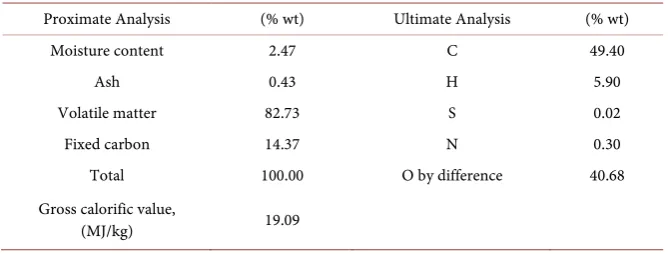
Table 2 highlights the proximate and ultimate analysis of a commercial wood
DOI: 10.4236/jpee.2018.63003 33 Journal of Power and Energy Engineering
Table 2. Proximate and ultimate analysis of sawdust.
Proximate Analysis (% wt) Ultimate Analysis (% wt)
Moisture content 2.47 C 49.40
Ash 0.43 H 5.90
Volatile matter 82.73 S 0.02
Fixed carbon 14.37 N 0.30
Total 100.00 O by difference 40.68
Gross calorific value,
(MJ/kg) 19.09
pneumatic feed which is crucial in entrained flow gasification. The ultimate analysis show that carbon and hydrogen values are 49.40% and 5.90% respec-tively. The oxygen content is high at 40.68 which must be taken into account during the gasification process. Sulphur is found in trace amount (0.02%) which consumes oxygen during combustion, thus, need to be considered in determin-ing air-fuel ratio for gasification process.
3.2. Gasification Conditions
This section highlights the nominal conditions for the gasification process used during the experimental study. The temperature in the gasifier reactor was taken at the center which was 250 mm from the gasifier inlet. The measured tempera-ture for the gasifier and tar trap system during biomass gasification test are shown in Figure 3(a) and Figure 3(b) respectively.
It can be seen from Figure 3(a) that temperature in the gasifier peaked at the start of the gasification test and stabilizes thereafter. The peak reached 872˚C and thereafter remains in the range of 853˚C to 798˚C. From Figure 3(b) it can be seen that the temperature in the tar sampling system increased with time from −10˚C to 16˚C.
The observed peak in the gasifier highlights the existence of the combustion process favoured by high air-fuel ratio for the gasification process. For the tar sampling system, the rise in temperature can be linked to the heat exchange be-tween syngas and isopropanol solution. It should be noted that tar compounds such as benzene and toluene can slip in the tar sampling system at ambient tem-peratures due to their low volatility [16]. Therefore, a combination of sampling time and temperature of the isopropanol can affect the concentration of tar compounds. The loss of isopropanol due to temperature rise has also been re-ported by Malhotra [17].
3.3. Performance of the Horizontal Entrained-Flow Gasifier
3.3.1. Fuel ConversionDOI: 10.4236/jpee.2018.63003 34 Journal of Power and Energy Engineering
Figure 3. Temperature pattern of the experimental set-up. (a) Tem-perature profile in the gasifier; (b) TemTem-perature profile in the tar sam-pling system.
87.4% by Zhao et al. [1] who used a vertical configuration. A possible attribute to this higher conversion could be due to the particle to metal contact. It should be noted that the gasifier wall acts as a heat source to initiate and sustain the gasifi-cation process in addition to the heat of combustion from the feedstock. Stain-less steel is believed to have good heat transfer properties, thus, improving fuel conversion. Another attributing factor could be the geometrical ratios of the ga-sifier reactor which enhances low temperature gradient across the reactor.
3.3.2. Cold Gas Efficiency (CGE)
DOI: 10.4236/jpee.2018.63003 35 Journal of Power and Energy Engineering
Table 3. Syngas composition and yields from biomass gasification using a horizontal en-trained-flow gasifier reactor.
Parameter Gas Composition (vol. %, db) Gas yield (N·m3/kg fuel, db)
H2 14.33 0.29
CO 22.11 0.45
CO2 13.97 0.29
CH4 3.62 0.07
C2H6 1.66 0.03
C3H8 0.38 0.01
N2 43.93 0.90
Char (g) 0.18
Gas ratios
CO/CO2 1.58
H2/CO2 1.03
CH4/CO2 0.12
H2/CO 0.65
LHV (MJ/N·m3) 6.67
Fuel Conversion (%) 99.0
Cold gas efficiency (%) 70.0
energy mainly in the form of tar and fractions of char. Comparing with the pre-vious studies for the vertical entrained flow gasifier undertaken at similar condi-tions, the highest CGE achieved was in the range of 40.77% to 62.8% [1][6][18]. The observed increase on CGE substantiates the conversion efficiency of the ho-rizontal entrained-flow gasification of biomass feedstock.
3.3.3. Syngas Composition
Table 3 shows the syngas composition from gasification of biomass using a
ho-rizontal entrained-flow gasifier reactor. It can be seen from the table that the maximum H2 achieved was 14.33%, while CO, CO2 and CH4 were 13.97%, 22.11% and 3.62% by volume respectively. Moreover, light hydrocarbons such as ethane (C2H6) and propane (C3H8) were detected in trace amounts. With this gas composition, the corresponding low heating value was found to be 6.67 MJ/Nm3 compared to a maximum of 6.0 MJ/N·m3 reported on vertical configuration. Furthermore, the CO/CO2 and H2/CO2 ratios were more than 1 and the yield of total energy containing gases (H2, CO, CH4, C2H6 and C3H8) was 0.85 N·m3/kg of fuel.
DOI: 10.4236/jpee.2018.63003 36 Journal of Power and Energy Engineering
4. Conclusion and Recommendation
It has been shown that there exists a sensitivity to the gasifier orientation on the overall gasification process. The horizontal configuration showed high fuel con-version compared to the vertical design. The maximum fuel concon-version was 99% while syngas heating value and cold gas efficiency were 6.67 MJ/N·m3 and 70% respectively, while the vertical design has 80% - 91% fuel conversion with CGE ranging 40% - 63%. Furthermore, using a horizontal configuration, the gasifier reactor length can be reduced from 1000 - 2000 mm to 500 mm with an inlet to the reactor diameter ratio of 0.5. The experimental work covered in this study was mostly conducted at a fixed gasifier reactor temperature and equivalence ra-tio to provide a strong basis for further investigara-tions. Possible future studies may include experimentation at different operating conditions such as tempera-ture, equivalence ratio and gasifying agent to explore their effect on the syngas.
References
[1] Zhao, Y.J., Sun, S.Z., Zhou, H., Sun, R., Tian, H.M., Luan, J.Y. and Qian, J.A. (2010) Experimental Study on Sawdust Air Gasification in an Entrained-Flow Reactor. Fuel Processing Technology, 91, 910-914.https://doi.org/10.1016/j.fuproc.2010.01.012 [2] Hernandez, J.J., Aranda-Almansa, G. and Bula, A. (2010) Gasification of Biomass
Wastes in an Entrained Flow Gasifier: Effect of the Particle Size and the Residence Time. Fuel Processing Technology, 91, 681-692.
https://doi.org/10.1016/j.fuproc.2010.01.018
[3] Zhou, J.S., Chen, Q., Zhao, H., Cao, X.W., Mei, Q.F., Luo, Z.Y. and Cen, K.F. (2009) Biomass-Oxygen Gasification in a High-Temperature Entrained-Flow Gasifier.
Biotechnology Advances, 27, 606-611.
https://doi.org/10.1016/j.biotechadv.2009.04.011
[4] Lapuerta, M., Hernandez, J.J., Pazo, A. and Lopez, J. (2008) Gasification and Co-Gasification of Biomass Wastes: Effect of the Biomass Origin and the Gasifier Operating Conditions. Fuel Processing Technology, 89, 828-837.
https://doi.org/10.1016/j.fuproc.2008.02.001
[5] Kajitani, S., Suzuki, N., Ashizawa, M. and Hara, S. (2006) CO2 Gasification Rate
Analysis of Coal Char in Entrained Flow Coal Gasifier. Fuel, 85, 163-169. https://doi.org/10.1016/j.fuel.2005.07.024
[6] Zhao, Y.J., Sun, S.Z., Tian, H.M., Qian, J., Su, F.M. and Ling, F. (2009) Characteris-tics of Rice Husk Gasification in an Entrained Flow Reactor. Bioresource Technol-ogy, 100, 6040-6044.https://doi.org/10.1016/j.biortech.2009.06.030
[7] Kobayashi, N., Tanaka, M., Piao, G., Kobayashi, J., Hatano, S., Itaya, Y. and Mori, S. (2009) High Temperature Air-Blown Woody Biomass Gasification Model for the Estimation of an Entrained Down-Flow Gasifier. Waste Management, 29, 245-251. https://doi.org/10.1016/j.wasman.2008.04.014
[8] Qin, K., Lin, W.G., Jensen, P.A. and Jensen, A.D. (2012) High-Temperature En-trained Flow Gasification of Biomass. Fuel, 93, 589-600.
https://doi.org/10.1016/j.fuel.2011.10.063
[9] BS-EN:15413 (2011) Solid Recovered Fuels—Methods for the Preparation of the Test Sample from the Laboratory Sample.
DOI: 10.4236/jpee.2018.63003 37 Journal of Power and Energy Engineering
[11] BS-EN 15403 (2011) Solid Recovered Fuels—Determination of Ash Content. [12] CEN/TS 15148 (2009) Solid Biofuels—Determination of the Content of Volatile
Matter.
[13] BS-ISO 1928 (2009) Solid Mineral Fuels—Determination of Gross Calorific Value by the Bomb Calorimetric Method and Calculation of Net Calorific Value.
[14] BS 1016 (1996) Analysis and Testing of Coal and Coke—Part 106: Ultimate Analysis of Coal and Coke.
[15] CEN/TS 15439 (2006) Biomass Gasification-Tar and Particles in Product Gas-es-Sampling and Analysis.
[16] Verenum, C.C.E., BGT, DTI, ECN, KTH, SenterNovem, Fraunhofer Institute and VTT (2005) Sampling and Analysis of Tar and Particles in Biomass Producer Gases. Technical Report.
[17] Malhotra, G. (2009) Effect of Different Process Conditions on Pyrolysis Products. MSc, Cardiff University, Cardiff.