Abstract— Vehicle with advanced control technology in its power-train system offer many advantages in terms of performance, fuel consumption and improvement of driving comfort. This paper aims to provide a contribution in this direction by proposing a PD controller for an electronically controlled dry friction clutch engagement system. The engagement process for a novel Electro-Mechanical Friction Clutch (EMFC) is being studied and evaluated semi-empirically which exploits static and dynamic models for the system. This EMFC will be integrated with a novel Electro-Mechanical Dual Acting Pulley (EMDAP) continuously variable transmission (CVT) for the next generation of an automotive transmission in the future. Simplified static and dynamic models of the EMFC system consisting of mechanical actuator, dry friction clutch, a DC motor system and clutch linkages were developed. The DC motor system is used as an actuator to actuate power screw mechanism for engaging and disengaging the clutch. Matlab/Simulink® is used to simulate the model engagement process based on the experimental values of open-loop clutch engagement process. Computer simulation results are presented to demonstrate the effectiveness of the proposed control scheme for the closed loop system.
Index Terms—Electro-Mechanical Friction Clutch, CVT, PD
Controller.
I. INTRODUCTION
Drive-by-wire will play important role in future automotive systems. In automotive power-train systems, the main idea of drive-by-wire is to replace purely mechanical transmission systems by mechatronic components. Different approaches, such as automatic transmission (AT), automated manual transmission (AMT) and continuously variable transmission (CVT) are exploiting the availability of reliable drive-by-wire technologies. These transmissions represent the key elements for the improvement of vehicle safety, comfort, reliability and driving performances as well as the reduction of fuel consumption and emissions [1]. For
Manuscript received April 14, 2010.
M. Hussein is with the Applied Mechanic Department of Mechanical Engineering, Universiti Teknologi Malaysia, 81310 UTM Skudai, Johor, Malaysia (e-mail: [email protected]).
M. S. Cek Kob, K. B.Tawi and B. Supriyo are with the Automotive Department of Mechanical Engineering, Universiti Teknologi Malaysia, 81310 UTM Skudai, Johor, Malaysia(e-mail: [email protected]; [email protected]; [email protected]).
S.Ariyono was with the Department of Mechanical Engineering, Politeknik Negeri Semarang Jl. Prof.H. Sudarto, S.H. Tembalang, Semarang 50329, Indonesia (e-mail: [email protected]).
example, vehicle with AMT is generally constituted by a dry friction clutch-by-wire system as mean of easing the driver task and thus, enhancing his satisfaction about the car [6]. With respect to manual transmission, the AMT allows to improve driving comfort and shift quality by controlling the dry clutch engagement process. The engagement of dry friction clutch is a very important process both to ensure small friction wear and good power-train performance [2]-[3].
Currently, most of the clutches used in CVT applications are based on hydraulic actuators [4]. Some also used electro-magnetic powder clutches [5]. These clutches are selected because they can be controlled electronically. Toward in this direction, a novel Electro-Mechanical Friction Clutch (EMFC) system (patent pending) for a novel Electro-Mechanical Dual Acting Pulley (EMDAP) CVT (patented) applications have been developed by Power-Train Research Group (PRG) in Universiti Teknologi Malaysia (UTM) as the next generation transmission for the future. The EMFC consists of mechanical actuator, a typical dry friction clutch, clutch linkages and a DC motor. The DC motor system is used as an actuator to actuate power screw mechanism for engaging and disengaging the clutch. This novel EMFC enables the clutch to be operated electronically so that a suitable closed loop control strategy can be applied in order to satisfy some objectives such as small friction losses, minimum time needed for the engagement, and preservation of driver comfort [2].
In order to achieve those control objectives, many different approaches of control strategies have been proposed in the literature on dry friction clutch engagement such as an optimal control in [2] and [6], a proportional control in [7], also decoupling control in [8] and [9], and a fuzzy control in [10].
This paper proposes a PD controller for the clutch engagement process of EMFC system which exploits static and dynamic models for electrical DC motor, mechanical actuator, clutch linkages and dry friction clutch. Models of the system are developed and tuned based on experimental data.
A simple relay feedback experiment is used to obtain a critical period and a critical gain in order to find the parameters of PD regulator using Ziegler-Nichols type of control design methods.
EMDAP CVT changes ratio continuously similar to other CVT applications. During up or down changing ratio process, it does not need clutch engagement and disengagement process involvement. The clutch is required to be used during the vehicle standing start and stop
Electro-Mechanical Friction Clutch (EMFC)
Controller Development for Automotive
Application
scenarios. Particularly, the energy dissipated in the dry clutch is maximal during standing start scenario [6]. Based on this case, the numerical simulation only considers at the critical clutch engagement process which is during standing start only. A Matlab/Simulink® simulation scheme is used to simulate the model engagement process. Computer simulation results are presented to demonstrate the effectiveness of the proposed control scheme for the closed loop system.
[image:2.595.53.288.171.250.2]A. engaged B. Disengaged Figure 1 Electro-Mechanical Friction Clutch
II. SYSTEM MODELLING
[image:2.595.310.548.264.366.2] [image:2.595.59.279.376.498.2]This section describes the mathematical models of the EMFC system. The model covers a DC motor in conjunction with reduction gearing system, a power screw mechanism, clutch linkages and the typical dry friction clutch as shown in Figure 2.
Figure 2 Representative Simplified Model of Designed EMFC
A. Modelling of DC motor
The equations describing the dynamic behaviour of the DC motor are given by the following equations:
b a a a a
a
R
i
e
dt
di
L
V
(1)
) (t i K
Tm T a (2)
dt (t) d B + dt
t d J = T
-Tm L m 2 m
2 ( )
(3)
dt t d K t e
eb b( ) b ()
(4)
where:
Va : Motor Voltage [V] La : Motor Inductance [H] ia : Motor Current [A] Ra : Motor Resistance []
Kb : Back emf constant [mV/(rad/sec)] eb : Back emf [mV]
: Angular displacement [rad]
Tm : Motor Torque [Nm] KT : Torque Constant [Nm/A] TL : Load Torque [Nm] Jm : Motor Inertia [Nm.sec2] Bm : Viscous friction coefficient [Nm/rad/sec]
B. Modelling of Gear Reducer and Power Screw Mechanism
A gear reducer serves as a speed reducer and torque multiplier. The gear reducer has ratio 5:1 and it is coupled with the DC motor shaft. The gear reducer output is connected to the power screw mechanism to produce a linear movement. The linear movement is then transmitted to actuate the shift arm either to engage or disengage the clutch system. The power screw mechanism is converted every 3600 of rotation into 2 millimetres of linear movement.
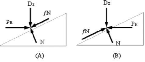
Figure 3 Force diaphragms for the power screw to disengage (A) and engage (B) the clutch
The torque required to move the power screw axially from engaged to disengage is given by:
m xm m
lift xD
d x l d
l d
T
2
(5)
The torque required to move the power screw axially from disengaged to engage is given by:
m xm m
lower xD
d x l d
l d
T
2
(6)
where:
Tlift : Torque for lifting load [Nm] Tlower : Torque for lowering load [Nm] PR : Force required to raising the load [N] P : Force required to lowering the load [N] Dx : Axial force [N] N : Normal force [N] fN : Friction force [N] dm : Mean diameter of power screw [mm] l : Pitch of power screw [mm]
μ : Friction of power screw surface contact
: Lead angle [rad]
C. Modelling of Clutch Linkage
5 5 5 5 4 4 4 4 4 3 3 3 3 3 2 2 2 2 2 1 1 1 , , / , , , , / , , 2 xR S R S S S xR S R S S S X S (7) where:
X1 : Number of revolution of outer power screw S1 : Displacement of inner power screw
S2 : Angular Displacement of clutch fork arm (external)
2 : Angle of Displacement of clutch fork (external) S3 : Angular Displacement of clutch fork arm (internal)
3 : Angle of Displacement of clutch fork (internal) S4 : Angular Displacement of diaphragm spring A
4 : Angle of Displacement of diaphragm spring A S5 : Angular Displacement of diaphragm spring B
5 : Angle of Displacement of diaphragm spring B
D. Modelling of Dry Friction Clutch
Literatures on mathematical models of dry friction clutch engagement have been proposed in many different approaches in [1]-[3] and [6]-[11].
The EMFC uses of a typical dry friction clutch system. This clutch consists of three basic parts. These are the engine flywheel, a dry friction disc and a pressure plate. The flywheel and pressure plate are the driving members. They attach to and rotate with the engine crankshaft. The dry friction disc is the driven member.
In order to investigate the system and to design a controller through analytical procedures, a simplified mathematical model of the typical dry friction clutch which can be thought as a system consisting of two spinning disc models were developed based on paper [2] and [11].
When the clutch is slipping, the differential equations of the clutch engagement system can be expressed as:
cl e e in e
e T b T
I (8)
l v v cl v
v T b T
I (9) where
Ie : Engine inertia,
ωe : The crankshaft rotor speed Tin : The engine torque
be : The crankshaft friction coefficient Tcl : The torque transmitted by the clutch,
Iv : The equivalent vehicle moment of inertia (it takes into account the presence of the clutch, the mainshaft, the powertrain and the vehicle) - which will also depend on the gear ratio
ωv : The clutch disk rotor speed
bv : The corresponding friction coefficient and Tl : The equivalent load torque
Equation (8) models the rotation of the driving members, whereas (9) models the rotation of the driven member. The remaining parts of the power-train system are simply modelled through the equivalent vehicle inertia Iv and the load torque Tl as used in [2]. Based on the clutch geometry and friction characteristics, the clutch torque Tcl is calculated as follows:
2 2
3 3 ) ( . . 3 2 . i o i o v e a cl r r r r R sign R F N T (10) where:
ro : Outer radius of friction plate ri : Inner radius of friction plate
μ : The friction coefficient of the clutch surface material N : The number of friction plate surface
Fa: Normal force applied to the friction clutch R : Equivalent disk ratio
When the clutch is engaged, the angular velocity of the engine and the transmission input shafts are the same. Where
ω= ωe= ωv and the differential equations (8) and (9) become
IeIv
Tin
be bv
Tl
(11)
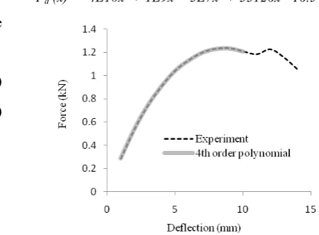
Actually, the normal force is nonlinear function of the clutch mechanical performance. In Figure 4, the load-deflection curve for the diaphragm spring of the EMFC is plotted based on the experimental data. For numerical application, this nonlinear function was approximated by a 4th order polynomial [12] and expressed in terms of the displacement as x
[image:3.595.289.519.399.568.2] [image:3.595.49.290.445.655.2]Fa (x) = -4E10x4 + 1E9x3 - 3E7x2 + 33126x - 16.54 (12)
Figure 4 Loads (kN)-Deflection (mm) Curve for Diaphragm Spring
order polynomial for numerical application based on experimental data. The laboratory test-bench of EMFC is shown in Figure 5 and Figure 6. The laboratory test-bench consists of dry friction clutch and electro-mechanical clutch actuator, engine as power source, water-brake dynamometer as a variable load, torque–speed sensors for measuring engine and output speeds and torques, and data logger systems for recording the data during experiments.
Figure 7 Experimental engagement behaviour of open loop EMFC system
IV. PROPOSED CONTROLLER
Advanced control strategies in many different techniques have been proposed in the literature during standing start to control the dry clutch engagement process, the main objective of those design controllers is to ensure that two fundamental conditions; no-kill conditions and no-lurch conditions have to be satisfied [8] and [9]. The no-kill condition states that the engine stall must be avoided, whereas the no-lurch condition assumes that the unwanted oscillations induced in the power-train should be reduced in order to preserve the driver comfort.
However these requirements are conflicted with a minimum duration of the engagement time like an oscillations induced in the power-train system due to the sudden change of torque within limited of time during the clutch engagement process. Also for an engine could be stalled if an excessively fast engagement process is occurred.
In order to satisfy the different requirements and desire engagement time, this paper proposes a PD controller to control the clutch system for the engagement process because PD controller is quite easy to be achieved and can make the system have excellent performances through optimizing the P and D parameters [13].
Significant efforts have been devoted to providing tuning of PD controller parameters. A method for automatic tuning of simple regulators was introduced in Astrom and Hagglund [14]. The idea was to determine the critical period of waveform oscillation (Tc) and the critical gain (Kc) from a
simple relay feedback experiment and to use Ziegler-Nichols method type of control design method to determine the suitable value of three parameters namely, Kp, Ki, and Kd to satisfy certain control specifications. The block diagram of the proposed controller scheme is given in Figure 8.
Figure 8 Block diagram of the PD controller for DC motor system
A. Parameter tuning for PD controller
The transfer function of a PD controller is given by: s
K + K =
GPD p d
(13) The parallel form of the PD controller has transfer function:
1+T s
K=
GPD p d
(14) The values of critical period of waveform oscillation (Tc) and critical gain (Kc) is determined using Astrom-Hagglund method and will be used in Table 1 in order to obtain the initial parameters of PID controller. Relay feedback is utilized as a controller to the closed loop control system of the DC motor as shown in Figure 9. The period of oscillation attained from a proportional feedback is approximately the critical period. Based on this critical period (Figure 9, [15] and [16]) the critical gain can be derived as follow:
a 4d = Kc
(15)
Figure 9 The relay feedback controller Figure 6 Data logger
system Figure 5 Experimental
Once Tc and Kc values are obtained, the PID parameters (Kp, Ti, and Td) can be specified using Ziegler-Nichols formula (Table 1).
Table 1 Ziegler Nichols parameter tuning. Kp Ti Td
P 0.50 Kc
PI 0.45 Kc 0.85 Tc PI
D
0.60 Kc 0.50 Tc 0.125 Tc
The tuning algorithm proposed in this paper only tunes the proportional gain (Kp) and derivative gain (Kd) of the PID controller. The integration gain (Ki) in this method was not used. There are three reasons why the integration gain was not used [13]. Firstly, it is hard for the integration gain to keep stable the plant having a dead zone which is usually existed in an electrical actuator system. Once the system works in the dead zone, the control signal will be zero. But the integration function makes it impossible, because it will sum up the small error of the dead zone, and give out a control signal. The second reason is the error of this PD control system is not very big because a strong Kpand it is tolerated for an electric actuator used in the EMFC system. For the last one is the PD controller is easy to be realized, and the reliability of the system is much better.
V. SIMULATION AND PERFORMANCE EVALUATION Matlab/Simulink® is used to simulate the mathematical models of the EMFC based on the experimental values as reported in Figure 7. A part of this simulation scheme for EMFC which is the dry friction clutch system used in this work is an evolution that one presented in [11].
In order to avoid the engine stall during standing start scenario, the engagement processes at constant values of the engine speed (at 2500 and 3000 rpm) have been considered [9]. The different engagement behaviours are determined by 10 Nm of the load torque for each constant engine speeds.
The simulation will use parameters of the dry friction clutch system based on medium size car presented in [2]. The DC motor system and the other parts of EMFC models have been both identified from data sheets on the basis of theoretical and physical laws and recognized experimentally. All related parameters have been chosen and shown in appendix (Table 2).
Simulation studies of the proposed PD controller are carried out in order to investigate its effectiveness in this position control. Control performance is determined based on percent overshoot (POS), settling time ts, and steady state error ess of the system.
A closed loop control application incorporating Astrom-Hagglund method based on a relay feedback controller was carried out to attain the critical period of waveform oscillation (Tc) and the critical gain (Kc) which are then used as initial parameter gains for the PID controller. The amplitude of the relay controller is set to 48 since the input voltage is in the range of -24 to +24 volts. From the simulation results, the following parameters Tc, a and d were found to be 0.113 s, 0.141 and 48 respectively (Figure 9). By
using equation (15), the critical gain (Kc) was found to be 432.8. Then, by applying the Ziegler-Nichols formula (Table 1) the values of Kp, Td, and Ti can be obtained.
Finally, the three parameter gains of PID can be specified as follows: Kp = 259.7, Ki = 4596.4, and Kd = 3.7.
From this data, it can be seen that the value of the integral gain (Ki ) is much bigger compare to other gains. Based on the system behaviour performed during relay feedback experiment, a small tolerable steady state error has occurred; therefore the integral gain was not used for controlling this kind of system because the use of big integral gain will make the system unstable.
Figure 10 Output response when the power screw mechanism need to move axially for engagement process
Figure 10 shows the output responses of the controller system. It can be observed that the percent overshoot of the manual tuning of PD controller (about 0.15%) is smaller than that of Ziegler-Nichols auto tuning method (about 2.05%). Thus, PD controller with manual tuning gives better result with good minimum (tolerable) error. However, PD controller with Ziegler-Nichols tuning gives a guidance to attain the initial parameters of PID controller. In terms of percent overshoot and steady state error, both PD controllers with different tunings have good performance.
Figure 11 Engagement speed profiles ofEMFC for different values of engine speed
engagement process and considerably reduce engagement time.
VI. CONCLUSION
Simplified static and dynamic models of a novel Electro-Mechanical Friction Clutch (EMFC) have been developed and presented. The engagement process during standing start scenario for the EMFC has been considered. A Matlab/Simulink® simulation scheme has been built and a control schemes have been implemented and tested within the simulation environment of the EMFC system. Some numerical results of the control engagement process have been evaluated in terms of position control application and its shown improvement achievable by means of the proposed controller. Further optimized by designing and tuning the proposed controller will soon be tested on an EMFC bench-test.
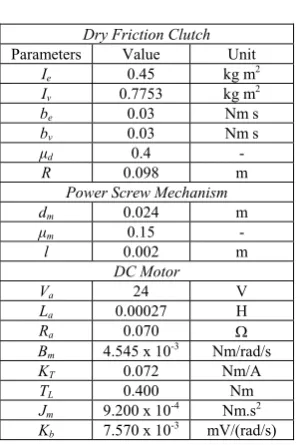
[image:6.595.95.246.306.529.2]APPENDIX
Table 2 Model parameters Dry Friction Clutch
Parameters Value Unit
Ie 0.45 kg m2
Iv 0.7753 kg m2
be 0.03 Nm s
bv 0.03 Nm s
μd 0.4 -
R 0.098 m
Power Screw Mechanism
dm 0.024 m
μm 0.15 -
l 0.002 m
DC Motor
Va 24 V
La 0.00027 H
Ra 0.070
Bm 4.545 x 10⁻³ Nm/rad/s
KT 0.072 Nm/A
TL 0.400 Nm
Jm 9.200 x 10⁻⁴ Nm.s2 Kb 7.570 x 10⁻³ mV/(rad/s)
ACKNOWLEDGEMENT
The authors would like to thank the Malaysian Ministry of Science, Technology and Innovation (MOSTI) and Universiti Teknologi Malaysia (UTM) for their continuous support in the research work. This work was financial supported in part by the Malaysia eSciences Fund under Grant number Vot. 79372.
REFERENCES
[1] Lucente, G., M. Montanari, et al. "Modelling of an automated manual transmission system", Mechatronics 17(2-3): 73-91, 2006.
[2] L. Glielmo and F. Vasca, “Optimal control of dry clutch engagement, “SAE Transactions, Journal of Passenger Cars”, Mechanical Systems, vol. 6, no. 2000-01-0837, 2000.
[3] B. K. Powell, K. E. Bailey, S. R. Cikanek, “Dynamic modelling and control of hybrid electric vehicle powertrain systems”, IEEE Control Systems Magazine, p. 17-33, 1998.
[4] Yamamoto, M, Wakahara, T. Okahora, H. and Oshita, H, “Hydraulic system, shift and lockup controls developed for a large torque capacity CVT”, International Continuously Variable Transmission and Hybrid Transmission Congress, September 23-25.
[5] Kasai, Y. and Marimoto, Y., “Electronically controlled continuously variable transmission (ECVT-II)”, International Congress on Transportation Electronics, 1988, pp. 33-42.
[6] P. Dolcini, C. Canudas de Wit, and H. Bechart, “Improved optimal control of dry clutch engagement,” Proc. of the 16th IFAC World Congress, 2005.
[7] Chiew Y. S., M. Z. Md Zain, K. B. Tawi, S. Ariyono, B. Supriyo and Ng. W. S., “Performance of proportional control in CVT electro–mechanical clutch”, CIM-07, 2007, Johor Bahru. [8] A. Serrarens, M. Dassen, and M. Steinbuch, “Simulation and
control of an automotive dry clutch”, Proc. of the American Control Conference on Boston, Massachusetts, p. 4078 - 4083 vol.5, 2004.
[9] F. Garofalo, L. Glielmo, L. Iannelli and F. Vasca, “Smooth engagement of automotive dry clutch”, Proc. of the 40th IEEE
CDC, pp. 529-534, 2001.
[10] Shuiwen, S., G. Anlin, L.Bangjie, Z. Tianyi and F. Juexin, “The Fuzzy control of a clutch of an electronically controlled automatic mechanical transmission”, JSAE Technical Paper Series, 1995.
[11] “Using simulink and stateflow in automotive applications”, The Mathworks Inc., 1998.
[12] L. Fen, L. Yuxuan, Z. Jianwu and H. Hongcheng, “Robust control for automated clutch of AMT vehicle”, SAE Technical Paper, no. 2002-01-0933, 2002.
[13] J. Cheng, X. Yao, “Control of electric actuator using brushless DC motors and its performance evaluation”, ICICTA'09 Second International Conference Intelligent Computation Technology and Automation, Vol. 3, 10-11 Oct. 2009, pp. 38 – 41.
[14] Åström, K. J. and T. Hägglund, “Automatic tuning of simple regulators with specifications on phase and amplitude margins”, Automatica 20(5): 645-651, 1984.
[15] Hyung-Soo Hwang, Jeng Nae Choi, Won Hyok Lee, Jin-Kwon Kim, “A Tuning for The PID Controller Utilizing Fuzzy Theory”, IJCNN’99 International Joint Conference on Neural Network,1999 Vol. 4,10-16 July 1999, pp. 2210-2215.