Strathprints Institutional Repository
Blair, Steven Macpherson (2013) The Analysis and Application of
Resistive Superconducting Fault Current Limiters in Present and Future
Power Systems. PhD thesis, Electronic And Electrical Engineering. ,
This version is available at http://strathprints.strath.ac.uk/44188/
Strathprints is designed to allow users to access the research output of the University of Strathclyde. Unless otherwise explicitly stated on the manuscript, Copyright © and Moral Rights for the papers on this site are retained by the individual authors and/or other copyright owners. Please check the manuscript for details of any other licences that may have been applied. You may not engage in further distribution of the material for any profitmaking activities or any commercial gain. You may freely distribute both the url (http://strathprints.strath.ac.uk/) and the content of this paper for research or private study, educational, or not-for-profit purposes without prior permission or charge.
Any correspondence concerning this service should be sent to Strathprints administrator:
The Analysis and Application of
Resistive Superconducting
Fault Current Limiters in
Present and Future Power Systems
Steven M. Blair
A thesis submitted for the degree of Doctor of Philosophy to
Department of Electronic and Electrical Engineering
University of Strathclyde
This thesis is the result of the author’s original research. It has been composed by the author and has not been previously submitted for examination which has led to the award of a degree.
The copyright of this thesis belongs to the author under the terms of the United Kingdom Copyright Acts as qualified by University of Strathclyde Regulation 3.50. Due acknowledgement must always be made of the use of any material contained in, or derived from, this thesis.
Abstract
Fault current levels in electrical systems are rising due to natural growth in de-mand, the increasing presence of distributed generation (DG), and increased net-work interconnection. This rising trend is expected to continue in the future. Marine vessel power systems are highly power-dense and are often safety-critical. Power system protection is increasingly challenging in these systems. Supercon-ducting fault current limiters (SFCLs) offer an attractive solution to many of the issues faced.
This thesis establishes and reviews the state of the art in resistive SFCL tech-nology and application knowledge, and provides crucial research-based guidance for the adoption of resistive SFCLs in future power systems.
The issues associated with the application of resistive SFCLs—including lo-cation, resistance rating, the recovery period, and interaction with protection systems—are demonstrated. The relationship between several resistive SFCL design parameters is established using a generic analytical approach, hence pro-viding a framework for validating SFCL designs. In particular, it is shown that a particular SFCL resistance rating leads to a peak in the superconductor energy dissipation, which generally should be avoided.
It is proven that resistive SFCLs have an inverse current-time characteristic, i.e., they will operate in a time that inversely depends upon the initial fault current magnitude. This knowledge is critical for underpinning the operation of a novel protection scheme using multiple resistive SFCLs. The scheme offers several advantages: very fast-acting operation in response to faults anywhere on the system under study; maximum prospective fault currents are prevented from occurring, reducing the duty on circuit breakers; inherent, fast-acting backup; and communications is not required. It is shown that the scheme is suited to highly-interconnected systems with a high presence of DG. The scheme is readily applicable to the design of future utility and marine vessel power systems.
Acknowledgements
I’d like to thank my supervisors, Prof Graeme Burt and Dr Campbell Booth. Their interest and dedication to my research is truly heroic. I’ve got a lot out of the time I’ve spent in our research group, so I’m—retrospectively—immensely grateful for the opportunity to do a PhD at Strathclyde.
I owe a lot of gratitude to others in our research group: Dr Ian Elders, Dr Andrew Roscoe, Dr Stuart Galloway, and Dr Steven Fletcher. There are many others who kept me going, and they know who they are.
Our colleagues at Rolls-Royce provided valuable guidance for my work, and I’d like to thank Chris Bright, Dr Jason Hill, Rob Slater, Jamie McCarthy, and Dr Anita Teo.
A great thanks to Lynsey Connie for her help reviewing my thesis.
I’d especially like to thank my parents, Sam and Linda, for all their support over the years. This thesis is dedicated to them.
Contents
Acknowledgements i
List of Figures x
List of Tables xi
Glossary of Abbreviations xii
1 Introduction 1
1.1 Introduction to the Research . . . 1
1.2 Research Motivation . . . 2 1.3 Principal Contributions . . . 4 1.4 Thesis Overview . . . 5 1.5 Publications . . . 6 1.5.1 Journal Articles . . . 6 1.5.2 Conference Papers . . . 7
2 Review of Developments in Power System Protection 10 2.1 Introduction . . . 10
2.2 Power System Protection . . . 10
2.2.1 Faults . . . 10
2.2.1.1 Arcing Faults . . . 11
2.2.2 Autoreclose . . . 13
2.2.3 Earthing . . . 13
2.2.5 Conventional Protection Functionality . . . 15
2.2.6 Active Protection Research Areas . . . 16
2.3 Typical Utility and Marine Power Systems . . . 17
2.3.1 Utility Distribution Systems . . . 17
2.3.1.1 Increasing DG . . . 17
2.3.1.2 Network Interconnection . . . 19
2.3.1.3 Active Network Management . . . 20
2.3.2 Marine Vessel Power Systems . . . 20
2.3.2.1 The Electric Ship . . . 20
2.3.2.2 Marine Vessel Power System Characteristics . . . 21
2.3.2.3 High Fault Levels . . . 22
2.3.2.4 Other Protection Challenges . . . 24
3 Fault Current Limitation 26 3.1 Conventional Methods of Fault Current Limitation . . . 26
3.1.1 Network Strategies to Limit Fault Levels . . . 26
3.1.1.1 Reduce Network Interconnection . . . 26
3.1.1.2 Increase System Impedance . . . 27
3.1.1.3 Higher System Voltage . . . 28
3.1.1.4 Sequential Circuit Breaker Tripping . . . 28
3.1.2 Non-Superconducting FCL Devices . . . 29
3.1.2.1 Is-Limiters . . . 29
3.1.2.2 Solid State FCLs . . . 29
3.2 Superconducting Fault Current Limiters (SFCLs) . . . 31
3.2.1 Overview of Resistive SFCLs . . . 31
3.2.2 Operation of Resistive SFCLs . . . 33
3.2.2.1 Shunt Impedance . . . 36
3.2.2.2 SFCL Inductance in Superconducting State . . . 37
3.2.3 Benefits of Resistive SFCLs . . . 37
3.2.4 Comparison of FCL Types . . . 39
4 Challenges in the Adoption of Resistive SFCLs 44
4.1 Introduction . . . 44
4.2 Selection of SFCL Location and Resistance . . . 44
4.2.1 SFCL Model . . . 45
4.2.2 Assessment of SFCL Location Strategies . . . 45
4.2.3 Effects of Different SFCL Resistance Values . . . 48
4.2.4 Impact of SFCLs on System Recovery . . . 51
4.2.4.1 SFCL Location A . . . 51
4.2.4.2 SFCL Location D . . . 52
4.2.4.3 System Frequency . . . 54
4.3 Implications for Control Systems . . . 56
4.4 Post-Fault Recovery Time . . . 56
4.5 Effects of SFCLs on Protection . . . 57
4.5.1 Standardisation Work . . . 57
4.5.2 Overcurrent Protection . . . 58
4.5.3 Marine Vessel Protection . . . 60
4.5.4 Distance Protection . . . 60
4.5.5 SFCLs with Autoreclose . . . 61
4.5.6 Other Protection Issues . . . 61
4.6 SFCL Mal-Operation Due to Non-fault Transients . . . 61
4.7 Summary . . . 63
5 Analysis of the Trade-Offs in Resistive SFCL Design 64 5.1 Introduction . . . 64
5.2 Selection of SFCL Resistance by Simulation . . . 65
5.2.1 Resistive SFCL model . . . 65
5.2.2 Comparison of SFCL Energy Dissipation at Different Volt-age Levels . . . 66
5.3 Analysis of Optimal SFCL Resistance Values . . . 69
5.3.1 Analytical Derivation of SFCL Energy Dissipation . . . 69
5.3.3 SFCL with Resistive Shunt . . . 73
5.3.4 Case Study . . . 75
5.4 Relationship of SFCL Energy Dissipation to Minimum Volume of Superconductor Required . . . 77
5.4.1 Comparison with Exponential SFCL model . . . 80
5.5 Relationship to Other Research . . . 81
5.6 Conclusions . . . 82
6 Current-Time Characteristics of Resistive SFCLs 83 6.1 Introduction . . . 83
6.2 SFCL Model . . . 83
6.2.1 Requirements . . . 83
6.2.2 Implementation . . . 84
6.2.3 Example Operation . . . 87
6.3 Analysis of SFCL Current-Time Characteristics . . . 88
6.3.1 Analytical Solution . . . 88
6.3.2 Effect of the AC Point on Wave of Fault Inception . . . 92
6.3.3 Comparison of SFCL and Overcurrent Protection Current-Time Characteristics . . . 94
6.4 Conclusions . . . 95
7 Using Multiple Resistive SFCLs for Fast Fault Detection 97 7.1 Introduction . . . 97
7.2 Principle of Operation . . . 98
7.2.1 Benefits of CDD . . . 99
7.2.2 Advantages of Using SFCLs for CDD . . . 100
7.3 Simulation Models . . . 101
7.3.1 SFCL Model . . . 101
7.3.2 Power System Model . . . 101
7.3.3 Application to Double Circuits . . . 105
7.4 Simulation Results . . . 106
7.4.2 Backup Operation . . . 108
7.4.3 Fault Types and Neutral Earthing Type . . . 108
7.5 Discussion of Potential Issues . . . 110
7.5.1 Comparison with Single Bus-tie SFCL . . . 110
7.5.2 Variable Fault Levels . . . 111
7.5.2.1 Critical Current . . . 112
7.5.2.2 Superconductor Length . . . 113
7.5.3 Mitigating Resistive SFCL Recovery Time . . . 114
7.5.4 High-Impedance Faults and Earth Faults . . . 115
7.5.5 Implications of Several Different Types or Designs of SFCL 116 7.5.6 Application to Networks with Superconducting Cables . . 116
7.6 Conclusions and Recommendations . . . 117
8 Conclusions and Further Work 119 8.1 Conclusions . . . 119
8.2 Further Work . . . 121
8.2.1 Further Analysis of CDD . . . 121
8.2.2 Integrated SFCL Analysis and Design Tool . . . 122
8.2.3 Centralised Protection . . . 122
8.2.4 SFCLs and Arcing Faults . . . 122
8.2.5 Analysis of Characteristics of Different Types of FCL . . . 123
8.2.6 Faster-Acting Backup Protection with Multiple SFCLs . . 123
A Literature Review: Modelling Resistive SFCLs for Power System Applications 124 A.1 Introduction . . . 124
A.2 Simplified Models . . . 124
A.2.1 Without SFCL Recovery . . . 124
A.2.2 With SFCL Recovery . . . 127
A.3 Hardware in the Loop Models . . . 128
A.4 Neural Network Models . . . 129
A.6 Thermal-Electric Models . . . 129
B Analysis of Transient Recovery Voltage with Resistive SFCLs 135 B.1 Introduction . . . 135 B.2 Background . . . 136 B.3 Analysis . . . 136 B.4 Results . . . 138 B.5 Assumptions . . . 140 Bibliography 176
List of Figures
2.1 Arcing fault examples . . . 12
2.2 Typical autoreclose timing for a transient fault . . . 13
2.3 Comparison of system earthing types, shown at generator or trans-former star-point connection . . . 14
2.4 Typical fault current waveform (only phase A shown for simplicity) 15 2.5 Typical two-terminal differential protection arrangement . . . 16
2.6 Distribution system with DG at 11 kV and 33 kV . . . 18
2.7 11 kV distribution system, with potential for increased intercon-nection by closing NOPs . . . 20
2.8 Comparison of marine vessel electrical and propulsion power systems 21 2.9 Typical marine AC electrical system . . . 23
2.10 Short-circuit fault on the 690 V bus . . . 23
3.1 Opening a busbar coupler . . . 27
3.2 Typical resonant fault current limiter [Kar92] . . . 30
3.3 Example three-phase AC resistive SFCL device design [BBE+11] . 33 3.4 Conditions needed for superconductivity [PC98, BHH+11] . . . . 33
3.5 Single-line diagram with resistive SFCL . . . 35
3.6 Resistive SFCL operation . . . 36
3.7 Overview of SFCL projects from [Eck08] . . . 41
4.1 Fault locations, and possible SFCL locations (A, B, C, and D) . . 45
4.2 Typical per phase SFCL resistance characteristic and effect on fault current, for “exponential” SFCL model . . . 46
4.3 Fault current limitation for fault F1 at location A . . . 47
4.4 Total peak fault current for fault F1 . . . 48
4.5 Total RMS break fault current for fault F1 . . . 49
4.6 690 V bus voltage for SFCL location A, for fault F1 (or F3) . . . 52
4.7 Instantaneous real and reactive power delivered by 4 MW generator in the right subsystem for fault F3, with SFCL resistance of 1 Ω . 53 4.8 690 V bus voltage for SFCL location D, for faults F1 and F3 . . . 54
4.9 System frequency for Fault F1 . . . 55
4.10 System frequency for Fault F3 . . . 55
4.11 Transformer inrush current for 350 kVA marine transformer . . . 62
5.1 DG branch with source impedance, transformer impedance, and an SFCL . . . 66
5.2 Energy dissipation and fault current limitation for various SFCL resistance values (at 33 kV side of DG transformer) . . . 68
5.3 Numerical solution of power dissipation, whereRSF CL= 5.0 Ω . . 71
5.4 Derivative of Q with respect toRSF CL, showing a root at ∼18.2 Ω 71 5.5 Total three-phase energy dissipation: exact vs. approximation . . 74
5.6 Variation of SFCL energy dissipation and current limitation (in red/green), with a resistive shunt . . . 75
5.7 Visualisation of results from work in [SH09] . . . 76
5.8 Number of notional superconductor units required for a given level of fault current limitation . . . 80
5.9 Comparison of total energy dissipation between binary and expo-nential SFCL models . . . 81
6.1 Superconductor E-J characteristic (from [PCL+00]) . . . . 85
6.2 SFCL fault current limitation test network . . . 87
6.3 SFCL model response for a three-phase to earth fault . . . 88
6.4 SFCL model current-time characteristics (analysis and simulation). Fault current for DC simulation is the initial fault current from a constant DC voltage source. . . 91
6.5 Effect of current magnitude andα on quench time . . . 93
6.6 Explanation of delay due to fault inception angle . . . 93
6.7 SFCL model current-time characteristics vs. Standard Inverse curve 94 6.8 SFCL design tool . . . 95
7.1 Typical SFCL model current-time characteristics, from method in Chapter 6 . . . 98
7.2 SFCL CDD operation example . . . 99
7.3 Example 11 kV AC distribution system . . . 103
7.4 Fault currents without SFCLs, for three-phase to earth fault at F2 104 7.5 Double circuit application of CDD (in dashed box) . . . 105
7.6 SFCL resistances and currents for three-phase fault at F1 . . . 107
7.7 SFCL 4 and 5 resistances, for three-phase fault at F2 . . . 108
7.8 SFCL backup operation for three-phase fault at F1 . . . 109
7.9 Single bus-tie SFCL location . . . 111
7.10 SFCL 3-5 resistances, for three-phase fault at F2, without the in-coming feeder at SFCL 1 . . . 112
7.11 Incorrect quench of SFCL 3 for Fault 2, during reduced fault level 114 A.1 Typical per phase SFCL resistance characteristic and effect on fault current . . . 126
A.2 Resistance characteristic for the model in [Dud04] . . . 128
A.3 Superconductor E-J characteristic (from [PCL+00]) . . . 131
B.1 Circuit used to examine effect of SFCL on TRV . . . 136
B.2 Effect of SFCL on TRV (analytical and simulated) . . . 138
B.3 System voltage, TRV, and fault current (with and without SFCL) 139 B.4 SFCL located downstream of circuit breaker . . . 140
List of Tables
3.1 Comparison of FCL types . . . 40
4.1 Comparison of impact of SFCL location on fault currents . . . 46
4.2 Comparison of limitation for SFCL location D, for fault F2 . . . . 50
4.3 Comparison of limitation for SFCL location D, for fault F3 . . . . 50
5.1 Power system parameters from multi-objective optimisation in [SH09] 76
6.1 Summary of SFCL model parameters . . . 86
7.1 Summary of power system parameters . . . 102
Glossary of Abbreviations
AC Alternating Current
BSCCO Bismuth Strontium Calcium Copper Oxide CB Circuit Breaker
CIGR´E Conseil International des Grands R´eseaux ´Electriques
CDD Current Division Discrimination CT Current Transformer
DC Direct Current
DG Distributed Generation
EPRI Electric Power Research Institute FCL Fault Current Limiter
FEA Finite Element Analysis
HTS High-Temperature Superconductor HV High Voltage
HVDC High Voltage Direct Current
IEC International Electrotechnical Commission IDMT Inverse Definite Minimum Time
IFEP Integrated Full-Electric Propulsion LV Low Voltage
MV Medium Voltage NOP Normally-Open Point
PSCAD Power Systems Computer Aided Design
RMS Root Mean Square
SFCL Superconducting Fault Current Limiter SSCB Solid State Circuit Breaker
SSSC Static Synchronous Series Compensators TCSC Thyristor-Controlled Series Capacitor
TMS Time Multiplier Setting
TRV Transient Recovery Voltage USD United States Dollar
YBCO Yttrium Barium Copper Oxide VSC Voltage Source Converter
Chapter 1
Introduction
1.1
Introduction to the Research
Power systems are growing and changing significantly. Global demand for electri-cal energy is projected to double by 2050 [Wor07], continuing the trend from the previous 40 years [Int12]. This growth will be caused by an expanding popula-tion [Uni09], improved availability of electricity in developing countries [Wor07], and the increasing electrification of loads such as domestic heating and vehicles [LTHP12]. The importance of using sustainable sources of energy will have a critical impact on future power systems [Mac08b], and is already leading to an increased presence of distributed generation (DG), microgrids, DC systems, and power electronic devices. These developments add further diversity to electrical sources and loads, and thereby complicate the system protection and control.
For future power systems to cater for these fundamental changes, in many cases fault current levels will increase. For example, resiliency against blackouts
is of importance in both grid [PSA+11, AAB+06] and isolated [Mar11] networks.
This, amongst other factors, may necessitate increased electrical network inter-connection, which normally increases fault current levels [Ten10]. The
connec-tion of DG can also significantly increase fault levels [BRB+10, STB+10] and
disrupt protection coordination [DBG+07]. Furthermore, the fault current
[BBE+11, BES+08, FNGB11].
Safe network operation is very challenging in systems with a high fault level. Power system faults can cause significant damage—to life and to equipment—at
the point of fault and to any equipment carrying fault current [BBE+11, MK01].
Circuit breakers must be rated to clear faults for a particular system fault current level; higher fault currents lead to higher circuit breaker costs.
A key solution to these issues is the adoption of fault current limitation in electrical systems. Fault current limiter (FCL) devices typically do not affect power system operation during normal conditions, yet rapidly act to mitigate the destructive and other undesirable effects caused by power system faults. This the-sis examines the application, design parameters, performance, and applicability of resistive superconducting fault current limiters (SFCLs), in both land-based and marine vessel power systems.
1.2
Research Motivation
There is a growing impetus for a “smarter” power grid, with ever greater reliabil-ity and efficiency. The future smart grid should: be built upon sustainable sources of power [Mac08b]; allow increased network interconnection [McN12, Ene11]; al-low flexible and adaptive networks [BC12]; provide better management of power demand [CSI09]; incorporate an increased use of communications and standardi-sation for improved data sharing [BCBB13, EPR11]; and implement faster-acting
power system protection [BES+08].
There are several barriers to this vision:
Power networks need substantial growth, but also need a cost-effective way
to delay or avoid significant upgrades. The prospective long life of power system assets leads to a largely expensive and static infrastructure. For example, for transmission network reinforcement, a 39 GW increase (a 50% increase) in UK generation capacity is expected to cost approximately £8.8bn [ENS12]. Consequently, National Grid Electricity Transmission is
[McG12]. Similarly large investments will be needed by distribution
net-work operators [Ele12], leading to an estimated £53.4bn total transmission
and distribution investment by 2025 [Ofg09].
The UK has the ambitious target of an 80% CO2 emissions reduction by
2050 (relative to 1990 levels) [Cro08], and to achieve this goal significant DG using renewable sources of energy must be installed [Mac08b]. Increased electrical system interconnection can improve the security of supply during periods of generation intermittency which are inherent for many forms of re-newables [Ene11]. Increased interconnection also reduces transmission and distribution losses, supports the system voltage along the length of feed-ers, and provides greater flexibility in the use of available network capacity [McN12]. Despite these benefits, a highly-interconnected power system will typically experience very high fault currents during faults, and faults can affect a greater area of the system. Furthermore, the coordination of pro-tection can be difficult, expensive, or impractical for distribution networks with a high penetration of DG [BG04] and for networks which are highly-interconnected [PI09] because ensuring proper coordination often requires communications for protection signalling.
Full-electric marine vessels and aircraft have increasingly power-dense
elec-trical systems, which leads to extraordinarily high fault currents [BBE+11,
BES+08, FNGB11]. These compact, isolated systems are also particularly
prone to the dangers of arcing faults and blackouts [Mar11, SE12].
There are several instances where circuit breakers in UK distribution
sys-tems are already over-stressed [BRB+10], which limits the network
perfor-mance and flexibility, and prevents the connection of DG—including renew-able sources. Therefore, higher fault levels can result in early obsolescence of existing circuit breakers, as well as incurring the replacement costs or other forms of network reinforcement. The size and weight of circuit breakers are additional constraints for marine vessel, aircraft, and offshore applications. Therefore, in many circumstances fault current levels are already high or are
expected to rise. Conventional methods of reducing fault currents, which include splitting busbars and increasing system impedance, have significant operational shortcomings, such as reduced security of supply for customers or increased sys-tem losses. There has been an increased need for technologies, such as SFCLs, which avoid these issues. Consequently, significant world-wide SFCL develop-ment, including several system trials, has been undertaken over the past decade [NS07, Eck08], particularly in the UK, the USA, South Korea, Japan, Germany, and Italy.
Nevertheless, SFCLs are a relatively new technology and network operators need to understand the best ways to use SFCLs. This thesis provides such guid-ance. In particular, this thesis highlights the challenges with using SFCLs, advises on key SFCL design decisions, and analyses the application of multiple SFCLs in electrical networks, including the relevant control and protection issues.
1.3
Principal Contributions
This thesis provides the following contributions to knowledge:
Investigation and quantification of the challenges involved with the
appli-cation of fault current limitation in power-dense electrical systems.
Evaluation and implementation of appropriate SFCL models for power
sys-tem simulation.
Analysis of the key SFCL design factors which determine the energy
dissi-pation in resistive SFCLs. This affects the SFCL device recovery time and the level of fault current limitation, which are important for grid applica-tions. This work thereby provides a generic methodology for validating the design of a resistive SFCL.
Establishment of the fact that the minimum required volume of
supercon-ductor varies linearly with SFCL resistance but, for a given level of fault current limitation and power rating, is independent of system voltage and superconductor resistivity.
Establishment of the fact that resistive SFCLs intrinsically have inverse current-time characteristics, and analysis of the implications of this for power system protection. This has been achieved through a mathemati-cal derivation and also has been illustrated using simulations.
Design, demonstration, and analysis of a fast fault detection method using
multiple SFCLs. This method can provide the same—or better—performance as unit protection over a wide area, but without the need for communica-tions.
Recommended applications of and caveats with a fault detection method
using multiple SFCLs.
1.4
Thesis Overview
Chapter 2 reviews the relevant background material. The chapter introduces power system protection, and emphasises the challenges with protecting present distribution and marine vessel networks. An overview of FCLs, focussing on resistive SFCLs, is provided in Chapter 3. Chapter 4 builds on this discussion to highlight the challenges related to the application of fault current limitation.
Energy dissipation in resistive SFCLs is investigated in Chapter 5. The im-plications for power system performance, SFCL recovery time, and the volume of superconductor required—and therefore SFCL cost—are analysed.
In Chapter 6, a representative resistive SFCL model is analysed to evaluate its dynamic characteristics during faults. The results are used in Chapter 7 to evaluate a fast-acting method of detecting and isolating faults in electrical sys-tems using multiple SFCLs, without needing communications. The recommended applications and potential disadvantages of this method are explored in detail.
Chapter 8 concludes this thesis by summarising the contributions of the re-search. Further work, which leads on from this thesis, is also suggested.
1.5
Publications
The following publications have been completed during the course of this PhD:
1.5.1
Journal Articles
Measurement of 40 Power System Harmonics in Real-Time on an Economical ARM Cortex-M3 Platform
A.J. Roscoe, G. Oldroyd, T. Sklaschus, S.M. Blair, and G.M. Burt
IET Electronics Letters, volume 49, issue 23, 7 November 2013, p. 1475 - 1476
doi: 10.1049/el.2013.0299
Application of Multiple Resistive Superconducting Fault Current Limiters for Fast Fault Detection in Highly-Interconnected Distribution Systems
S.M. Blair, C.D. Booth, G.M. Burt, and C.G. Bright
IEEE Transactions on Power Delivery, vol. 28, no. 2, pp. 1120-1127, April 2013
doi: 10.1109/TPWRD.2012.2228011
An Open Platform for Rapid-Prototyping Protection and Control Schemes with IEC 61850
S.M. Blair, F. Coffele, C.D. Booth, and G.M. Burt
IEEE Transactions on Power Delivery, vol. 28, no. 2, pp. 1103-1110, April 2013
doi: 10.1109/TPWRD.2012.2231099
Current-Time Characteristics of Resistive Superconducting Fault Current Lim-iters
S.M. Blair, C.D. Booth, and G.M. Burt
IEEE Transactions on Applied Superconductivity, vol. 22, no. 2, pp. 5600205,
April 2012
doi: 10.1109/TASC.2012.2187291
Electrical System
S.M. Blair, C.D. Booth, I.M. Elders, N.K. Singh, G.M. Burt, and J. McCarthy
IET Electrical Systems in Transportation, vol. 1, iss. 3, pp. 93-102, September
2011
doi: 10.1049/iet-est.2010.0053
Analysis of Energy Dissipation in Resistive Superconducting Fault Current Lim-iters for Optimal Power System Performance
S.M. Blair, C.D. Booth, N.K. Singh, G.M. Burt, and C.G. Bright
IEEE Transactions on Applied Superconductivity, vol. 21, no. 4, pp. 3452-3457,
August 2011
doi: 10.1109/TASC.2011.2129518
1.5.2
Conference Papers
Demonstration and analysis of IP/MPLS communications for delivering power system protection solutions using IEEE C37.94, IEC 61850 Sampled Values, and IEC 61850 GOOSE protocols
S.M. Blair, F. Coffele, C.D. Booth, B. De Valck, and D. Verhulst
CIGR ´E Session, Paris, France, 2014 (accepted)
Improving IEC 61850 interoperability and simplifying IED configuration through the standardisation of protection settings
Q. Hong, V.M. Catterson, S.M. Blair, C.D. Booth, A. Dy´sko, T. Rahman
CIGR ´E Session, Paris, France, 2014 (accepted)
Application of Multiple Resistive Superconducting Fault Current Limiters for Fast Fault Detection in Highly-Interconnected Distribution Systems
S.M. Blair, C.D. Booth, G.M. Burt, and C.G. Bright
IEEE Power & Energy Society General Meeting, Vancouver, Canada, 2013
IEC 61850
S.M. Blair, F. Coffele, C.D. Booth, and G.M. Burt
IEEE Power & Energy Society General Meeting, Vancouver, Canada, 2013
Standardization of Power System Protection Settings Using IEC 61850 for Im-proved Interoperability
Q. Hong, S.M. Blair, V. Catterson, A. Dysko, C.D. Booth, and G.M. Burt
IEEE Power & Energy Society General Meeting, Vancouver, Canada, 2013
Demonstration of Adaptive Overcurrent Protection Using IEC 61850 Commu-nications
F. Coffele, S.M. Blair, C.D. Booth, J. Kirkwood, and B. Fordyce
22nd
International Conference on Electricity Distribution (CIRED), Stockholm,
Sweden, 2013
Architecture for Automatically Generating an Efficient IEC 61850-based Com-munications Platform for Rapid-Prototyping of Protection Schemes
S.M. Blair, C.D. Booth, and G.M. Burt
PAC World Conference, Dublin, Ireland, 2011
The Use of Real Time Digital Simulation and Hardware in the Loop to De-Risk Novel Control Algorithms
S. Loddick, U. Mupambireyi, S.M. Blair, C.D. Booth, X. Li, A.J. Roscoe, K. Daffey, and J. Watson
European Conference on Power Electronics and Applications, Birmingham, UK,
2011
The Use of Real Time Digital Simulation and Hardware in the Loop to De-Risk Novel Control Algorithms
S. Loddick, U. Mupambireyi, S.M. Blair, C.D. Booth, X. Li, A.J. Roscoe, K. Daffey, and J. Watson
IEEE Electric Ship Technologies Symposium, Alexandria, Virginia, USA, 2011 doi: 10.1109/ESTS.2011.5770869
Investigation of Superconducting Fault Current Limiter Application in a Power-Dense Marine Electrical Network
S.M. Blair, N.K. Singh, I.M. Elders, C.D. Booth, G.M. Burt, and J. McCarthy
The 5th
IET International Conference on Power Electronics, Machines and Drives
(PEMD), Brighton, UK, 2010
doi: 10.1049/cp.2010.0024
Implications of Fault Current Limitation for Electrical Distribution Networks S.M. Blair, A.J. Roscoe, C.D. Booth, G.M. Burt, A. Teo, and C.G. Bright
The 10th
IET International Conference on Developments in Power System
Pro-tection (DPSP), Manchester, UK, 2010
doi: 10.1049/cp.2010.0355
Benchmarking and Optimisation of Simulink Code Using Real-Time Workshop and Embedded Coder for Inverter and Microgrid Control Applications
A.J. Roscoe, S.M. Blair, and G.M. Burt
Proceedings of the 44th
International Universities Power Engineering Conference
(UPEC), Glasgow, UK, 2009
Operational Control and Protection Implications of Fault Current Limitation in Distribution Networks
S.M. Blair, N.K. Singh, C.D. Booth, and G.M. Burt
Proceedings of the 44th
International Universities Power Engineering Conference
Chapter 2
Review of Developments in
Power System Protection
2.1
Introduction
This chapter reviews the background material which is relevant to the contri-butions of this thesis. The chapter begins by introducing the topic of power system protection, and hence establishes the motivation for curtailing the dan-gerous and costly effects of power system faults. Section 2.3 illustrates typical utility and marine vessel electrical systems—two key applications for fault current limitation—to highlight the main challenges associated with their operation.
2.2
Power System Protection
2.2.1
Faults
Faults can occur in power systems due to a variety of causes, including [IEE01]:
Lightning strike to an electrical tower or to overhead lines.
Tree branches touching overhead lines, due to weather or overgrowth.
Wildlife coming into contact with equipment, such as transformer bushings.
Accidental damage to underground cables, caused by utility maintenance
personnel or by construction activities.
Internal faults within generators, transformers, or other primary equipment,
due to aging, moisture, or breakdown of insulation.
Overvoltages due to electrical switching transients.
Faults in three-phase AC power systems are usually classified as one of the following: single-phase to earth; phase to phase; or three-phase (a “balanced” fault). Phase to phase and three-phase faults may or may not involve contact with earth. Another possible fault type is an open phase, which can be caused by a break in a conductor [IEE01]. It is also possible for one type of fault to develop into another type over time [MK01]. For example, a single-phase to earth fault may evolve into a phase-earth-phase fault [Lou10]. If the path of fault current flows through an external impedance, such as through a tree branch to earth, then this impedance is known as the fault impedance. A fault with negligible fault impedance is normally referred to as a short-circuit.
Faults can also be classified as being transient (e.g., caused by a lightning strike), permanent (e.g., a break in an underground cable), or semi-permanent (e.g., a tree branch across conductors which “burns-out” after sufficient fault current has passed through). Approximately 80-90% of faults on overhead lines are transient [Als11], and approximately 85% of faults are single-phase to earth [Cof12].
2.2.1.1 Arcing Faults
Most faults will include arcing at some stage, typically at the point of fault and between the contacts of the circuit breaker which isolates the fault [MK01]. An arc is a “cloud” of vaporised conductor which forms an ionised plasma, allowing current to pass through a dielectric material. An arc is initiated when there is sufficient ionisation of the air gap (or any dielectric medium) between two
(a) Evidence of vaporised conductor due to an arcing fault on a marine vessel transformer [Daf09]
(b) 480 V arc flash experiment [Sho11]
Figure 2.1: Arcing fault examples
conductors such that their voltage difference exceeds the dielectric breakdown voltage. There are many dangers associated with arcing faults, including:
High risk to human life: burns, damage to eyesight and hearing due to
intense pressure waves, permanently impaired balance, and loss of sense of smell [IEE02].
Vaporised conductor (see Figure 2.1a) leads to very high temperatures (up
to 20,000◦C [Lee82]), and gaseous copper, for example, expands in volume
by a factor of 67,000 compared to solid copper [Lee87]. This can cause fires and severe damage to other equipment, as illustrated in Figure 2.1b.
Due to the relatively low fault current, arcing faults can be difficult to
detect, or can result in relatively long clearance times if time- and current-graded overcurrent protection is used [Lou10]. Therefore, if allowed to persist without interruption by a circuit breaker or otherwise, an arcing fault may develop into a more serious short-circuit fault. Furthermore, a long-lasting, low-current fault may cause more total damage than a short-circuit fault, which would be cleared by overcurrent protection relatively quickly [Lou10].
Figure 2.2: Typical autoreclose timing for a transient fault
2.2.2
Autoreclose
Autoreclose systems are commonly used to mitigate transient faults, which may include arcing at the point of fault [Als11]. After opening a circuit breaker to clear a fault, the circuit breaker is held open for a period of time, known as the dead time. The dead time allows for de-ionisation of the air gap at the fault location (or, if single-pole autoreclose is used, the dead time must also allow for the secondary arc to extinguish [Web95]). Following the dead time, the circuit breaker is reclosed to attempt to restore the supply of power. This process is illustrated in Figure 2.2.
If the fault is still present after reclosing—indicating a permanent fault—the circuit breaker will be opened and locked-out until the fault is repaired. Multi-shot autoreclose schemes involve two or more reclose stages, which can be useful for “burning-out” semi-permanent faults [Als11], but this approach has associated safety risks.
2.2.3
Earthing
The effects of faults in power systems will depend significantly on the system earthing scheme used [IEE01]:
Solidly-earthed neutral.
Resistance-earthed neutral.
Inductance-earthed neutral, commonly known as a Petersen coil, or
Figure 2.3: Comparison of system earthing types, shown at generator or transformer star-point connection
Unearthed neutral, or isolated.
These earthing types are compared in Figure 2.3. In general, impedance-based earthing can significantly reduce the fault current experienced during earth faults. Unearthed systems are susceptible to transient overvoltages, particularly during single-phase to earth faults.
2.2.4
Calculating Fault Levels
The term “fault level” is used to express the prospective maximum effect of a fault at a particular location in a power system. It is typically given as a current value (in kA), or as a power rating (in MVA) at an associated voltage level. For example, typical maximum distribution system fault levels in the UK are 250 MVA at 11 kV, and 750-1000 MVA at 33 kV [Sco07, Ele10].
The IEC 60909 standard [IEC01] establishes methods for calculating fault currents in three-phase AC power systems, and defines naming conventions. The peak short-circuit current is the maximum instantaneous fault current experi-enced during a spontaneous short-circuit, or when a circuit breaker is closed onto a faulted circuit [Gri09].
Figure 2.4 illustrates a typical fault current waveform, for a single phase.
Due to the nature of switching events in a (predominantly) RL-circuit, the fault
current contains both an AC component and a decaying DC component. The magnitude of the DC component depends upon the current phase angle and the point on wave of fault occurrence, relative to the pre-fault voltage waveform. The DC decay time depends upon the system X/R ratio; a larger X/R ratio
Figure 2.4: Typical fault current waveform (only phase A shown for simplicity)
leads to a longer decay time. The steady-state, or symmetrical, fault current value includes only the AC component, which is the value of fault current likely to be experienced when opening a circuit breaker.
In general, for three-phase faults, a power system can be simplified as a single-line diagram, with the fault current expressed as a differential equation, given by Equation 2.1 [Duf03]:
ˆ
V sin(ωt+α) = i(t)R+Ldi(t)
dt (2.1)
where ˆV is the peak phase voltage, R and L are the resistive and inductive
components of the system impedance, respectively, and i(t) is the instantaneous
phase current.
2.2.5
Conventional Protection Functionality
The role of power system protection is to detect and isolate faults. Clearly, this must be done for safety reasons, but protection is also needed to minimise the damage to power system equipment, and therefore to minimise the cost and duration of repairs. Protection systems should ensure that the minimal number of power consumers are affected by faults and, in the most extreme cases, protection aims to prevent wide-scale disruption or even blackouts in the power system.
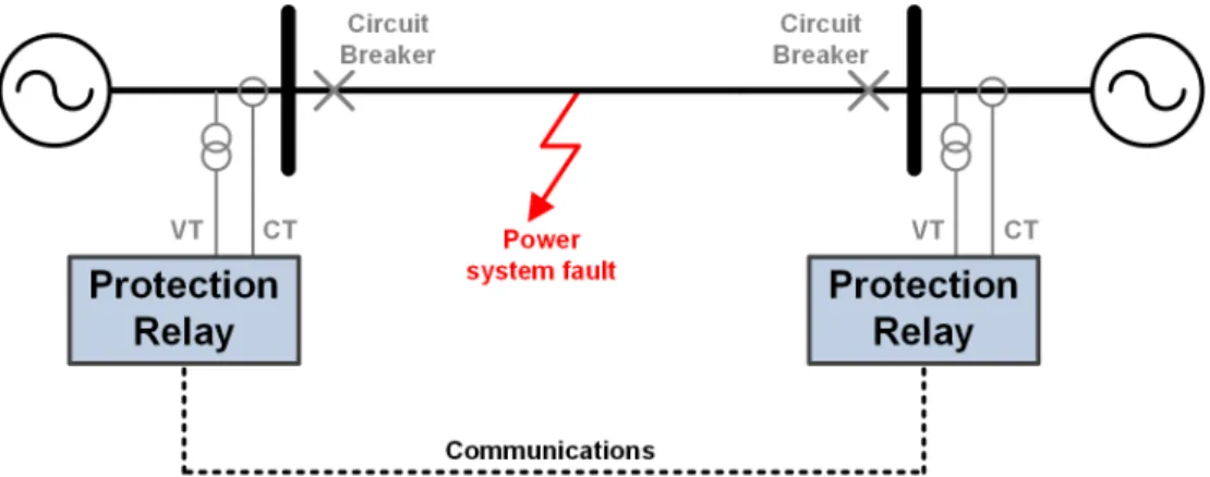
measure-Figure 2.5: Typical two-terminal differential protection arrangement
ments, a protection relay, and one or more circuit breakers, as shown in Figure 2.5. There are several types of well-established protection functions, including: phase overcurrent, earth fault overcurrent, distance, differential, and loss of mains (which includes a variety of methods, such as or over-voltage, and under-or over-frequency [ENA10]). Multiple protection devices must be properly counder-or- coor-dinated, or graded, to ensure correct and timely isolation of faults at any location throughout a power system.
2.2.6
Active Protection Research Areas
Several specific areas within power system protection are presently the subject of significant research:
Communications is becoming increasingly important to the operation of
modern and emerging protection and control schemes, particularly for
man-aging the impact of DG [TLY09] and low voltage microgrids [Laa10, CSRAGB+12],
for enabling fast-acting protection and restoration [YAA+02, BES+08, PSA+11],
and for ensuring wide-area integrity of a power system [AAB+06]. IEC
61850 is an international standard which offers several benefits to these schemes, such as: high-speed Ethernet communications, a standardised data model, a formal configuration language, reduced life-cycle costs, and interoperability [Bra04, Mac06].
changes in the electrical system. It is particularly relevant for networks with DG (see Section 2.3.1.1), for permitting islanding, and where Active Network Management (ANM) schemes may dynamically alter the electrical
system topology [BC12, CBB+13].
DC systems are of interest for several power system applications, including:
relatively compact microgrid, marine vessel, and aircraft power systems [XC11]; long-distance HVDC transmission lines; and for interfacing non-synchronous sources of generation to AC systems. Protection of DC systems involves major challenges, such as the lack of a current zero-crossing for interrupting fault currents, the extremely high transient fault currents due to the discharge of capacitive filters on voltage source converters [Fle13],
and the detection of faults in multiterminal systems [YFO10, FNG+12].
2.3
Typical Utility and Marine Power Systems
This section provides a summary of typical utility (i.e., land-based) distribution and marine power systems in use today, and the main protection and other op-erational challenges.
2.3.1
Utility Distribution Systems
Distribution systems are evolving in a number of ways, as described in the fol-lowing subsections.
2.3.1.1 Increasing DG
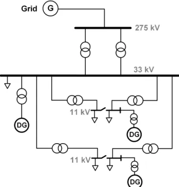
There is an increasing presence of DG in distribution networks, as illustrated in Figure 2.6. DG can offer several benefits, such as voltage support, reduced electrical network losses, and the inherent environmental benefits from connecting renewable forms of generation. Nevertheless, DG can lead to increased fault levels at the point of connection, bi-directional power flows, and the potential for islanded operation. Each of these factors has a consequent impact on protection:
Figure 2.6: Distribution system with DG at 11 kV and 33 kV
Increased DG has the potential to significantly increase fault current levels
[SB07, Neu07]. In some cases, circuit breakers in the UK’s distribution sys-tem are already stressed beyond their current breaking capability (requiring restricted network operation to alleviate the fault level constraint), and it has been shown that growth in DG may result in 1-6% of all distribution circuit breakers in the UK failing to meet prospective fault current levels
[BRB+10]. This rise in fault levels must be dealt with in a cost-effective
manner.
Some forms of DG—such as photovoltaics, wind turbines, and fuel cells—are typically grid-connected via power electronic converters. To avoid damage to the internal semiconductor devices, converters must limit their fault cur-rent contribution to approximately 1-2 pu of their rated curcur-rent output; these forms of DG therefore have a lower impact on fault current levels than directly-connected synchronous machines. A very high penetration of asynchronous generation could, overall, significantly reduce fault levels in the UK [Nat12].
Several protection issues can arise due to relatively high levels of DG pen-etration, and the consequent opportunity for bi-directional power flows. These issues include false tripping of overcurrent relays for faults on adja-cent feeders, protection blinding (where DG supports the system voltage during a fault, and thereby delays or blocks network protection due to the lower grid fault current contribution), and disruption of the grading between multiple overcurrent relays [BD00, Cof12].
Islanding is not normally permitted within utility distribution systems.
This is due to the issues involved with ensuring that the islanded sys-tem’s voltage and frequency remain stable, and due to the difficulties in-volved with detecting faults in both islanded and grid-connected conditions [Cof12, BCBB13]. Presently, each DG owner must implement loss of mains protection to ensure that generators are tripped off in the event of
discon-nection from the grid [DBG+07]. Nevertheless, islanding may be permitted
in the future to improve the security of supply for customers.
2.3.1.2 Network Interconnection
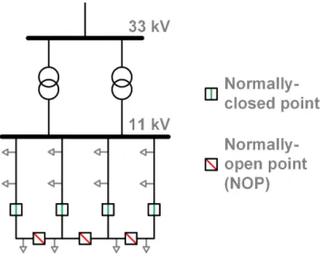
There is a desire to increase network interconnection to improve voltage support, increase the available network capacity (and to allow more flexibility in the con-nection of large loads), reduce losses, and improve power quality [Ada06, McN12]. Furthermore, the connection of intermittent, renewable DG—such as wind— demands greater interconnection at both distribution and transmission levels to ensure adequate security of supply. In distribution networks, particularly at 11 kV in the UK, increased interconnection can be achieved by closing normally-open points (NOPs), as illustrated in Figure 2.7.
DG connected via power electronic converters can also inject additional har-monics into the AC power system due to their non-linear nature. This reduces power quality, leading to issues such as increased transformer losses [IEE93, Mas04]. Interconnection can mitigate this because lowering the system impedance reduces the voltage harmonic distortion resulting from non-linear currents.
Figure 2.7: 11 kV distribution system, with potential for increased interconnection by closing NOPs
The protection issues associated with allowing electrical “loops” must be con-sidered. In many cases, differential protection, and the associated communica-tions, is required [Sco07].
2.3.1.3 Active Network Management
ANM schemes can provide flexible, optimised operation of distribution systems. For example, ANM can facilitate the operation of networks with DG, by ensuring that constraints in fault levels (often referred to as Fault Level Management), line thermal ratings, and voltage profiles are met [MAC08a, Cof12]. Greater DG penetration is thereby possible. ANM schemes can also be used to minimise network losses, manage energy storage, and provide post-fault restoration.
2.3.2
Marine Vessel Power Systems
2.3.2.1 The Electric Ship
There has been significant motivation for full-electric designs of marine vessels [HM95], commonly referred to as Integrated Full-Electric Propulsion (IFEP)
[NBS+06]. In these systems, propulsion is provided via electric motors, and all
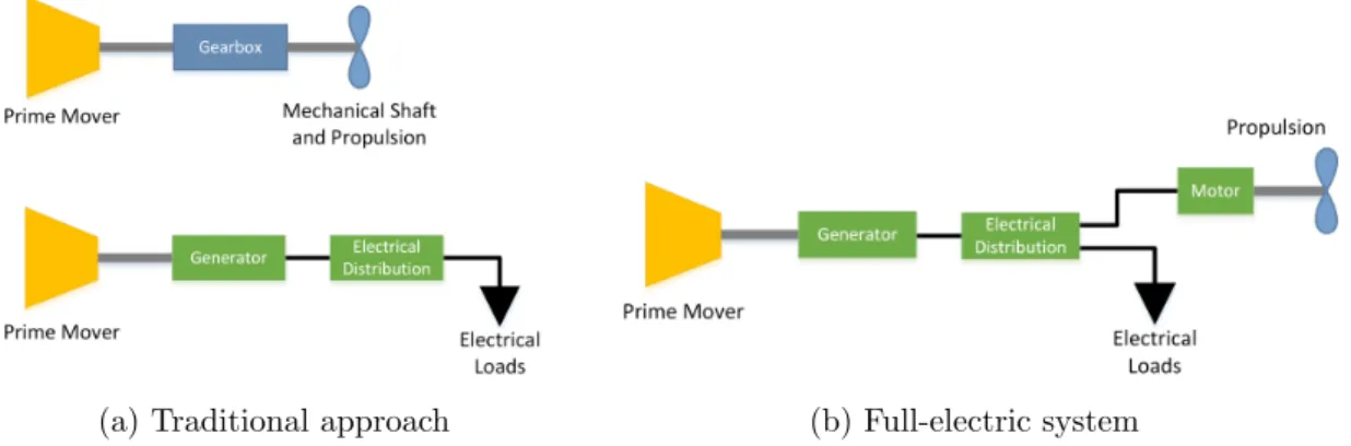
of the vessel’s electrical loads share the same power distribution system. This is compared with the traditional approach in Figure 2.8.
(a) Traditional approach (b) Full-electric system
Figure 2.8: Comparison of marine vessel electrical and propulsion power systems
There are several benefits to full-electric vessel design, including [KR02, BES+08]:
Reduced fuel use, particularly throughout the lifetime of the vessel. The
unified power system allows for prime movers to be dispatched and loaded efficiently.
Reduced space and weight requirements, because fewer generators may be
needed.
Greater flexibility in the vessel’s layout, because prime movers do not need
to be adjacent to propulsion devices (or coupled by long rotating shafts). Furthermore, a greater number of smaller propulsion devices can be used to improve the vessel’s maneuverability.
2.3.2.2 Marine Vessel Power System Characteristics
Marine vessel power systems have the following characteristics:
The “survivability” of the vessel is critical, particularly for naval vessels. A
blackout of the power system can result in loss of propulsion, and therefore loss of control of the vessel. Electrical faults, particularly arcing faults, present a substantial risk to the operation of IFEP systems. Consequently,
the electrical system must be designed for reliability [SEB+07], and DC
zonal architectures have been proposed to provide greater redundancy and survivability [RBD11].
Marine vessels need to support highly flexible levels of load, particularly for “cruise” and “boost” propulsion modes [HM95]. In some situations, the load, and the connected generation, may be as low as 10% of the full
rated value [BES+08]. Vessel operations such as dynamic positioning (DP)
[Rad08] and Replenishment at Sea (RAS) can involve both cyclicly varying
and regenerative motor loads [ENS+07, Eld11].
The presence of power electronic converters with high power ratings leads
to severe distortion of current and voltage [SE08]. In many cases, harmonic
filters are needed [CMP+07, SNG+08], with the consequent cost, weight,
and space requirements, and safety issues [Mar11].
Relatively low voltages must be used, typically no higher than 11 kV. The
preference for use of low voltage marine electrical systems is driven by the costs of increased insulation associated with higher voltages, employing crew with particular operating qualifications, and increasingly stringent safety regulations.
2.3.2.3 High Fault Levels
Marine vessel electrical systems, by design, are very power-dense—in some cases
with over 100 MW of generation onboard [BES+08, Roy13]. The UK Royal Navy
is scheduled to become the UK’s largest independent power producer by 2022, at 1.2 GW combined [Daf09]. Such power-dense, low voltage systems have the potential for extremely high fault currents [HB06].
Figure 2.9 illustrates the electrical system for a typical offshore anchor han-dling/supply vessel. The vessel under consideration has six synchronous diesel generators, four 2.1 MW and two 4 MW units. The 4 MW generators are asso-ciated with local propulsion and thruster motors; they are also connected to the main switchboard and are therefore capable of supplying other non-propulsive loads. The motor-generator set provides the capability for providing improved power quality—such as constant 60 Hz, 230 V output—to some 230 V loads, despite moderate variations in frequency and voltage at the 690 V switchboard.
Figure 2.10 illustrates the fault current for a short-circuit fault at the main 690 V busbar (at the location indicated in Figure 2.9).
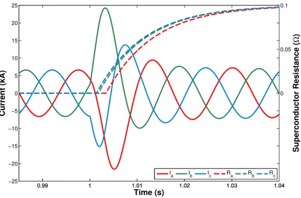
Figure 2.9: Typical marine AC electrical system
0.99 1 1.01 1.02 1.03 1.04 1.05 1.06 1.07 1.08 1.09 −250 −200 −150 −100 −50 0 50 100 150 200 250 Time (s) Current (kA) Phase A Phase B Phase C
Figure 2.10: Short-circuit fault on the 690 V bus
ex-cessively high. The difficulty in procuring suitably rated circuit breakers1 requires that the fault level must be reduced by, for example, splitting the electrical system (by opening the bus-tie circuit breakers) or inserting current-limiting reactors. These measures place operational restrictions on the vessel, such as preventing safely powering the entire system using a single generator in some circumstances; these restrictions can also reduce the security of supply.
Furthermore, high fault currents impose severe stress due to heating and elec-tromagnetic forces [HB06, Daf09, MK01] on any equipment carrying fault
cur-rent, including switchgear, cables, busbars, and transformer windings [BHH+11].
Cables must be mechanically braced to cope with the electromechanical forces [Daf09]. There is also an increase in arc incident energy [IEE02], and therefore a greater arc flash hazard, associated with higher fault currents [Bla10]. Arc flash hazard is of particular concern in marine vessels due to the confined spaces and the potential for toxic fumes [IMa11].
2.3.2.4 Other Protection Challenges
The requirements for marine protection schemes are even more stringent than for
utility systems. Marine protection systems must [BES+08]:
Be fast-acting to minimise the risk of a fault developing into a system-wide
blackout.
Operate only for faults in the desired area (unless for backup).
Operate only the minimum number of circuit breakers needed to isolate the
fault.
Have backup protection, but which operates only if the primary protection
fails.
Adapt to highly variable fault levels, due to the large variation of load and
connected generation.
1For example, reference [GE 13] reports a peak current rating of 108 kA and a maximum
symmetrical breaking capability of approximately 40 kA RMS for 38 kV circuit breakers, and 63 kA for 15 kV circuit breakers. This is in accordance with the preferred ratings in ANSI C37.06-2000 [ANS00, Ada06]
Traditional overcurrent protection systems may be ineffective at detecting faults in all vessel operating conditions, due to the highly variable fault levels [SBBM07]. The impedances of the electrical system are typically very low due to the short cable lengths. Distance protection and current-graded overcurrent protection are impractical in these circumstances [TM06].
Chapter 3
Fault Current Limitation
References [Ada06, NS07, MF07, Eck08, Uni11] provide excellent reviews of the various methods and technologies for limiting fault currents. Section 3.1 sum-marises the main conventional methods, and Section 3.2 examines SFCLs in de-tail.
3.1
Conventional Methods of Fault Current
Limitation
3.1.1
Network Strategies to Limit Fault Levels
Network operators can use several techniques to minimise fault levels. The rela-tive merits of each method are discussed in the following subsections.
3.1.1.1 Reduce Network Interconnection
The network topology can be changed to a configuration with a lower fault current level. Typically, this involves splitting barbars by opening a busbar sectionaliser or bus coupler, as illustrated in Figure 3.1.
Figure 3.1: Opening a busbar coupler
This technique reduces the security of supply because it tends to separate sources from loads, increases losses, reduces voltages, and reduces grid flexibility. It can also be expensive to implement if, for example, a busbar sectionaliser does not already exist. If the busbar must be re-coupled to, for example, disconnect a supplying transformer for maintenance, generation may need to be curtailed during this period to ensure that the fault level remains within the breaking capability of the available switchgear [EA 03].
Similarly, normally-open points can be moved, such that new DG connec-tions are made at a location with higher impedance, due to the greater electrical distance between the generator and the substation.
3.1.1.2 Increase System Impedance
Air-cooled reactors or transformers with relatively high reactance can be installed to increase the system impedance. Reactors are most commonly installed between two busbar sections [KK09]. However, increasing the system impedance leads to the following disadvantages:
Capital expenditure for the additional equipment. However, reactors may
be easier to install and operate (although they are often very large [EA 03])
and may be cheaper than SFCLs [KYT+05].
Undesirable continuous power losses, hence increasing network operational
costs [Ada06].
Power quality issues, such as increased voltage harmonic distortion and
drop across the additional impedance [Cer99]. This is highly undesirable in present and future networks [SB07].
Assuming the fault level increase is the result of increased DG, these disad-vantages may lead to a sub-optimal supply to customers during periods where the DG is disconnected [EA 03].
Current-limiting reactors have been installed in marine vessels, such as for limiting DC current on the RMS Queen Mary 2 [Mar11].
3.1.1.3 Higher System Voltage
Higher voltage levels, where possible, can be introduced to reduce currents [Ada06]. Due to the greater cost of high voltage equipment, this option is unsatisfactory in many cases. Furthermore, this option is also not likely to be applicable to existing systems, and other methods of fault current limitation must be considered.
3.1.1.4 Sequential Circuit Breaker Tripping
Sequential circuit breaker tripping is a protection scheme which typically involves opening an upstream circuit breaker, relatively far from the fault, that is rated to handle the maximum prospective fault current. A downstream circuit breaker (ideally, the circuit breaker nearest the fault), which has a much lower rating and is cheaper, can then be opened due to the reduced, or zero, current flow. Finally, the upstream circuit breaker is re-closed.
This scheme increases the overall time required for fault clearance and load restoration. Opening an upstream breaker causes disruption to a wider area of the network (including non-faulted zones) than a downstream breaker located closer to the fault.
A similar approach, which may avoid expensive circuit breaker upgrades, in-volves tripping a contributor to the fault current (such as DG) to reduce the fault current such that the fault can then be cleared by the appropriate circuit breaker [EA 06]. However, fault clearance times are increased, tripping the sources of sup-ply is undesirable, communications may be needed, and the safety repercussions are severe if the scheme fails.
3.1.2
Non-Superconducting FCL Devices
3.1.2.1 Is-Limiters
Is-limiters (where Is stands for “short-circuit current”) are devices which quickly
route fault current through a high-impedance shunt or a current-limiting fuse, by detonating a small explosive charge. This process must be initiated by fault detection circuitry. It is particularly attractive for MV systems with high prospec-tive fault currents, as a cost-effecprospec-tive and faster-operating alternaprospec-tive to a circuit
breaker [SSM+05]. At present, devices are available to interrupt a symmetrical
fault current of up to 300 kA at 15.5 kV [Aar13]. Over 2,500 devices are in operation throughout the world [Har12] and have been required for naval vessel
systems [SSM+05].
However, there are concerns if the device fails to operate; the probability of
failure to operate has been estimated at 1 in 1.75 x 10⁻³ [Par04]. The cost of
an Is-limiter is comparable to an equally-rated circuit breaker, but Is-limiters
are restricted to a single-use, require isolators (at additional cost) for safe re-placement, require a special enclosure in the substation [EA 03], and the fault current triggering threshold cannot easily be varied after deployment. The use
of Is-limiters could increase customer interruptions and customer minutes lost if
nuisance-tripping occurs.
3.1.2.2 Solid State FCLs
There are several methods for limiting fault currents using power electronic de-vices:
As described in Section 2.3.1.1, converter-interfaced generation will
inher-ently limit its contribution to fault current.
Solid state circuit breakers (SSCBs) use power electronic switches to quickly
interrupt fault currents. Nevertheless, SSCBs based on insulated-gate bipo-lar transistors (IGBTs) have relatively high on-state losses of approximately 1% of the rated load power during normal operation [APRP06]; switches
based on thyristors can have lower losses and faster switching [MF07]. Varis-tors are needed to prevent overvoltages across the IGBTs or thyrisVaris-tors due
to the highLdidt experienced during current interruption [MF07]. At present,
few devices are commercially available, particularly at high fault current ratings [Fle13]. The devices have a high cost and low reliability [Neu07].
Thyristor-controlled series capacitors (TCSCs) can be used to provide both
series compensation during normal conditions, and fault current limitation during faults. As shown in Figure 3.2, thyristors (or gate turn-off thyristors)
can be controlled to insert a resonantLC circuit, which is tuned to impede
current at the fundamental power system frequency. A mechanical circuit breaker can thereby more easily isolate the fault due to the reduced fault current. Typically, fault detection circuitry is required, although passively-triggered devices have been proposed [GF12]. Due to the cost of TCSCs, their use for fault current limitation is mainly applicable if a TCSC device already exists for series compensation.
Thyristor 1
Thyristor 2 L
C
SW1 SW2
Figure 3.2: Typical resonant fault current limiter [Kar92]
Static synchronous series compensators (SSSCs) are used to control real
and reactive power flows and to dampen power swings in transmission lines, by injecting voltages using a voltage source converter [DMTH00, The13]. Similarly to TCSCs, using SSSCs for fault current limitation is only recom-mended if the device already exists in the system [MF07].
3.2
Superconducting Fault Current Limiters
(SFCLs)
Superconductivity was first discovered by Kamerlingh Onnes in 1911 [Sta02], where mercury was found to have zero electrical resistance at temperatures be-low 4 K. There are several attractive applications of superconductivity in power systems, including transmission cables, transformers, magnetic energy storage, and electrical machines [Sta02]. The first superconducting fault current lim-iters (SFCLs) were proposed in the 1970s [GF78], and significant research and development has been undertaken, particularly since the discovery of so-called high-temperature superconductors (HTS) in 1986. HTS materials typically per-mit liquid nitrogen to be used for cooling the superconductor, rather than a more costly cryogen such as liquid hydrogen.
Several types of SFCL have been proposed, but this thesis focuses on the application of resistive SFCLs, as described in Section 3.2.1. For context, Sec-tion 3.2.4 describes and compares the other main types of SFCLs. Appendix A discusses the modelling of resistive SFCLs in detail.
3.2.1
Overview of Resistive SFCLs
Resistive SFCLs are the simplest and most obvious form of SFCL, because the superconductors are electrically in series with the phase conductors. Resistive SFCLs operate on the principle that passing a current, which is greater than
the superconductor’s rated critical current, Ic, through a superconducting wire
initiates “quenching” and results in a transition to a resistive state [HB06, NS07, BSBB09]. Hence, there are virtually no electrical losses in the SFCL during normal operation, yet an SFCL intrinsically inserts impedance into the fault current path during a fault, as long as the transition threshold conditions are satisfied. Nevertheless, the superconductors may experience AC losses [Sta02] (if carrying AC), and there are power losses associated with the operation of the cryogenic system, mainly due to heat loss from the current leads which connect
the external power system to the superconducting element(s) [CK13]. Cryogenic
losses are especially problematic at lower temperatures [BHH+11] and thereby
have a significant bearing on SFCL design.
SFCLs are not restricted to a single current-limiting operation, but usually
require a recovery period after operation, ranging from several seconds [GRS+99]
to several minutes [NS07], during which the superconducting element is cooled until it returns to its superconducting state. In general, SFCLs are a much more favourable solution to addressing high fault levels than the traditional solutions discussed in Section 3.1, all of which have a number of operational and safety-related disadvantages. The operation of resistive SFCLs is described in more detail in Section 3.2.2.
Several superconductor materials have been used for resistive SFCLs, includ-ing Bismuth Strontium Calcium Copper Oxide (BSCCO), Yttrium Barium
Cop-per Oxide (YBCO), and Magnesium Diboride (MgB2). BSCCO is considered a
first generation (1G) HTS material, whereas 2G materials such as YBCO offer higher critical current values for a given wire radius, particularly under an ex-ternal magnetic field, and provide better mechanical stability. Superconductivity
in MgB2 was discovered in 2001, and the material is of interest due to its
rela-tively low cost (approximately 2-3 USD/m) and due to its mechanical robustness
[BHH+11]. However, MgB
2 has a relatively low critical temperature of 39 K,
compared with 90 K for YBCO and 110 K for BSCCO.
A cross-section of a resistive SFCL device developed by Applied Superconduc-tor Ltd., and deployed for testing in Lancashire, UK in 2009, is given in Figure 3.3
[BBE+11]. Each phase of the device consists of several superconducting “tubes”
suspended in the cryogenic chamber. Each tube is made from BSCCO-2212 bulk
Figure 3.3: Example three-phase AC resistive SFCL device design [BBE+11]
3.2.2
Operation of Resistive SFCLs
Ic1 Ic2 0Hc1 0Hc2 T c Resistive State Current (A) Temperature (K) Magnetic flux (T) Flux-flow State Flux-creep StateAs depicted in Figure 3.4, superconductors remain in the superconducting state whilst three conditions are met:
1. The temperature is below the critical temperature,Tc.
2. The magnetic field, whether self-induced by current in the
superconduc-tor or externally applied, is below the critical magnetic field, Hc. This is
due to the expulsion of flux from an externally applied field, a property
of superconductors known as the Meissner effect, until the Hc threshold is
reached [DH01, Sta02]. For Type-II superconductors, there are lower and
upper values of Hc, as illustrated in Figure 3.4 [Cha03]. The intermediate
region betweenHc1 andHc2 is known as the flux-flow state [PCL+00] where
magnetic flux vertices begin to form, but the material is still considered to
be superconducting in this state. A magnetic field greater than Hc2 will
cause breakdown of superconductivity.
3. The current is below the critical current,Ic.
Items 2 and 3 relate to the same phenomena; the critical current is a conse-quence of the critical magnetic field [DH01] and accordingly there are two critical
current thresholds,Ic1 and Ic2. For a conductor with radiusr carrying current I,
the magnetic field at the surface of the conductor is:
H(r) = I
2πr (3.1)
Therefore, the critical current is a function of the critical field value:
Ic = 2πrHc (3.2)
Hence, the critical current density, Jc, is:
Jc =
2Hc
r (3.3)
For simplicity and consistency, Jc is normally defined as the current density
These physical properties therefore allow superconductors to inherently limit fault currents in power systems. During non-fault conditions, the superconduc-tors act as ideal conducsuperconduc-tors. During a short-circuit fault, the relatively high fault current causes the superconductor to transition to the intermediate
flux-flow state. Typically, I2R heating developed in the superconductor’s flux-flow
resistance causesTc to be exceeded, resulting in a transition to the resistive state
[PC98]. This increases the electrical impedance in the path of fault current, thereby reducing the fault current.
Figure 3.5 illustrates an example power system with an SFCL, where a
three-phase to earth fault occurs at t = 0.01 s. The results are plotted in Figure
3.6. The SFCL model used for this simulation is described in Appendix A. The distorted current waveform at approximately 0.015 s illustrates that the fault current has been successfully limited from the prospective peak instantaneous value of 29.9 kA.
0 0.005 0.01 0.015 0.02 0.025 0.03 0.035 0.04 0.045 0.05 −30 −15 0 15 30 Time (s)
Superconductor Current (kA)
Phase A Phase B Phase C
0 0.005 0.01 0.015 0.02 0.025 0.03 0.035 0.04 0.045 0.05 0 1 2 3 4 Time (s) Superconductor Resistance ( Ω ) Flux−flow state ↓ Resistive state →
Phase A Phase B Phase C
0 0.005 0.01 0.015 0.02 0.025 0.03 0.035 0.04 0.045 0.05 0 75 150 225 300 Time (s) Superconductor Temperature (K) ↑ 77 K
Phase A Phase B Phase C
Figure 3.6: Resistive SFCL operation
3.2.2.1 Shunt Impedance
Resistive SFCLs typically have a shunt impedance that is connected electrically in parallel with the SFCL, as shown in Figure 3.5. This impedance may re-sult from the resistivity of metal which is bonded to the superconductor during
manufacturing to reduce hot-spots [NS07, DKH+10]. A resistance or inductance
may be installed outside the cryogenic environment and connected in parallel with the superconductor to reduce the energy dissipated in the superconductor [SLSN09]. The shunt impedance is sometimes a combination of both bonded and external impedances [MBLR05]. A shunt resistance may also serve the purpose