system based on Fuzzy Logic control
Ahmed M. Othman
a, Mahdi M.M. El-arini
a, Ahmed Ghitas
b,*
, Ahmed Fathy
aa
Electrical Power and Machine Department, Faculty of Engineering, Zagazig University, Egypt b
Solar and Space Research Department, National Research Institute of Astronomy and Geophysics, Egypt Received 15 October 2012; accepted 12 December 2012
Available online 12 February 2013
KEYWORDS
Solar energy; Photovoltaic system; Fuzzy logic control; Maximum power point tracking (MPPT)
Abstract In the recent years, the solar energy becomes one of the most important alternative sources of electric energy, so it is important to improve the efficiency and reliability of the photo-voltaic (PV) systems. Maximum power point tracking (MPPT) plays an important role in photovol-taic power systems because it maximize the power output from a PV system for a given set of conditions, and therefore maximize their array efficiency. This paper presents a maximum power point tracker (MPPT) using Fuzzy Logic theory for a PV system. The work is focused on the well known Perturb and Observe (P&O) algorithm and is compared to a designed fuzzy logic controller (FLC). The simulation work dealing with MPPT controller; a DC/DC C´uk converter feeding a load is achieved. The results showed that the proposed Fuzzy Logic MPPT in the PV system is valid.
ª2013 Production and hosting by Elsevier B.V. on behalf of National Research Institute of Astronomy and Geophysics.
1. Introduction
In the last years global warming and energy policies have be-come a hot topic on the international agenda. Developed countries are trying to reduce their greenhouse gas emissions. Renewable energy sources are considered as a technological option for generating clean energy. Among them, photovoltaic (PV) system has received a great attention as it appears to be one of the most promising renewable energy sources. Photo-voltaic power generation has an important role to play due
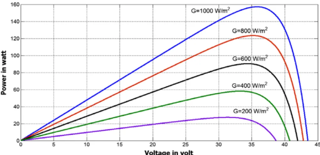
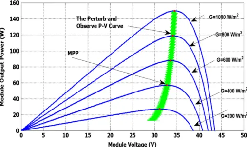
to the fact that it is a green source. The only emissions associ-ated with PV power generation are those from the production of its components. However, the development for improving the efficiency of the PV system is still a challenging field of re-search. MPPT algorithms are necessary in PV applications be-cause the MPP of a solar module varies with the irradiation and temperature as shown inFigs. 1 and 2, so the use of MPPT algorithms is required in order to obtain the maximum output power from a solar array (Masters, 2004). When a PV module is directly coupled to a load, the PV module’s operating point will be at the intersection of its I–V curve and the load line which is the I–V relationship of load.
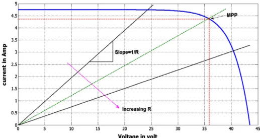
InFig. 3, a resistive load has a straight line with a slope of 1/Rloadas shown inFig. 4. In other words, the impedance of load dictates the operating condition of the PV module. In general, this operating point is seldom at the PV module’s MPP, thus it is not producing the maximum power.
To mitigate this problem, a maximum power point tracker (MPPT) can be used to maintain the PV module’s operating
* Corresponding author. Tel.: +20 114 2706477. E-mail address:[email protected](A. Ghitas).
Peer review under responsibility of National Research Institute of Astronomy and Geophysics.
Production and hosting by Elsevier
2090-9977ª2013 Production and hosting by Elsevier B.V. on behalf of National Research Institute of Astronomy and Geophysics.
point at the MPP. MPPTs can extract more than 97% of the PV power when properly optimized (Hohm and Ropp, 2002). A photovoltaic system for isolated grid-connected appli-cations as shown in Fig. 5is a typically composed of these main components:
(1) PV module that converts solar energy to electric one. (2) DC–DC converter that converts produced DC voltage
by the PV module to a load voltage demand.
(3) Digital controller that drives the converter operation with MPPT capability.
In the literature, many maximum power point tracking (MPPT) techniques are proposed and implemented. The MPPT control method, which uses one estimate processes
between every two Perturb processes in search for the maxi-mum PV output (EPP) is proposed in Liu et al. (2004). An intelligent approach for MPPT DC/DC Boost converter fo-cused on P&O algorithm and compared to a designed fuzzy lo-gic controller is presented in Farhat and Sbita (2011). A comparative study of two type of maximum power point track-ing (MPPT) which is Perturb and Observe (P&O) and incre-mental conductance method are introduced in Kumar et al. (2011). An Artificial Neural Networks is proposed in Amrouche et al. (2007)to detect the atmospheric conditions variations in order to adjust the perturbation step for the next perturbation cycle. The presented tracking algorithm shows better steady state and dynamical performance than tradi-tional P&O. The implementation of fuzzy logic controller based on the change of power and change of power with re-spect to change of voltage is studied inChin et al. (2011), fuzzy determines the size of the perturbed voltage. The performance of Fuzzy Logic with various membership functions (MFs) is tested to optimize the MPPT. Fuzzy Logic can facilitate the tracking of maximum power faster and minimize the voltage variation. A novel intelligent fuzzy logic controller for MPPT in grid-connected photovoltaic systems based on boost con-verter and single phase grid-connected incon-verter is introduced in Zeng et al. (2005). This is simple to be implemented on Fig. 1 PV module voltage–power at different irradiance levels.
Fig. 2 PV module current–voltage at different temperature levels.
Fig. 3 PV module is directly connected to a (variable) resistive load.
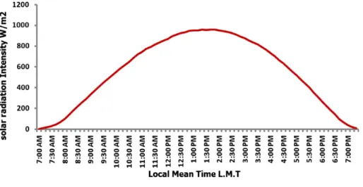
MCU chip and needs no memory space to save fuzzy rules, and that optimizing factor in the fuzzy inference equation can adjust fuzzy rules on-line automatically to improve system control effect, which provides the system with an intelligent characteristic. An intelligent control method for MPPT of a photovoltaic system under variable temperature and insolation conditions which uses a fuzzy logic controller applied to a DC– DC converter device is proposed inCheikh Aı¨t et al. (2007). Results of this simulation are compared to those obtained by the perturbation and observation controller. A fuzzy logic con-trol (FLC) is proposed inTakun et al. (2011)to control MPPT for a photovoltaic (PV) system; this technique uses the fuzzy logic control to specify the size of incremental current in the current command of MPPT. This paper presents a maximum power point tracker (MPPT) using Fuzzy Logic for a PV sys-tem. The work focused on the well known Perturb and Ob-serve (P&O) algorithm and compared to a designed fuzzy logic controller (FLC). A simulation work dealing with MPPT controller, a DC/DC C´uk converter feeding a load is achieved. The results will show the validity of the proposed Fuzzy Logic MPPT in the PV system. Most of the performed works in the literature reviews in this point is based on assumed not actual solar radiation data but this paper is used a real data for solar radiation measured by solar radiation and meteorological sta-tion located at Nasta-tional Research Institute of Astronomy and Geophysics Helwan, Cairo, Egypt which is located at latitude 29.87N and longitude 31.30E. The station is over a hill top of about 114 m height above sea level. Example of the daily re-corded measured solar radiation is shown inFig. 6.
2. Mathematical model
2.1. Modeling of PV cell and module
A PV cell can be simulated by a real diode in parallel with an ideal current sourceISCwhich depends on impinging radiation. The generalized equivalent circuit of the PV cell including both series and parallel resistances is shown inFig. 7 Hidouri (2010) and Krishna (2009).
One can derive the following equation for current and volt-age in one diode model:
ISC¼IþIdþIp ð1Þ I¼ISCI0 exp qðVþIRSÞ AkT 1 VþIRS RP ð2Þ I0¼ ISCqV eAkT1 ð3Þ
The reverse saturation current is dependent on the temper-ature and is given by the following equation:
I0ðTÞ ¼I0ðTrefÞ T Tref 3 exp qEG AK 1 Tref 1 T ð4Þ The short circuit current depends on the solar radiation and cell temperature as follows:
ISC¼½ISCrþKiðTTrefÞ G ð5Þ
whereI, cell output current;ISC, short circuit current;Io, re-verse diode saturation current;V, cell output voltage;RS, cell series resistance (X);RP, cell parallel resistance (X); A, diode ideality factor;K, Boltzmann constant (1.38e23);T, cell junc-tion temperature (C);Tref, the reference temperature of the PV cell;Io(Tref), the cell reverse saturation current at reference temperature;EG, the band gap of semi conductor used in the cell;Iscr, the cell short circuit current at reference temperature and radiation;Ki, the short circuit current temperature coeffi-cient;G, the solar radiation in kW/m2.
The PV module consists ofnsof series cells andnpof par-allel branches as shown inFig. 8.
Fig. 5 Block diagram of the stand-alone PV system.
The PV module’s currentIMunder arbitrary operating con-ditions can be described as:
IM¼NpISCNpI0 exp q VM NSþI M;RM S AkT 2 4 3 51 8 < : 9 = ; VM NSþI M;RM S RM P ! ð6Þ RM S ¼ NS NPR C S andR M P ¼ NP NSR C P ð7Þ
whereRCSandRCP are the series resistance and the parallel resis-tance of the cell respectively.
2.2. Modeling of DC/DC converter
The heart of MPPT hardware is a switch-mode DC–DC con-verter. It is widely used in DC power supplies and DC motor drives for the purpose of converting unregulated DC input into a controlled DC output at a desired voltage level (Mohan 2003). MPPT uses the same converter for a different purpose: regulating the input voltage at the PV MPP and providing load matching for the maximum power transfer. The topologies of DC–DC converters are further categorized into three types: step down (buck), step up (boost), and step up & down (buck–boost). The buck topology is used for voltage step-down. In PV applications, the buck type converter is usually used for charging batteries and in LCB for water pumping sys-tems. The boost topology is used for stepping up the voltage. The grid-tied systems use a boost type converter to step up the output voltage to the utility level before the inverter stage. Fig. 6 Example of the daily measured solar radiation intensity at Helwan.
Fig. 7 The equivalent circuit for a PV cell.
Fig. 8 The equivalent circuit for a PV module.
Fig. 9 Circuit diagram of the basic Cu´k converter.
Fig. 10 Basic Cu´k converter when the switch is ON.
(L2) is transfer to the load through the loop formed by D, C2 andRload. Thus, the following relationship is established Taufik EE410 (2004). Assuming that this is an ideal converter, the average power supplied by the source must be the same as the average power absorbed by the load.
Pin¼Pout ð8Þ VSIL1¼VoIL2 ð9Þ IL1 IL2 Vo VS ð10Þ Finally one can derive the following equation:
Vo VS
D
1D ð11Þ
where:Dis the duty cycle (0 <D< 1)
The output voltage relation to the duty cycle (D) is: If 0 <D< 0.5 the output is smaller than the input. IfD= 0.5 the output is the same as the input. If 0.5 <D< 1 the output is larger than the input.
3. Proposed technique
3.1. Perturb and observe algorithm
Over the past decades many methods to find the MPP have been developed and published. These techniques differ in many aspects such as required sensors, complexity, cost, range of
effectiveness, convergence speed, correct tracking when irradi-ation and/or temperature change, hardware needed for the implementation or popularity, among others. A complete Fig. 12 The power voltage characteristic for the PV module at
G= 1000 W/m2and temperature 25C. NO Increase D (k) Decrease D (k) Decrease D (k) Increase D (k)
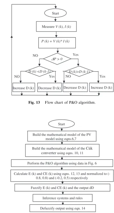
Fig. 13 Flow chart of P&O algorithm.
Start
Build the mathematical model of the PV model using eqns.6,7
Build the mathematical model of the Cúk converter using eqns. 10, 11 Perform the P&O algorithm using data in Fig. 6 Calculate E (k) and CE (k) using eqns. 12, 13 and normalized to
(-0.8, 0.8) and (-0.2, 0.5) respectively Fuzzify E (k) and CE (k) and the output dD
Inference systems and rules Defuzzify output using eqn. 14
Fig. 14 Proposed MPPT based on a fuzzy controller.
Table 1 Fuzzy logic controller rules base.
E CE NB NM NS NZ ZE PZ PS PM PB NB ZE ZE ZE PB PB PB PB PB PB NM ZE ZE ZE PM PM PM PM PM PM NS ZE ZE ZE PS PS PS PS PS PS NZ PS PM ZE ZE ZE ZE ZE NM NS ZE PS PM ZE ZE ZE ZE ZE NM NS PZ NS NM ZE ZE ZE ZE ZE PM PS PS NS NS NS NS NS NS ZE ZE ZE PM NM NM NM NM NM NM ZE ZE ZE PB NB NB NB NB NB NB ZE ZE ZE
review of 19 different MPPT algorithms can be found inEsram and Chapman (2007). The Perturb and Observe (P&O) algo-rithm is the most commonly used in practice because of its ease of implementation. This controller is introduced briefly in Ref. Santos et al. (2006).Fig. 12shows the power voltage character-istic for the PV module at solar radiation = 1000 W/m2and temperature 25C.
In the P&O algorithm, the operating voltage of the PV ar-ray is perturbed by a small increment, and the resulting change in power,DP, is measured. IfDPis positive, then the perturba-tion of the operating voltage moved the PV array’s operating point closer to the MPP. Thus, further voltage perturbations in the same direction (that is, with the same algebraic sign) should move the operating point toward the MPP. If DP is negative, the system operating point has moved away from the MPP, and the algebraic sign of the perturbation should be reversed to move back toward the MPP. Fig. 13 shows
the flowchart of this algorithm. P&O algorithm has some drawbacks which are inLiu et al. (2004); it cannot always opates at the maximum power point due to the slow trial and er-ror process, and thus the solar energy from the PV arrays are not fully, the PV system may always operates in an oscillating mode and finally; the operation of PV system may fail to track the maximum power point.
3.2. Fuzzy Logic MPPT controller
The use of fuzzy logic control has become popular over the last decade because it can deal with imprecise inputs, does not need an accurate mathematical model and can handle nonlinearity. Microcontrollers have also helped in the popularization of fuz-zy logic control (Esram and Chapman, 2007).
The Fuzzy Logic consists of three stages: fuzzification, inference system and defuzzification. Fuzzification comprises Fig. 15 The power–voltage characteristic of the P&O algorithm.
the process of transforming numerical crisp inputs into linguis-tic variables based on the degree of membership to certain sets. Membership functions are used to associate a grade to each linguistic term. The proposed MPPT sown in Fig. 14 based on Fuzzy Logic has two inputs which are the error E and change of errorCEat sampled timeskdefined by:
EðkÞ ¼PðkÞ Pðk1Þ
VðkÞ Vðk1Þ ð12Þ
Fig. 17 The output power–duty cycle characteristic.
Fig. 18 The output voltage–output current characteristic.
Fig. 19 The fuzzy member ship functions for inputE(k).
Fig. 20 The fuzzy member ship functions for inputCE(k).
Fig. 21 The fuzzy member ship functions for outputdD(k).
CEðkÞ ¼EðkÞ Eðk1Þ ð13Þ whereP(k)andV(k)are the instant power and voltage of the photovoltaic module respectively.
The controller crisp value (dD) is the output of the fuzzy con-troller. The proposed membership functions for both inputs and outputs are NB (Negative Big), NM (Negative Medium), NS (Negative Small), NZ (Negative Zero), ZE (Zero), PZ (Positive Zero), PS (Positive Small), PM (Positive Medium) and PB (Posi-tive Big). The proposed fuzzy rules which are carried out by using Madani’s method are shown inTable 1. The defuzzification uses the centre of gravity to compute the output of this FLC: D¼ Pn j¼1lðDjÞ Dj Pn j¼1l ðDjÞ ð14Þ
If E is PB and EC is ZE then crisp dD is NB, its means that if the operating point is far away from the maximum power point (MPP) by the left side, and the variation of the slope of the curve is almost Zero; then increase the duty cycle (dD). 4. Numerical analysis
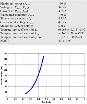
The proposed technique in this paper uses bpsx150 PV module which has electrical characteristic shown in Table. 2 (http://www.abcsolar.com).1
The bpsx150 PV module is simulated by Matlab program Version 7.10 and the power voltage characteristic at different solar radiation is shown in Fig. 1, also the current voltage characteristic at different solar radiation is shown inFig. 2. The simulated bpsx150 PV module and the real measured solar radiation shown in Fig. 6 are used with another program that coupled the bpsx150 PV module with Cu´k converter and the P&O algorithm is performed. The power–voltage and voltage–current characteristic and the voltage–current characteristic of P&O algorithm are shown inFigs. 15 and 16.
The relationship between the output powers of converter versus the duty cycle is shown inFig. 17.
The output voltage versus the output current is shown in Fig. 18. After simulating the perturb and observe algorithm with Cu´k converter the errorE(k)is calculated and normal-ized between (0.8 and 0.8),CE(k)is calculated and normal-ized between (0.26 and 0.069) also the change in duty cycle dDis normalized between (0.2 and 0.5). The fuzzy member-ship function used in this study is Gaussian surface.
The fuzzy member ship functions for inputs and output are written as follows and are shown inFigs. 19–22.
[Input1] Name = ‘Error’ Range = [0.8 0.8] NumMFs = 9 MF1 = ‘NB’:‘gaussmf’, [0.084930.8] MF2 = ‘NM’:‘gaussmf’, [0.084930.5] MF3 = ‘NS’:‘gaussmf’, [0.084930.2] MF4 = ‘NZ’:‘gaussmf’, [0.08490.0037] MF5 = ‘ZE’:‘gaussmf’, [0.08493 0] MF6 = ‘PZ’:‘gaussmf’, [0.0849 0.0034] MF7 = ‘PS’:‘gaussmf’, [0.0849 0.01] MF8 = ‘PM’:‘gaussmf’, [0.08493 0.5] MF9 = ‘PB’:‘gaussmf’, [0.08493 0.8] [Input2]
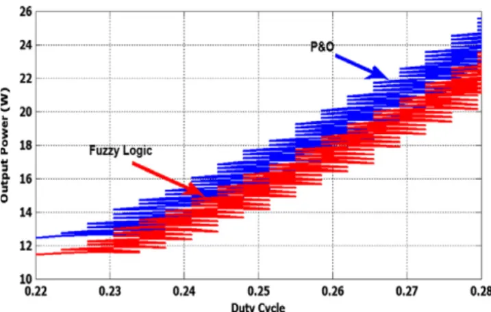
Name = ‘Error change’ Range = [0.26 0.069] NumMFs = 9 MF1 = ‘NB’:‘gaussmf’, [0.017460.260356446370531] MF2 = ‘NM’:‘gaussmf’, [0.017460.2] MF3 = ‘NS’:‘gaussmf’, [0.017460.1] MF4 = ‘NZ’:‘gaussmf’, [0.017460.009] MF5 = ‘ZE’:‘gaussmf’, [0.01746 0] MF6 = ‘PZ’:‘gaussmf’, [0.01746 0.009] MF7 = ‘PS’:‘gaussmf’, [0.01746 0.022] MF8 = ‘PM’:‘gaussmf’, [0.01746 0.05] MF9 = ‘PB’:‘gaussmf’, [0.01746 0.069] [Output1] Name = ‘DeltaD’ Range = [0.2 0.5] NumMFs = 9 MF1 = ‘NB’:‘gaussmf’, [0.037160.2] MF2 = ‘NM’:‘gaussmf’, [0.037160.15] MF3 = ‘NS’:‘gaussmf’, [0.037160.1] MF4 = ‘NZ’:‘gaussmf’, [0.037160.009] MF5 = ‘ZE’:‘gaussmf’, [0.03716 0] MF6 = ‘PZ’:‘gaussmf’, [0.03716 0.009] MF7 = ‘PS’:‘gaussmf’, [0.03716 0.1] MF8 = ‘PM’:‘gaussmf’, [0.03716 0.2] MF9 = ‘PB’:‘gaussmf’, [0.03716 0.5] Fig. 23 Power versus duty cycle for both P&O algorisms and
Fuzzy Logic.
Fig. 24 Module voltage versus duty cycle for both P&O algorisms and Fuzzy Logic.
1
Helwan, Cairo, Egypt.
The work focused on the well known Perturb and Observe (P&O) algorithm and compared to a designed fuzzy logic con-troller (FLC). A simulation work dealing with MPPT control-ler, a DC/DC C´uk converter feeding a load is achieved. The results showed the validity of the proposed fuzzy logic MPPT in the PV system.
References
Amrouche, B., Belhamel, M., Guessoum, A., 2007. Artificial intelli-gence based P&O MPPT method for photovoltaic systems. Review of Renewable Energy ICRESD-07 Tlemcen, 11–16.
Cheikh Aı¨t, M.S., Larbes, C., Tchoketch, G.F., Zerguerras, A., 2007. Maximum power point tracking using a fuzzy logic control scheme. Revue des Energies Renouvelables 10 (3), 387–395.
Chin, C.S., Neelakantan, P., Yoong, H.P., Teo, K.T.K., 2011. Optimisation of fuzzy based maximum power point tracking in PV system for rapidly changing solar irradiance. Transaction on Solar Energy and Planning ISSN: 2229–8711 2.
Esram, T., Chapman, P.L., 2007. Comparison of photovoltaic array maximum power point tracking techniques. IEEE Transactions on Energy Conversion 22 (2), 439–449.
Engineering & Applied Sciences 1 (4).
Liu, C., Wu, B., Cheung, R., 2004. Advanced algorithm for MPPT control of photovoltaic systems. Canadian Solar Buildings Con-ference Montreal.
Masters, Gilbert.M., 2004. Renewable and Efficient Electric Power Systems. John Wiley & Sons Inc., Hoboken, New Jersey. Mohan, Undeland, Robbins, 2003. Power Electronics Converters,
Applications and Design, third ed. John Wiley & Sons Ltd.. Santos, L.J.L., Antunes, F., Chehab, A., Cruz, C., 2006. A maximum
power point tracker for PV systems using a high performance boost converter. Solar Energy 80 (7), 772–778.
Takun, P., Kaitwanidvilai, S., Chaiyan Jettanasen., 2011. Maximum power point tracking using fuzzy logic control for photovoltaic systems. Proceedings of the International MultiConference of Engineers and Computer Scientists 2011, II, IMECS 2011, Hong Kong.
Taufik EE410, 2004. Power Electronics I. Lecture Note Cal Poly State University, San Luis Obispo.
Zeng, G., Zhang, X., Ying, J., Changan Ji., 2005. A novel intelligent fuzzy controller for MPPT in grid-connected photovoltaic systems. Proceedings of the Fifth WSEAS/IASME International Conference on Electric Power Systems, High Voltages, Electric Machines, Tenerife, Spain, pp. 515–519.