e-ISSN: 2278-067X, p-ISSN: 2278-800X, www.ijerd.com
Volume 11, Issue 11 (November 2015), PP.76-93
Implementation of FLC in Power Control for Hybrid AC/DC
Micro grid
B. SRAVANKUMAR
1, A. PURNA CHANDRA RAO
21
PG Scholar, Department of Electrical & Electronics Engineering, P.V.P. Siddhartha Institute of Technology Vijayawada-520007, A.P, India
2Department of Electrical & Electronics Engineering,
P.V.P. Siddhartha Institute of Technology Vijayawada-520007, A.P, India
Abstract: -In this paper hybrid AC/DC micro grid comprises of DC and AC sub grids interconnected by power electronic interfaces. But existing micro grids are purely AC or DC grids. The major purpose is to manage the power flow among all sources distributed throughout the different types of sub grids. The hybrid grid reduces the process of multiple DC-AC-DC or AC-DC-DC conversions in an individual grid where the number of converter stations for converting AC to DC or DC to AC power are reduced. These power generating stations interconnected to form a micro grid system needed number of multiple reverse conversations (AC-DC or DC-AC) for consumer applications this results increase circuit complexity, cost and system have less reliability. The proposed grid can operate in both standalone and grid connected mode. Fuzzy controller is used for smooth power transfer.
Keywords: -Hybrid micro grid, Proportional integral controller, Standalone,Grid connected mode.
I. INTRODUCTION
The increasing number of renewable energy sources and distributed generation (DG) requires new technique for the operation and management of the electricity grid to enhance proper power sharing. In the present power scenarios, when distributed generations are mentioned for small scale generations to meet the various customer demand. The coordination of these small scale generations may consist of photovoltaic, batteries, wind and fuel cells which are formed as Micro-grid [1]. Interest on micro grid is rapidly increasing as it is based on the renewable energy sources, which connects to utility grid and various types of loads. In the grid tied mode, it is connected with utility whereas in case of autonomous mode it is totally disconnected. In case of autonomous mode it becomes totally independent and fulfills the demands of customers from the renewable energy sources [2],[3]. Grid connected, Islanding mode, Transition mode. Therefore a suitable control strategy is required to coordinate the operation of DC sources AC sources and IC, which need a fast communication link reliability concern, which uses a decentralized control among which droop control method can be used for which proper power sharing between AC and DC micro grid.
During islanding operation the IC act as a role of supplier to one micro grid at the same time act as load to other micro grid and shares the power demand between existing sources. Another challenge is that since the generated power in each micro grid is limited the power management system should be able to share the power demand between the existing ac and dc sources [4]. Therefore a specified droop control method is needed to coordinate the power flows and to cover acceptable power sharing. A two stage modified droop method is used for the bidirectional power control of the IC during different operation modes of the hybrid AC/DC micro grid. By measuring the AC micro grid frequency and the DC micro grid voltage and using proposed droop characteristic [5, 6]. The power management strategy provides the power reference for the IC control to share the power demand between the existing power sources in both ac and dc micro grid.
though in subordinate. Consequently, linking AC micro-grids with DC micro-grids and employing the profits of the both micro-grids, has become interesting in recent studies [11].This paper is arranged as follows: in Section II, explain the system structure and operationmodesof hybrid AC/DC micro grid. In Section III, Droop control strategy for individual AC micro grids and DC micro grids is explained. In section IV, proposed IC control during islanding are discussed. In section V, fuzzy logic controller is explained. In section VI, Power Control and Management in a Hybrid AC/DC Micro grid is analyzed, and the corresponding results are also presented with fuzzy logic controller. Finally, conclusion is given in Section VII.
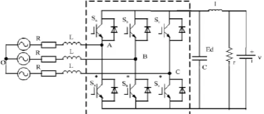
II. SYSTEM STRUCTURE AND OPERATION MODES
A simple hybrid AC/DC micro grid is shown in Fig. 1. It consists of an ac micro grid with conventional DG sources, a DC micro grid with two DC type sources and an IC links the two micro grids together. Each of these micro grids also includes their individual loads. Besides, during normal grid operation the hybrid micro grid is connected to the main utility grid through the AC micro grid. Basically, the micro grids are thought to operate in grid-connected or islanding modes in the grid-connected operation mode of the hybrid micro grid, the AC micro grid dynamics are governed directly by the main utility grid and the IC primarily regulates the DC micro grid voltage and controls the power balance, as well. In this operating condition the DC sources can generate a constant power or can operate in maximum power point for the renewable energy sources. In the islanding mode of operation, and during light loading of the DC part, the demanded power is shared among the
DC sources using the (P− 𝑉𝑑𝑐) droop characteristics. When over-loading happens in the DC micro grid, the
interlinking converter will also participate in load sharing using the proposed AC-DC droop control. In the following, the performance of the hybrid AC/DC micro grid is described in either of these two modes.
Fig.1. A typical hybrid AC/DC micro grid.
A. Grid-Connected Mode
While the hybrid AC/DC micro grid is connected to the main utility grid, dg sources in the AC micro grid are expected to either generate a specified real/reactive power, or act as terminal voltage regulator with a specified amount of active power and variable reactive power [5]. On the other hand, the utility grid operates as slack bus to support the difference in the active/reactive power demand and to sustain the micro grid frequency. Similarly, in DC micro grid, DG sources would be controlled to generate a specified active power. However, the utility grid is still responsible for voltage support and power balance through the IC. According to Fig. 1 and neglecting the power losses, this mode can be described,
In this mode the renewable energy sources in the micro grid can operate in maximum power point, energy storages can charge and non-renewable sources can be managed, e.g., for peak shaving purposes, loss reduction or economical goals. In the ac micro grid, DGs could also generate a specified reactive power, regulate terminal voltage or may be used for power quality aims [21]. These power management studies have been studied in DC micro grids [7], [8] and it is not intended to be followed in this paper.
B. Islanding Mode
Whenthehybridgridoperatesintheislandingmode, an interlinking converter acts as a converter and inverter mode to supply the power from AC micro grid to DC micro grid and DC micro grid to AC micro grid for balanced the power in both grids. In this mode Utility grid is not supplying power, Static switch is open, Feeder A, B, C is being supplied by Micro sources, Feeder D (not sensitive) is dead. In the islanding mode, the total load demand should be shared and managed autonomously by the existing DGs in the both micro grids, which involves rapid and flexible active/reactive power control strategies to minimize the micro grid dynamics. Different operating states may occur during islanding operation of the hybrid micro grid. For the sake of appropriate performance of the hybrid AC/DC micro grid under different grid conditions, four main operating states are considered in the islanding mode, as follows:
Islanding state I: This operation state corresponds to the islanding operation of hybrid AC/DC micro grid during which power generation in AC micro grid and DC micro grid suffices their individual loads (light load condition). The generation units in each micro grid will regulate its power to meet the load. In this state, the IC halts transferring power and can just supply reactive power for the AC micro grid. This state is expressed by,
𝑃𝑖𝑐∗ = 𝑃𝑔𝑟𝑖𝑑∗ = 0 (3)
DC micro-grid: 𝑝𝑑𝑐 ,𝑖𝑙𝑜𝑎𝑑
𝑖 ≤ 𝑃𝑑𝑐 ,𝑖 (4)
AC micro-grid: 𝑃𝑎𝑐 ,𝑖 𝑙𝑜𝑎𝑑 ≤ 𝑃
𝑎𝑐 ,𝑖 𝑖
𝑖 (5)
Islanding state II: This state represents the case where the generated power in AC micro grid is deficient for the AC load demand but there is surplus power in the DC micro grid. Therefore, the required power should be supplied by the dc sources through the IC. In this state we have,
DC micro-grid: 𝑃𝑑𝑐 ,𝑖𝑙𝑜𝑎𝑑
𝑖 < 𝑃𝑖 𝑑𝑐 ,𝑖 (6)
AC micro-grid: 𝑃𝑎𝑐 ,𝑖𝑙𝑜𝑎𝑑 > 𝑃
𝑎𝑐 ,𝑖 𝑖
𝑖 (7)
𝑃𝑔𝑟𝑖𝑑∗ = 0, 𝑃𝑖𝑐∗ = 𝑃𝑖 𝑎𝑐 ,𝑖− 𝑃𝑖 𝑎𝑐 ,𝑖𝑙𝑜𝑎𝑑 − 𝑃𝑎𝑐𝑙𝑜𝑠𝑠 (8)
Islanding state III: This state is similar to state II, except that the power deficit occurs in the DC micro grid and the AC micro grid is in light load condition. Therefore, the AC micro grid supplies the required power for DC micro grid. In this case,
DC micro-grid : 𝑃𝑑𝑐 ,𝑖𝑙𝑜𝑎𝑑 > 𝑃
𝑑𝑐 ,𝑖 𝑖
𝑖 (9)
AC micro-grid : 𝑃𝑎𝑐 ,𝑖𝑙𝑜𝑎𝑑
𝑖 < 𝑃𝑖 𝑎𝑐 ,𝑖 (10)
𝑃𝑔𝑟𝑖𝑑∗ = 0 , 𝑃𝑖𝑐∗ = 𝑃𝑖 𝑑𝑐 ,𝑖− 𝑃𝑖 𝑑𝑐 ,𝑖𝑙𝑜𝑎𝑑 − 𝑃𝑑𝑐𝑙𝑜𝑠𝑠 (11)
Islanding state IV: This operation state relates to the case during which the load demand in both AC micro grid and DC micro grid are greater than the maximum available sources capacity (overload condition). In this state, the IC halts transferring power and a proper load shedding strategy must be run to stabilize the grids. This state is described by,
𝑃𝑖𝑐∗ = 𝑃𝑔𝑟𝑖 𝑑∗ = 0 (12)
DC micro-grid: 𝑝𝑖 𝑑𝑐 ,𝑖𝑙𝑜𝑎𝑑 ≥ 𝑃𝑑𝑐 ,𝑖 (13)
AC micro-grid: 𝑃𝑎𝑐 ,𝑖 𝑙𝑜𝑎𝑑
𝑖 ≥ 𝑃𝑖 𝑎𝑐 ,𝑖 (14)
III. DROOP CONTROL STRATEGY FOR INDIVIDUALMICRO GRIDS
(i)Control of DGS in the AC Micro grid
when the system frequency decreases. Similarly, for reactive power management voltage-droop (V-Q) is exploited. Reactive power generation of a DG is determined based on deviations in the bus voltage. Therefore, the DG source acts in response to the measured local voltage deviations caused by either the system or the local load‘s-P and V-Q characteristics could be described mathematically by,
𝑃𝑟𝑒𝑓 = − 1 𝐾𝑎𝑐 𝑤
0 ─ 𝑤 + 𝑃0 (15)
𝑄𝑟𝑒𝑓 = − 1 𝐾𝑞 𝑚𝑎𝑥 𝑉
0 ─ 𝑉 + 𝑄0 (16)
By this power control method, during the grid-connected mode where the frequency of the system in fixed, real
power generation of the DG is controlled by 𝑃0.
Fig.2. Configuration of the IC interfacing AC and DC micro grids.
Fig. 3.Proposed AC-DC droop characteristic.
(ii) Control of DGs in DC Micro grid
Alternatively, for the DC micro grid the dc voltage-droop (𝑉𝑑𝑐−P) control method is used for power
sharing between DG sources in the micro grid. Typical (𝑉𝑑𝑐−P) droop characteristics can be expressed by
𝑃𝑟𝑒𝑓 = − 1 𝑘𝑑𝑐 𝑉𝑑𝑐
0 ─ 𝑉
𝑑𝑐 + 𝑃𝑑𝑐0 (17)
IV. PROPOSED IC CONTROL FOR ISLANDING OPERATION
As discussed in the previous sections, during the islanding operation of the hybrid AC/DC micro grid different operating states might arise and the IC should recognize these states and manage the whole hybrid micro grid. The following decentralized control strategy is adopted for this purpose. The power management should determine the amount of active power that the IC must transfer from one micro grid to the other. In order to provide the power reference command, the DC bus voltage of the IC and the frequency of the AC micro grid are
AC-DC Droop Eq.(10)
V
dc - P Droop Eq.(19)ω P Droop Eq.(15) AC-DC Droop Eq.(10) Over load blocking logic (Fig.6) ω
Power transfer from dc to ac
Power Transer from
ac to dc
Fig.4. Proposed real power controller for the IC.
Utilized as input to the power management system. Considering the electrical energy stored in the DC capacitor is,
𝑊𝑑𝑐 = 𝐶𝑑𝑐𝑉𝑑𝑐2 (18)
Neglecting the switching losses in the converter 𝑃𝑑𝑐 ≈ 𝑃𝑎𝑐, the dynamics in the DC capacitor energy is the
difference of power transfer between AC and DC micro grids. Therefore,
𝑑
𝑑𝑡𝑊𝑑𝑐 = 1 2𝑐𝑑𝑐
𝑑 𝑑𝑡 𝑉𝑑𝑐
2 = 𝑃
𝑑𝑐− 𝑃𝑎𝑐 =△ P (19)
On the other side, considering the w-P characteristic in the AC micro grid, The ―AC-DC droop‖
characteristic is shown in Fig.3.δw and 𝛿𝑣 are the dead zone bands for the allowable variation of angular
frequency and DC voltage, respectively. Dead zone is utilized in the proposed ―AC-DC droop‖ in order to prevent any power transfer during light load operation of individual micro grids. During such operation condition the generating units in each micro grid will regulate the generated power to supply the corresponding
micro grid load using the relevant Vdc– P or w–P droop characteristics. v2shed and w shed are respectively the
minimum DC voltage and AC micro grid frequency drop in dc and ac micro grids that the system is supposed to undergo load shedding. Furthermore, since the IC is not the mere frequency or DC voltage controller in the hybrid AC/DC micro grid, it is necessary to participate in power sharing between AC and DC sources. To
implement this scheme, the output of the AC/DC droop is fed to the Vdc– P or w– P and droops of the IC. It is
necessary to mention that since positive sign for power transfer in the IC is considered to be from DC to AC, the
power for Vdc– P droop should be regarded with negative sign. Finally, according to V ref dc and w ref the amount
of power to be transferred via the IC is determined by the two reference power calculated through these two loops. A schematic block diagram of the proposed power management strategy for the IC is depicted in Fig.4. The impact of the proposed droop control for the IC on the power sharing of sources in each micro grid is illustrated within two load increase scenarios in each microgrid,
1) In the first scenario it is assumed that the DC micro grid is near overloading and there is excess power in the
AC micro grid. Upon increasing the load in the dc micro grid, the DC voltage will accordingly decrease. If the
voltage drop is beyond 𝛿𝑉, referring to the proposed AC-DC droop (Fig. 3) this voltage deviation produces a
new reference angular frequency wref .This wref will then determines the reference power for the IC power
micro grid. On the other hand, the IC takes the roll of a load for the AC micro grid and increases the power generation of the aAC sources.
2) The other scenario happens when the AC micro grid is near overloading. When the ac load increases again,
causes the frequency to decrease below 𝛿𝑊. Referring to the proposed AC-DC droop a new reference voltage
V dc ref is presented. Finally, by using the Vdc– P droop the required power to be transferred to the dc micro grid
is determined. Therefore, according to these two scenarios whenever the load increases in one of the micro grids, the ―AC-DC droop‖ characteristic relates the AC and DC micro grids using the dc link performance and the equivalent frequency droop characteristic of the AC micro grid which is determined by,
△ 𝑃 = 𝑘𝑤 ∆𝑤 , 𝑘𝑤 = 1
𝑅1+ 1
𝑅2+ ⋯ + 1
𝑅𝑛 + 𝐷 (20)
Where R,……,Rn are droop coefficient of ac sources and D is the load-damping constant of the ac micro
grid. Using this droop characteristic it is possible to relate the different droops of AC and DC micro grid and consequently share the power in the whole micro grid. By this power management strategy the response of IC in different islanding states is as follows:
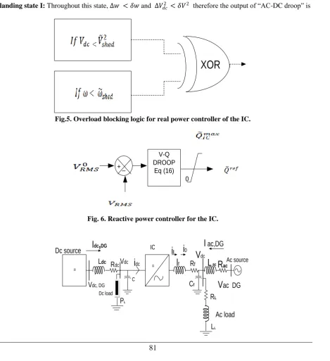
Islanding state I: Throughout this state, ∆𝑤 < 𝛿𝑤 and ∆𝑉𝑑𝑐2 < 𝛿𝑉2 therefore the output of ―AC-DC droop‖ is
XOR
Fig.5. Overload blocking logic for real power controller of the IC.
V-Q DROOP
Eq (16) + _
0
Fig. 6. Reactive power controller for the IC.
= = Ac source
Ac load
Dc loadDc source
C ICC
fR
LL
LP
LL
dcI
dc,
DGi
0i
lI
ac,DG
L
acR
acR
dcV
ac DG
V
dc, DGFig. 7. Simplified equivalent model of the hybrid micro-grid.
𝑉𝑑𝑐𝑟𝑒𝑓= 𝑉𝑑𝑐0 for DC micro grid and 𝑤𝑟𝑒𝑓 = 𝑤0 for AC microgrid. Consequently, 𝑃𝑟𝑒𝑓 = 0 and IC transfers no
power.
Islanding state II: In this state ∆𝑉𝑑𝑐2 < 𝛿𝑉2 but ∆𝑤 > 𝛿𝑤 therefore,𝑃𝑟𝑒𝑓 = - 𝑃𝑑𝑐 𝑟𝑒𝑓
and IC supplies power to the AC micro grid.
Islanding state III: In this state ∆𝑤 < 𝛿𝑤 but ∆𝑉𝑑𝑐2 > 𝛿𝑉2 therefore,𝑃𝑟𝑒𝑓 = 𝑃𝑎𝑐 𝑟𝑒𝑓
and IC supplies power to the Dc micro grid.
Islanding state IV: During this state, 𝑤 < 𝑤𝑠𝑒𝑑 and 𝑉𝑑𝑐2 < 𝑉𝑠𝑒𝑑2 In order to block the IC for any power transfer, an overload blocking logic is added at the output the proposed droop control in which by using an ―EXCLUSIVE OR (XOR)‖ logic, whenever both micro grids enter overloading the IC is blocked and no power will transfer. The reactive power control of the IC is more straightforward since there is no reactive power in DC microgrid and the IC is designated to play as a voltage support in droop-control mode to share the reactive power with other DGs in ac microgrid. The reactive power sharing is based on the conventional droop the local RMS voltage is measured and using the V– Q droop, the reactive power reference is determined. Since the active power transfer is the prime task of the IC, a dynamic reactive power limit is added to the control block to consider the capacity limit of the IC. The hybrid micro-grid shown in Fig. 1 is simplified from the perspective of IC, as shown in Fig. 7. Finally, a current control scheme is utilized in IC control for tracking the reference active/reactive power calculated by the power management system.
V. FUZZY LOGIC CONTROL
L. A. Zadeh presented the first paper on fuzzy set theory in 1965. Since then, a new language was developed to describe the fuzzy properties of reality, which are very difficult and sometime even impossible to be described using conventional methods. Fuzzy set theory has been widely used in the control area with some application to power system. A simple fuzzy logic control is built up by a group of rules based on the human knowledge of system behavior. Furthermore, design of fuzzy logic controller can provide desirable both small signal and large signal dynamic performance at same time, which is not possible with linear control technique. Thus, fuzzy logic controller has been potential ability to improve the robustness of compensator. The basic scheme of a fuzzy logic controller is shown in Fig .7. and consists of four principal components such as: a fuzzy fiction interface, which converts input data into suitable linguistic values; a knowledge base, which consists of a data base with the necessary linguistic definitions and the control rule set; a decision-making logic which, simulating a human decision process, infer the fuzzy control action from the knowledge of the control rules and linguistic variable definitions; a de-fuzzy fiction interface which yields non fuzzy control action from an inferred fuzzy control action.
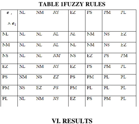
Rule Base: the elements of this rule base table are determined based on the theory that in the transient state, large errors need coarse control, which requires coarse in-put/output variables; in the steady state, small errors need fine control, which requires fine input/output variables. Based on this the elements of the rule table
FUZZYFICATION DECISION MAKING DEFUUZZYFICATION
D(k)=d(k-i)+di(k)
De(k)=e(k)-e(k-i)
KNOWLEDGE
Rule Base Data Base FLC
Error Amplifier
Crisp Value Real
Input e(k)
Real Di(k)
Vdc_actual Vdc_ref
Fuzzy µ(k)
Fuzzy µ(e)
Fig.8. Block diagram of the Fuzzy Logic Controller (FLC) for Proposed Converter.
NL NM NP EZ PP PM PL
0.8 1
0.4
0.2
0
µe,∆e
1 0.8 0.6 0.4 0.2 0
-0.2 -0.4 -0.6 -.08
e,∆e
Fig.9. Membership functions for Input, Change in input, Output.
TABLE 1FUZZY RULES
VI. RESULTS
micro grids together and connected to the main utility grid. In this paper, grid connected mode was simulated by MATLAB and shows the DC bus voltage (V), AC RMS Voltage (V), frequency (HZ), total harmonic distortion (THD), when AC/DC loads are connected to the main utility grid, islanding mode when AC and DC load is varying, when both loads are in light load and over load condition and FLC in hybrid AC/DC micro grid.
Case1: When AC/DC micro grid is connected to the main utility grid
Fig.10. Simulink diagram of hybrid AC/DC micro grid when connected to main utility grid.
Fig.10. Shows the simulink diagram of hybrid AC/DC micro grid when connected to main utility grid. In this DC load demand is high (400 KW), but two DC sources are not meeting the required load demand at time t = 1 sec DC load is suddenly drop to 200 KW as shown in fig.11.(a). and DC voltage has some disturbance is shown in fig.11.(b). To over come these problems Interlinking converter (IC) moves to inverting mode and tranfer sufficient power from AC side to DC side. At time t = 2 sec load is increased and approximately matches the generated DC power is shown in fig.11.(a).
Fig.11. Simulation waveform of (a) Active power atDCside and interlinking converter (b) DC Voltage (V).
Fig.12. Simulink diagram of islanding mode with AC variable load.
Fig.13. Simulation waveform of (a) Active power at AC side (b) IC, Active power at DC side (c) Reactive power at AC side, IC (d)DC Voltage (V) (e) AC RMSVoltage (V) (f) Frequency (Hz).
Case 3: Islanding mode when DC load is varying
Fig.15. Simulation wave form of (a) Grid, Active poweron AC side (b) Active power on DC side, IC (c) Grid, Reactive power on AC side, IC (d) DC Voltage (V) (e) AC RMS Voltage (V)
(f) Frequency(Hz).
Case 4: When both loads are in light load condition
Fig.16. Simulink diagram when both AC load and DC loads are in light load condition.
Fig.17. Simulation waveform of (a) Active power at AC side (b) Active power at DC side and IC (c) Reactive power at AC side, IC (d) DC Voltage (V) (e) AC RMS Voltage (V) (f) Frequency (HZ).
Fig.18.Simulink diagram of both AC load and DC loads are in over load condition.
Fig.19. Simulation waveforms of (a) Active power at AC side (b) Active power at DC load, IC (c) Reactive power at AC side, IC (d)DC Voltage (V) (e) AC RMS Voltage (V) (f) Frequency (HZ).
Case 6: FLC in hybrid AC/DC micro grid
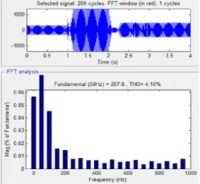
Fig.20. Shows the simulink diagram of FLC in hybrid AC/DC micro grid. The above cases have controlled by using PI controller and power electronic conversion has occurred through the interlinking converter (IC) from AC micro grid to DC micro grid. Due to this conversion,in this case, total harmonic distortion (THD) occurred in grid current up to 4.10% is shown in fig. (21). so, these harmonics are reduced to 0.04%, by using the fuzzy logic controller (FLC) is shown in fig. (22). and table 2 shows thecomparison of THD in micro grid current with PI controller and FL controller.
Fig.21.THD in grid current with PI controller.
Fig.22. THD in grid current with fuzzy logic controller.
TABLE 2THD in grid current PI
CONTROLLER
FUZZY LOGIC CONTROLLER THD 4.10% 0.04%
VII. CONCLUSION
conversion total harmonic distortion (THD) has occurred in grid current up to 4.10%. In the presence of fuzzy logic controller (FLC) these harmonics are reduced to 0.04%.
REFERENCES
[1]. N. Eghtedarpour and E. Farjah, Distributed charge/discharge control of energy storages in a renewable
energy-based DC micro grid, IET Renew. Power Gen., vol. 8, no. 1, pp. 45–57, Jan. 2014.
[2]. A. Karabiber, C. Keles, A. Kaygusuz, and B. B. Alagoz, ―An approach for the integration of
renewable distributed generation in hybrid DC/AC micro grids,‖ J. Renewable Energy, vol. 52, pp. 251–259, Apr. 2013.
[3]. P.C. Loh,D. Li, Y. K. Chai, and F. Blaabjerg, ―Hybrid AC-DC micro grids with energy storages and
progressive energy flow tuning,‖ IEEETran. Power Electron., vol. 28, no. 4, pp. 1533–1543, Apr. 2013.
[4]. P. C. Loh, D. Li, Y. K. Chai, and F. Blaabjerg, ―Autonomous control of interlinking converter with
energy storage in hybrid AC-DC micro grid,‖ IEEE Trans. Ind. Appl., vol. 49, no. 3, pp. 1374– 1382,May/Jun. 2013.
[5]. P.C.Loh,D. Li, Y. K. Chai, and F.Blaabjerg, ―Autonomous operation of hybrid micro grid with AC
and DC subgrids,‖ IEEE Trans. PowerElectron, vol. 28, no. 5, pp. 2214–2223, May 2013.
[6]. N.Eghtedarpour and E. Farjah, ―Control strategy for distributed integration of photovoltaic and energy
storage systems in dc micro grids‖, J. Renewable Energy, vol. 45, pp. 96–110, Sep. 2012.
[7]. L. Xu and D. Chen, ―Control and operation of a DC micro grid with variable generation and energy
storage, IEEE Trans‖. Power Del., vol. 26, no. 4, pp. 2513–2522, Oct. 2011.
[8]. X. Liu, P.Wang, and P. C. Loh, ―A hybrid AC/DC micro grid and its coordination control,‖ IEEE
Trans. Smart Grid, vol. 2, no. 2, pp. 278–286 , 2011.
[9]. M. N. Ambia, A. Al-Durra, and S. M. Muyeen, ―Centralized power control strategy for AC-DC hybrid
micro grid system using multi-converter scheme,‖ in Proc. IECON 2011—37th Annu. Conf. IEEE Ind.Electron. Soc., Nov. 2011, pp. 843–848.
[10]. J. M. Guerrero, J. C. Vasquez, J. Matas, L. G. Vicuna, and M. Castilla, ―Hierarchical control of droop
controlled AC and DC micro grids a general approach toward standardization,‖ IEEE Trans. Ind. Electron., vol. 58, no. 1, pp. 158–166, Jan. 2011.
[11]. D. Bo,Y. Li, Z. Zheng, and L. Xu, ―Control strategies of micro grid with hybrid DC and AC buses,‖
in Proc. 14th Eur. Conf. Power Electron.Appl. (EPE 2011), pp. 1–8.
[12]. I.-Y. Chung, W. Liu, D. A. Cartes, E. G. Collins, Jr, and S. Moon, ―Control methods of inverter
interfaced distributed generators in a micro grid system‖, IEEE Trans. Ind. App., vol. 46, no. 3, pp. 1078–1088, May/Jun. 2010.
[13]. K. Kurohane, T. Senjyu, A. Yona, N. Urasaki, and T. Funabashi, ―A hybrid smart AC/DC power
system,‖ IEEE Trans. Smart Grid‖, vol. 1,no. 2, pp. 199–204, Sep. 2010.
[14]. C. Jin, P. C. Lohl, P. Wangl, Y. Mill, and F. Blaabjerg, ―Autonomous operation of hybrid AC-DC
micro grids,‖ in Proc. IEEE ICSET, Kandy, Sri Lanka, Dec. 6–9, 2010.
[15]. H. Nikkhajoei and R. H. Lasseter, Distributed generation interface to the certs micro grid, IEEE Trans.
Power Del., vol. 24, no. 3, pp. 1598–1608, Jul. 2009.
[16]. F. Katiraei, M. R. Iravani, A. L. Dimes, and N. D. Hatziargyriou, ―Micro grids management: control
and operation aspects of micro grids‖, IEEE Power Energy Mag., vol. 6, no. 3, pp. 54–65, May/Jun. 2008.
[17]. C. K. Sao and P. W. Lehn, ―Control and power management of converter fed micro grids, IEEE
Trans. Power System‖, vol. 23, no. 3, pp. 1088–1098, Aug. 2008.
[18]. F. Katiraei and M. R. Iravani, ―Power management strategies for a micro grid with multiple distributed
generation units‖, IEEE Trans. Power Syst., vol. 21, no. 4, pp. 1821–1831, Nov. 2006.
[19]. R.H. Lasseter and P. Paigi, ―Micro grid: A conceptual solution‖, in Proc. IEEE-PESC‘04, 2004, pp.
4285–4290.
[20]. M. E. Baran and N. R. Mahajan, ―DC distribution for industrial systems opportunities and