Real Time Object Visual Inspection Based On
Template Matching Using FPGA
SANDHYA P
Asst Professor in MTIET Palamaner, India
OMKAR NAIDU V
Asst Professor in MTIET Palamaner, India
Abstract— In similarity measure, normalized cross-correlation
has found application in broad range of in image processing. This work proposes a novel technique aimed at improving the performance of exhaustive template matching based on NCC. An effective sufficient condition, capable of rapidly pruning those cross correlation score with respect to the current best candidate, can be obtained exploiting an upper bound of the NCC function. In this work Real-Time FPGA accelerates time consuming NCC template matching was presented. With this type of template matching we can inspect any industrially manufactured product on its production line with high accuracy, with increased speed of matching where huge amount of production is concerned. We got Good results by reducing search window size by reducing complexity in matching template.
Keywords— FPGA, Normalized cross-correlation, Search window, Template
I. INTRODUCTION
In similarity measure, due to its invariance to linear brightness and contrast variations, NCC has found application in a broad range of image processing such as target recognition, satellite image monitoring, stereo vision, medical diagnosis, pattern recognition and template matching. But compared to other methods NCC is relatively simple and has good accuracy. The complexity in template matching increases with real-time applications for fast image process.
Matching a template sub-image into a given image is a ubiquitous task occurring in countless analysis applications. The basic template matching algorithm consists in sliding the template over the search area and, at each position, calculating a distortion or correlation, measures estimating the degree of dissimilarity or similarity between the template and source image. Then, the maximum correlation, position is taken to represent the instance of template into the image under examination.
Since with large size images or templates the matching process can be expensive, numerous techniques aimed at speeding up the basic approach have been devised. Among the general techniques, the major one are a) the use of multi-resolution schemes, b) sub-sampling the image and the template, c) two-stage matching. Since these techniques do compare the full resolution image with full resolution template at every search position and can be trapped by local extremes resulting in wrong localization of the template under inspection. In some cases like SEA( Successive Elimination Algorithm) and PDE( Partial Distortion Elimination) allow for notably speeding up the computer up the computation required by an exhaustive-search template matching process. SEA skips the position without calculating the actual position. The main advantage of the normalized cross correlation over cross correlation is that it is less sensitive to linear changes in the amplitude of illusion in the two compared images. The NCC does not have a simple frequency domain expression. Its computation time dramatically increases as the window size increases. Here we discussed with problems and solutions for fast image processing as applicable to industrial production.
II. PROPOSEDMETHOD
The proposed method of template matching with modified NCC algorithm and method of processing as follows
A. Process overflow
B. NCC design Normalized cross-correlation is process of sliding one image over the other for matching in target image. is the search window size increases the computation complexity
increases. In order to overcome from this complexity and to increase the speed of execution we redesigned the formula as follows
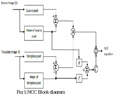
NCC=
( S − S ‘) ( – ’ ) /S ‘²+ t’ ²Here the S represents the source image, S is mean of source image, t is template and t̅ is the mean of template image. By designing this algorithm on Xilinx we have good results with less time consumption. This can be show in Fig.1 below
Fig 1:NCC Block diagram
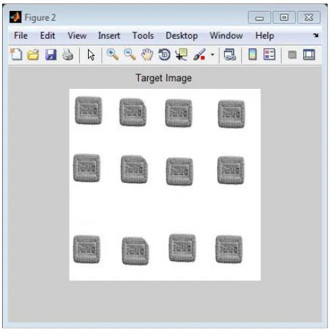
In template matching we should consider the external parameters like brightness, noise and object position in image when we are capturing image from any industry for product inspection. In order to come over from this difference we are calculating the mean of each pixel for best cross-correlation. During template matching , the template slides pixel-by-pixel in the search window to determine the most similar image block in the target image. The ideal process of template matching is shown graphically in Fig.2 below
Fig 2: Template matching
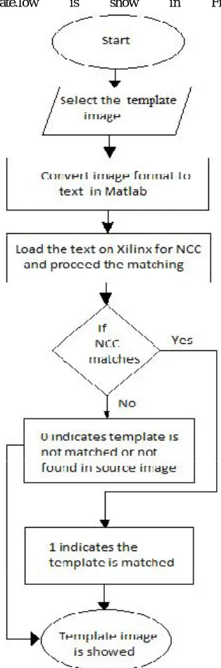
template.low is show in Fig.3 below
Fig 3: Flow graph of template matching
A typical parameter of template matching algorithm is a threshold on minimum correlation value yielding a valid match. This value allows for
discriminating when an
instance of the template is present or not in the image under examination. As we discussed earlier that when the search window size increases the complexity increases.
In our design we examined on 64x64 search window size for
The basic requirements for our paper are tabulated below TABLE I. NCC SPECIFICATIONS
Template Image size
64 x 64
Target Image size
256 x 256
Search window size
64X64
Computing time
< 5ms
System bus width
8-bit
Targeted platform
Xilinx 12.2
We have worked on various images for best template matching and to display the final results on Matlab which shows the detected object which matching the original image. In comparison with other algorithm NCC can match the image irrespective of position of object within search window.
III. EXPERIMENTALRESULTS
In this experiment, the image data width are input to the system which same for both the template and target image. The color image is converted into gray scale on matlab and then converted into text( 0’s & 1’s). Xilinx software is used for coding NCC algorithm.The device utilization of FPGA is listed in Table II. below
TABLE II. DEVICE UTILIZATION SUMMARY
Logic
Utilization
Used
Available
UtilizationNo. of Slices
94 3584 2%
No.of 4 input LTUs
166 7168 2%
No.of bounded IOBs
26 141 18%
No.of GCLKs
1 8 12%
The number of slices used on FPGA is very less and the percentage of utilization is also reduced. The other parameters can also be seen in the Table II. The time required to image processing will be less than for any kind of images.
Step 1. First selecting the template image using matlab which is shown in Fig.4 below
Fig 4: Selected template image
Step 2. Now select the target image in which matching the similar objects in image. Fig. 5 have all good objects but Fig.6 have some defected object during manufacturing. These images are experimented one after the other.
Fig 5: Target image with good products
Fig 6: Target image with defected products
The text image is loaded on Xilinx 12.2 software where it is Reading both the template and target image. This is shown on Modelsim simulator as shown in Fig. 7 and Fig.8 for both target images respectively.
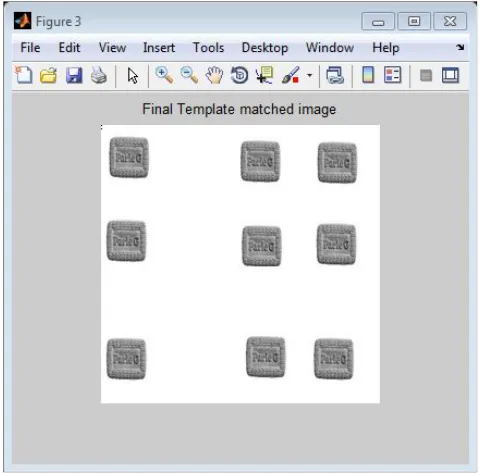
Fig 8: Final template matched image with defect in some products
It is programed to remove the defected image during process as we can see in Fig. 8.
The results in Modelsim simulator are given in Fig.9 and in Fig.10 below in which green color waveforms indicates the read images up to some period and the indicates the template matching process tell the end. In Fig. 10 small empty space during matching indicates defect in object and it is discarded.
Fig: 9 Resulting waveforms in Modelsim of first target image
Fig 10: Resulting waveforms with defected products
With these results we draw table which gives the timing requirements for template matching.
TABLE III. Timing Simulations
Process Type Time
consumption in simulation 1(ms)
Time
consumption in simulation 2(ms) Template Image 0.03 0.03
Target Image 0.655 0.655
Template matching process
0.621 0.612
In table template image loading time is same for both process and also for target image. The process timing is bit varied in simulation 1 because of more calculation in target image.
IV. CONCLUSIONS
in this system we can instruct the other system to remove the defected part accurately using robots where human inspection is not possible.