Computing Architectures
Claudio Fiandrino
IMDEA Networks Institute [email protected]
Antonio de la Oliva
Universidad Carlos III de Madrid [email protected]
Joerg Widmer, Kirill Kogan
IMDEA Networks Institute [email protected]
ABSTRACT
To deal with increasingly demanding services and the rapid growth in number of devices and traffic, 5G and beyond mobile networks need to provide extreme capacity and peak data rates at very low latencies. Consequently, applications and services need to move closer to the users into so-called edge data centers. At the same time, there is a trend to virtualize core and radio access network functionalities and bring them to edge data centers as well. How-ever, as is known from conventional data centers, legacy transport protocols such as TCP are vastly suboptimal in such a setting.
In this work, we present pDCell, a transport design for mobile edge computing architectures that extends data center transport approaches to the mobile network domain. Specifically, pDCell ensures that data traffic from application servers arrives at virtual radio functions (i.e., C-RAN Central Units) timely to (i) minimize queuing delays and (ii) to maximize cellular network utilization. We show that pDCell significantly improves flow completion times compared to conventional transport protocols like TCP and data center transport solutions, and is thus an essential component for future mobile networks.
CCS CONCEPTS
•Networks→Network architectures;Transport protocols;
Data center networks; Mobile networks;
ACM Reference Format:
Claudio Fiandrino, Antonio de la Oliva, and Joerg Widmer, Kirill Kogan. 2019. pDCell: an End-to-End Transport Protocol for Mobile Edge Computing Architectures. InInternational Conference on Distributed Computing and Networking (ICDCN ’19), January 4–7, 2019, Navi mumbai, India.ACM, New York, NY, USA, 10 pages. https://doi.org/10.1145/3288599.3288636
1
INTRODUCTION
The fifth generation (5G) of cellular mobile networks aims at sup-porting high mobility, massive connectivity, extremely high data rates and ultra low latency [30]. While previous generation systems were optimized for a specific objective (e.g., voice or data), 5G net-works need to support several or even all of the above requirements simultaneously. Enhanced mobile broadband (eMBB), massive ma-chine type communications (mMTC) and ultra-reliable low-latency Permission to make digital or hard copies of all or part of this work for personal or classroom use is granted without fee provided that copies are not made or distributed for profit or commercial advantage and that copies bear this notice and the full citation on the first page. Copyrights for components of this work owned by others than ACM must be honored. Abstracting with credit is permitted. To copy otherwise, or republish, to post on servers or to redistribute to lists, requires prior specific permission and/or a fee. Request permissions from [email protected].
ICDCN ’19, January 4–7, 2019, Navi mumbai, India © 2019 Association for Computing Machinery. ACM ISBN 978-1-4503-6094-4/19/01...$15.00 https://doi.org/10.1145/3288599.3288636
communications (URLLC) type of services exhibit highly diverse requirements and traffic characteristics. For example, automation processes pose very stringent latency and high reliability require-ments to complete actuation commands (<1 ms latency and 10−9
packet loss rate) while communications between sensors employed for smart city services are infrequent and pose relaxed latency requirements [27]. To support such services, the architectural de-sign of mobile networks needs to evolve. In particular, to empower URLLC in systems for 5G and beyond, applications and services need to move closer to the end users.
Mobile Edge Computing (MEC), Software-Defined-Networking (SDN) and Network-Function-Virtualization (NFV) are the main driving factors to enable 5G services. The MEC paradigm brings computing and storage resources closer to the end users. SDN allows to decouple control plane and user plane and NFV decouples network functions from dedicated hardware for their execution on commercial-off-the-shelf hardware. Future mobile networks will leverage these technologies to bring key core and radio functions near the user, in the so called edge data center. Virtual Central Units v(Cus) implementing parts of the air interface stack (following a C-RAN approach) will directly connect users to MEC applications running in the edge data center such as local Evolved Packet Cores (EPCs), keeping local traffic local, reducing the load of the transport network and reducing the latency experienced by the user.
The adoption of edge data centers also brings the whole transport, from application server to the mobile terminal, under the control of the Mobile Network Operator, which allows for performance optimizations. Indeed, conventional transport protocols applied to such an ecosystem would perform poorly. For example, cell load increase is known to limit user bandwidth availability [24] and the increased delay, due to large per-user queues at base stations, can reduce the precision of the TCP retransmission timeout estima-tion. Consequently, conventional TCP may experience unnecessary timeouts, causing retransmissions and slow start, and thus leading to poor link utilization. Transport protocols for MEC architectures, bridging data center and radio networks together, should take ad-vantage of Cus pooling and information about feedback on channel quality that is available in MEC environments as part of the Radio Network Information Services [23]. Furthermore, they should also take advantage from technological advances in data center trans-port aiming at minimizing flow completion time (FCT) of small flows [6, 17, 22, 26]. Cross-domain transport optimization allows to fully benefit from the potential gains, e.g., better cell load man-agement and enables just-in-time scheduling to ensure that MEC servers send traffic such that it arrives at the Cus exactly at the right point in time to be scheduled.
Data Center
A A A A A A
External IP Networks
P-GW S-GW
MME
HSS PCRF
PoP Agg
Metro
BBU
Last mile RRH
eNodeB EPC
UE
(a)
Data Center
A A A A A A
External IP Networks
Edge Data Center vP
A A A vS vH
vM
vC vC Fronthaul
DU
UE
(b)
RRC
PDCP
H-RLC
L-RLC
H-MAC
L-MAC
H-PHY
L-PHY
Do
wnlink
RRC
PDCP
H-RLC
L-RLC
H-MAC
L-MAC
H-PHY
L-PHY
Uplink
RF
Option 1 Option 2 Option 3 Option 4 Option 5 Option 6 Option 7 Option 8
(c)
Control traffic Data traffic vC Virtual CU vP Virtual P-GW vS Virtual S-GW vH Virtual HSS vM Virtual MME A Application
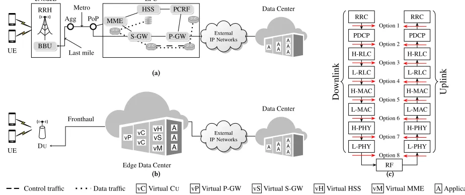
Figure 1: Architectures of a mobile network operator: (a) conventional and (b) MEC realization, and (c) functional split options
inspiration from recent advances in data center transport designs and extends the data center transport to seamlessly incorporate the requirements of the mobile domain. The main novelty of pDCell is to couple the transport protocol with the scheduler of the air interface, residing within the Cu at the edge data center. pDCell vastly improves transport efficiency and can be deployed in a way that is transparent to services and applications by exposing a TCP-compliant socket application interface at the server and mobile terminal side. By coupling the transport congestion control with the wireless scheduler, pDCell can immediately slow down a source sending traffic to a user when radio channel conditions worsen, rather than waiting for slow TCP end-to-end congestion control to adapt. Therefore, buffer sizes in the transport network can be substantially smaller, reducing overall latency.
Our main findings are as follows:
•pDCell significantly outperforms data center transport solu-tions that are not aware of the wireless domain.
•pDCell is scalable, as the increase in network load does not significantly affect the average FCT.
•pDCell operates with minimal queue occupancy and pre-vents unnecessary retransmissions to achieve ultra-low end-to-end latency.
2
MEC ARCHITECTURE AND MOTIVATING
EXAMPLE
2.1
MEC Architecture
2.1.1 Centralized/Cloud-RAN.C-RAN systems split the air
inter-face protocol stack into two separate parts, one that remains at the antenna site called Distributed Unit (Du) and a Centralized Unit (Cu) which is moved to centralized pools in nearby edge data centers. For the operators, C-RAN systems enable significant cost reduction to deploy and maintain antenna sites while boosting the network capacity, e.g., by enabling Cooperative Multi Point tech-niques with tight synchronization between the aggregated cells. The complexity of distributed and central units differs based on
the functions that are processed locally. The different points in the protocol stack where the separation of central and distributed func-tions can take place are calledfunctional splits(see Fig. 1(c)) [8, 12]. The implementation of a given functional split uniquely defines the properties of the system design [2], and of the network connecting the Du and Cu, known as fronthaul (Fh). In the full C-RAN sce-nario, radio I/Q samples are transported in the fronthaul and only circuit-based fiber technology can support the massive capacity required (approximately 1.229 Gbps of CBR traffic per 20 MHz LTE channel, independent from the user traffic) and very low latency requirements (approximately 100µs one way) [14]. With less de-manding splits, such as Packet Data Convergence Protocol/Radio Link Control Protocol (PDCP/RLC) (see Fig. 1(c)), high throughput packet-based fronthaul technologies, such as millimeter-wave or Ethernet, can be used with the caveat that packetization delays need to be taken into account [11]. There is a trade-off between the benefits and drawbacks of using the different functional splits. The nearer to the physical layer the split, the more complex are the signal processing techniques that have to be performed in the Cu, and the higher the potential performance gains and cost savings. At the same time, such lower split options impose very stringent delay and rate requirements on the transport between the Du and Cu. Higher layer functional splits like PDCP/RLC provide some of the benefits of the lower layer splits, such as separation between control and user plane and the possibility of using some joint trans-mission features in order to boost the performance at a much lower transport cost. For the PDCP/RLC split, the transport requirements just include an overhead of around a 20% over the user traffic and easily achievable delays between Du and Cu in the order of ms.
2.1.2 Evolved Packet Core (EPC).The complete set of core
(RRH) DU/RU
UE VM-DU-RU
(BBU) CU NAT
MME SPGW VM-BBU VM-EPC
Skype Youtube
Iperf
UDP UDP
GTP TCP
TCP
SCTP
Figure 2: Setup OpenEPC
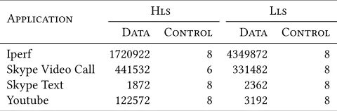
Table 1: Traffic Analysis on OpenEPC for higher (Hls - Op-tion 2) and lower layer splits (Lls - OpOp-tion 6)
Application Hls Lls
Data Control Data Control
Iperf 1720922 8 4349872 8
Skype Video Call 441532 6 331482 8
Skype Text 1872 8 2362 8
Youtube 122572 8 3192 8
component performs specialized functions that are unique to mobile networks and are typically implemented on proprietary hardware. Control and data plane are tightly coupled especially in P-GW and S-GW through a number of dedicated interfaces and protocols. In LTE systems, the GPRS Tunneling Protocol (GTP) is employed to carry data traffic to the end-users. With GTP, end-users maintain the same IP address while moving and traffic is routed between the P-GW and the eNodeB through the S-GW. The Stream Control Transmission Protocol (SCTP) is used for control traffic within the EPC and between the EPC and eNodeB. The recently specified 5G Core redesigns the EPC towards a more de-centralized architecture by instantiating virtual cores in edge data centers through MEC and NFV. In MEC architectures (see Fig. 1(b)), the aforementioned functionalities are virtualized and executed in edge data centers along with pools of Cus performing the radio processing. Although in virtualized environments LTE control signalling can lead to sig-nificant overhead [28], in this work we focus on data delivery of small-size traffic typical in data center and mobile networks [9, 32] where LTE events are executed rarely. To understand traffic char-acteristics of MEC platforms, we experimentally perform traffic analysis on the OpenEPC platform by Core Network Dynamics1. OpenEPC implements a licensed version of the LTE EPC and it is configured as shown in Fig. 2. Several applications were selected for the experiments: bulk transfer through Iperf, Skype call, Skype chat and Youtube video streaming. All experiments run for 60 seconds with different split options, i.e., option 2 and 6 that implement a higher and lower layer functional split. Table 1 shows the traffic, in number of packets, in the mobile network after filtering out ARP, NTP, and DNS traffic. The amount of SCTP control traffic is always extremely low compared to data traffic (carried with TCP Cubic) and is due to HEARTBEAT messages between MME and Cu and the corresponding acknowledgments. The employed functional split does not affect the amount of control traffic. For this reason, in our evaluation we do not take into account mobile network control traffic.
1Accessible from: https://www.openepc.com/
2.2
Motivating Example
Our goal is to design a transport protocol for edge data centers hosting C-RAN virtualized central units (Cus), virtualized EPCs and MEC applications. To minimize end-to-end latency, a transport protocol is required such that packets generated by application servers avoid long queuing delays and arrive at the Cu at the most appropriate point in time for scheduling. The challenge is to achieve simultaneously Gbps of user data rates while supporting low laten-cies. In mobile networks, the MAC layer (see Fig. 1(c)) schedules packets by allocating radio resources in the time and frequency domains. Resources are allocated based on the estimated channel quality of the users. This feedback, known as Channel Quality In-dicator (CQI) reporting, drives the selection of the user bitrate at the Cu. The CQI report has direct relation with the modulation and coding scheme and in turn the transport block size used to allocate physical resource blocks for data transmission to the mobile user. By allowing the Cus to exploit such a feedback and couple it to the edge data center, it becomes possible for the data center transport to perform flow scheduling and to adjust the source sending rate to the amount of radio resources that will be allocated by the mo-bile network, achieving at the same time high data rates and low latency.
10−1 100 101 102 0.0
0.2 0.4 0.6 0.8 1.0
FCT (ms)
CDF
pHost - Limited Queue pHost - Infinite Queue
TCP New Reno
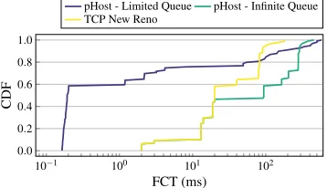
Figure 3: Performance (in term of FCT) of legacy transport protocols in the edge data center scenario
can be on the order of seconds as packets traverse and wait in long queues.
Given the above results, we argue that a new transport needs to be designed specifically for mobile edge data centers. We base this design on data center transport rationale, but parameterize and adapt it to the requirements of the mobile network. The new transport must incorporate specific aspects of the wireless domain and be flexible to adapt to latency and bandwidth variation, while maintaining the benefits of the DCN transport such as low queue occupancy, low FCT and low losses.
3
THE PDCELL TRANSPORT
This section discusses the design rationale of pDCell transport, illustrating how it integrates the data center and wireless domains.
3.1
Assumptions and Design Challenges
We consider an end-to-end architecture where each Du is controlled by one Cu and each mobile user is attached to a single Du at a time. We will discuss in § 5 the modification to the architecture layout necessary to relax such assumption. pDCell has to overcome a number of challenges:
(1) The RTTs of the two components of end-to-end system (mo-bile and data center networks) are different. While future 5G mobile networks should support millisecond RTTs, cur-rent RTTs are in the order of tens of milliseconds to sec-onds [32]. In contrast, the data center delay is in the order of microseconds [13]. Hence, pDCell should take into account this difference and prevent bursts of packets to be queued simultaneously at Cus that will increase latency. To this end, pDCell operates on flow scheduling and source sending rate adaptation in the data center to seamlessly incorporate the requirements of the mobile network.
(2) Multiple data center sources can send traffic to the same mo-bile user simultaneously. The size of such flows can vary and they have to be processed by the Cu hosting the baseband processing of the Du associated with the mobile user. Hence, these flows share the same buffer and compete with flows destined to other users. To minimize FCT, short flows should be prioritized over long ones. Moreover, while the LTE stan-dard requires packet-level guarantees, data center networks only enforce flow level guarantees [28]. To this end, Cus schedule the processing order of incoming data center traffic with a newly defined scheduling policy, explained in § 3.2 and § 3.6.
(3) pDCell should ensure a clear separation between control and data traffic. In edge data centers, both the mobile network control traffic attributed to message exchange between the diverse functionalities of the EPC and the data center control traffic coexist.
(4) While in data centers packet losses are infrequent, in the wireless domain they are common, and hence pDCell should react accordingly depending on the nature of losses. Whereas in the wireless domain pDCell relies on existing mechanisms, in the data center environment pDCell operates on the buffer management level by defining an admission policy that pre-vents packets from being dropped and later retransmitted.
3.2
Architectural Design Overview
In this work, we consider a MEC architecture as in Fig. 1(b), imple-menting a functional split according to option 2 (see Fig. 1(c)). This split limits the multiplexing gains as it leaves a considerable part of the baseband processing at Dus. However, it poses much less strin-gent fronthaul requirements in terms of latency and rate [12, 18], allowing edge data centers and Dus to be interconnected with packet-based technology. To exploit available radio resources, each Du performs resource allocation based on CQI user feedback and takes care of retransmissions if needed (at the RLC and MAC layers). Note that implementing split option 8 would require CQI feedback to be propagated to the Cu, and thus the scheduling is based on less up-to-date channel state information. This is the second advantage of implementing split option 2. However, to solve challenge (1) and perform sophisticated scheduling taking into account simultane-ously data center and mobile networks states, also the Cu needs to be aware of the user channel conditions, which the split option 2 does not provide. Thus, the challenge to solve is: how to propagate such information back to the data center? To resolve this challenge, we resort to buffer management and propose a new mechanism tailored to the requirements of the mobile network.
3.3
Buffer Management at Cus and Dus
Adaptation
Layer
Q1
Q2
Q3
Q4
Q5
Q6
IP PDCP PDU
CU Fronthaul
To DU1
To DU2
Propagation of virtual thresholds
Q1 UE1
Q2 UE2
Q3 UE3
DU1
RLC SDU RLC PDU TB
Q4 UE4
Q5 UE5
Q6 UE6
DU2
Extra buffer space
(a) (b)
Figure 4: Buffering architecture of the wireless domain: (a) each Cu is a shared memory switch with a number of output ports equal to the number of associated Dus; (b) each Du is a shared memory switch with a number of output ports equals to the number of associated users.
the queuing delay can grow up to 540 ms, which is highly detrimen-tal to the performance of interactive applications [21]. To prevent such behaviour, we advocate the a better used of buffer space and we implement the following mechanism for pDCell.
At the Cu level, one queue per user is necessary to control appli-cation sources in the data center. The alloappli-cation is performed by the Radio Resource Control (RRC) protocol when it detects the status of an user as active. The queue size is defined via a virtual threshold that changes based on: i) the feedback from the corresponding Du, ii) the current load at Cu level. Since the sum of the virtual thresh-olds of per-user queues could exceed the processing capacity of the Cu, the buffer space is shared among all per-user queues and the total per-user queue size is adjusted to the processing capacity of the Cu. The number of output ports in this shared memory switch is equal to the number of associated Dus, where outgoing traffic of each port is shaped to the Du processing capacity (see Fig. 4(a)). If for the same user the propagated value from a Du virtual threshold is smaller than the one currently available in the Cu, the latter is decreased. Otherwise, the value of the virtual threshold increases if the current buffer occupancy allows. Similarly to prior work [21], the shared memory switch operates at PDCP level, although for scalability reasons per-user and not per-flow queues are allocated. The natural choice for buffer management in a shared memory switch is a Longest-Queue-Drop (LQD) [4] policy that drops already admitted packets from the longest queue in case of congestion. By design, LQD provides some level of fairness among users to access Cu processing capacity. Since the goal of the transport is to ensure reliability and minimize retransmissions, already admitted pack-ets should not be dropped. Hence, the LQD behavior needs to be modified. When the Cu buffer is full, the virtual threshold of the cur-rently longest queueQis decreased by one unit without dropping packets inQand another incoming packet currently evaluated for admission is simply not admitted. Hence, we guarantee that each admitted packet has buffer space reserved. Furthermore, incoming packets belonging to a user whose queue occupancy is equal to its virtual threshold are also not admitted, regardless of the buffer occupancy. In § 3.7 we will show how to handle retransmission of non-admitted packets to limit non-in-order arrivals and consequent
Before Arrival
Qi
...
Qj p
Incoming Packet
LQD
Qi
...
Qj
B=4
p
Incoming Packet
HTD
Virtual
Threshold Actual QueueOccupancy
=⇒
=⇒
During Admission
=⇒
=⇒
B=4
After Arrival
B=4
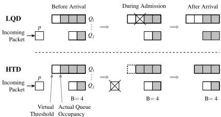
Figure 5: Admission of an incoming packet at Cu. Difference between LQD and the proposed HTD before, during and af-ter admission of a single packet. The size of the Cu buffer B is4.
time-consuming reordering. We call this buffer management policy Highest-Threshold-Decrease (HTD).
Fig. 5 highlights the difference between the LQD and the pro-posed HTD admission controls. Before the new packetparrival, the virtual thresholds of the first and the second queues (QiandQj) are 4 and 2, respectively. The actual queue occupancy ofQi andQj are 3 and 1, respectively. Since the size of the buffer is 4, newly arriving packetptoQjcauses congestion in the Cu buffer. LQD drops one already admitted packet fromQi as it is the longest queue, and admitsptoQj. The virtual thresholds for both queues remain the same. In contrast, HTD never drops an already admitted packet, hence, HTD reduces by one unit the virtual threshold ofQi and preventspfrom being admitted. Note that HTD reacts more slowly than LQD, but satisfies the requirement that admitted packets are never dropped (challenge (4)).
Since each mobile user is controlled by a single Du, each Du main-tains a single queue per user (see Fig. 4(b)). In stationary regime, the queue status att+1 is given as follow:
Q(t+1)=Q(t)+A(t)+R(t) −D(t), (1) whereQ(t)is the queue status at timet,A(t)denotes incoming packets from Cu accepted by the policy HTD,R(t)denotes PDUs to be retransmitted andD(t)corresponds to successfully acknowl-edged PDUs from the mobile user that can be removed from the buffer. Users experiencing good channel quality report a high CQI index, which in turn allows the MAC scheduler to employ higher modulation and coding scheme and transport block size. Hence, the componentD(t)drains the queue fast and the componentR(t)is marginal. In contrast, for users with a low channel quality, the MAC scheduler uses a more robust modulation and coding scheme which reduces the number of bits per resource block. Consequently, the componentsD(t)andR(t)may causeQto grow, limiting the space for new incoming packets. Then Dus propagateA(t)to Cu (using uplink channels) and the corresponding virtual threshold increases if there is room. The propagation ofA(t)makes the Cusindirectly aware of the channel conditions that split option 2 precludes in order to limit/increase the sending rate of data center sources with the adaptation layer (see § 3.5). Note that the size ofQcannot grow indefinitely, i.e., the sum of all allocated per user queues cannot exceed the overall Cu buffer space.
outdated, and the Cu may transmit more traffic than the associated Dus can accept. To accommodate this excess traffic, one solution would be to add extra buffer space, which is however detrimental to interactive applications. Therefore, to avoid allocating this extra buffer for every queue, all virtual per-user queues in Du share the same physical buffer space.
3.4
pDCell Design
The transport design of the mobile network and the data center are transparent to each other. The latter, however, requires to in-corporate mechanisms to reflect specific properties of the wireless environment. In the context of edge data centers, maintaining the data center transport simple to avoid delays introduced by sched-uling is imperative as timeouts and retransmissions negatively impact the overall FCT. Consequently, for pDCell, we rely on trans-ports where flow scheduling, congestion control and reliability are performed by the end hosts, following a minimalistic approach with requests-to-transmit (RTS) and credit assignment. Both are exchanged by end data center servers through credit packets as detailed in § 3.5. The design of pDCell is inspired by previous credit-based transports pHost [17] and ExpressPass [13], and shares the fast start approach common in other recent works [20], i.e., to en-sure low-latency, pDCell sends data packets without completing an handshake procedure by probing for available bandwidth. Specifi-cally, pDCell allows a flow to start by sending data packets along with a requests-to-transmit packet.
In contrast to protocols like pHost and ExpressPass that are specific to data center applications, pDCell is adapted to the unique features of a mobile network as follows. Conventional data center control traffic (credit packets) is exchanged between end hosts and the arrival order of credits at the bottleneck link schedules the subsequent arrival of data packets, which helps to avoid the incast problem. pDCell inherits this property as well, as shown in § 4.1. In MEC architectures, the data traffic needs to traverse Epc hosts before being processed at Cus (challenge (3)). pDCell supports this feature as illustrated in § 3.5.
3.5
The Design of the Adaptation Layer
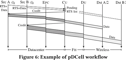
pHost performs transmission control through grant exchange. Each credit packet informs the sender of the next packet (on a packet by packet basis) to be sent for each flow. Hence, pHost effectively per-forms scheduling at a per-packet granularity. pDCell incorporates this design. Similar to pHost and PIAS [7], pDCell makes use of the limited number of priority queues in commodity switches (4-8 per port [7]) to prioritize credit over data packets. Fig. 6 shows the workflow of pDCell for two sources and two destinations and high-lights the traffic exchange between all segments of the considered architecture. A data center source sends an requests-to-transmit packet to inform the adaptation layer at Cu about the estimated flow size along with a small number of data packets. Although some works criticize the availability of precise information on flow sizes [7], it can be estimated [5]. The adaptation layer processes the requests-to-transmit request and admits arriving data packets into the corresponding per-user queue. Implicitly, this will preallocate buffer space in the Cu buffer and will allow to allocate credits on the basis of the difference between the current queue occupancy and
Src A Src B EPC CU DU Dst A Dst B
Datacenter FH Wireless
RTS+
Data RTS+Data Credit PendingRTS list
Credit Data
Data
Figure 6: Example of pDCell workflow
the virtual threshold. Such difference defines the current capability of the mobile user to receive data according to the channel con-ditions. Obviously, the current queue occupancy cannot be larger than the virtual threshold and when the two values are equal, no more credits are generated. Note that this is a conservative ap-proach as more credits could be generated because of the queue turnaround time. Each credit has two associated timerstsandte: the first prevents sources to transmit before the timer expiration and the second prevents sources to transmit data packets after its expiration. If credits expire, i.e., the source does not use them in due time, they are simply re-sent by the destination. By default, we setts =0 andte =ts+1.5×the MTU-sized packet transmission time. Only Cus can updatets, to ensure that only mobile traffic benefits from the adaptation required to solve challenge (1). Con-gestion is detected by Cus when no data packets are received as a reply to a credit packet. Three are multiple possible reasons: i) data packets have not been admitted at the Cu, ii) data packets have been discarded in the network fabric, or iii) the sender has not utilized the token given by credit packets before the expiration ofte. Consequently, pDCell adjuststsasts =TTI+α, where TTI is the Transmission Time Interval andαis the time necessary to transmit A(t)packets at the lowest modulation and coding scheme. In this way pDCell prevents the data center source from sending traffic to the mobile user and this backoff period is set to be sufficient to absorb the already queued traffic.
3.6
Wireless Scheduling Algorithms
Although Dus are in charge ofactualpacket scheduling and map-ping to transport blocks, to pursue specific objectives like FCT minimization the Cus need to select the processing order of in-coming flows. A FIFO approach would naturally process packets according to the arrival time, which can be detrimental for the FCT of small flows. Hence, eachtainterval equal to a frame duration of 1 TTI, the Cus read packets from the buffer B and construct virtual LTE frames to emulate the actual schedule at Dus. Specifically, to each per-user queue (see § 3.3) is assigned a weight and the sched-uler visits queues with high-priority first. This weight is defined as the time it takes to transmit the current flow with the current modulation and coding scheme of the mobile user. The higher the time, the lower the weight.
To assess the impact of the wireless scheduler in the overall framework of pDCell, we propose a new scheduling algorithm and compare its performance against the state-of-the-art:
the wireless domain and the estimated number of packets remaining in the flow. This algorithm optimizes the FCT, especially for small flows and users with good channel qual-ity, providing an advantage to interactive applications. The details of the scheduling algorithm are given in Algorithm 1. •Proportional Fair Scheduler (PFS) preferentially schedules users with good channel quality (while maintaining propor-tional fairness). PFS is commonly implemented in current mobile networks [10] and does not consider the character-istics of the flows to be scheduled. This algorithm ensures fairness among the users and exploits the wireless medium efficiently, hence we employ it as baseline for comparison with MRFS.
Algorithm 1Minimum Remaining Flow Size (MRFS)
1: queue←array of all per-user queues
2: Fa←array of flows at queue ordered by minimum completion time (sizef l ow/bwuser)
3: NQ←number of per-user queues 4: s f ←sub-frame
5: while(size(s f)>0||size(Fa)>0))do
6: for allf in{0,size(Fa)}do
7: fid=Fa[f].id 8: for allqin{1,NQ}do
9: whilef ind(queues(q),fid)!= NU LLdo
10: pk=f ind(queues(q),fid) 11: ifsize(s f)>=size(pk)then
12: S f =[S f ←pk]
13: Fa[f].remaininдpk− − 14: end if
15: end while
16: end for
17: end for
18: end while
The choice of the employed scheduling algorithm allows to fulfill specific goals. To understand the rationale behind the MRFS design, let us consider the following example. Two sources in the data center S1,S2send two flows each to two mobile users Ue1and Ue2served by the same Cu. Assume CQIUe1>CQIUe2and the paths between
S2and Cu to experience congestion while the paths betweenS1 and Cu do not. ConsiderFS1Ue1 <FS1Ue2andFS2Ue1 >FS2Ue2 withFS1Ue1 andFS2Ue2 to be of equal size. Then, to minimize overall FCT, the transport should schedule in orderFS1Ue1,FS2Ue2, FS1Ue2andFS2Ue1.
Given the preference that MRFS gives in scheduling first short flows, long ones can be starved in the short term. By penalizing fairness and giving high priority to short flows, we ensure to meet latencies required for URLLC type of traffic. Note that in the long term, the long flows getactuallyscheduled because, as their re-maining flow size becomes smaller, in turn their scheduling priority increases.
3.7
Handling Packet Losses
Although the credit-based scheme is designed to minimize packet losses and has been proven to ensure almost zero losses in data
centers, in an end-to-end architecture this is not true anymore. In mobile networks, packet losses are more frequent because of the inherent characteristics of the wireless channel. Consequently, pDCell considers the different nature of packet losses and provides different reaction mechanisms.
In the data center, HDT (see § 3.2) ensures reliability by not dropping already admitted packets. When data packets are not admitted at the Cu or lost, credit packets, which include the ID of the next data packet to be sent, are issued again. This also limits out-of-order arrivals and the consequent reordering that is detrimental for interactive applications.
In the wireless domain, pDCell relies on existing reliability mech-anisms implemented in mobile networks, namely the Automatic Repeat Request (ARQ) and the Hybrid ARQ (HARQ) at the RLC and MAC layer respectively. Hence, the mobile users do no propa-gate explicit per-packet feedback to the Cus, which would require either modifications to the existing protocols through explicit sig-naling over uplink control channels or adopting a technology- and split-dependent eCPRI solution that estimates HARQ timeouts. Fur-thermore, because of the combined effect of HDT and MRFS, mobile users with bad channel quality signal implicitly this status to data center sources, which in turn slow down and reduce the sending rate to prevent that significant amount of traffic to incur in high loss probability.
4
EVALUATION
This section evaluates pDCell for a MEC setting composed of a edge data center and wireless domain by means of simulations. Our evaluation setup builds on the one used for previous works [6, 17] and publicly available2by extending it to incorporate the mobile network component.
4.1
Evaluation Methodology
Network Topology: The network topology spans from the DCN to the cellular network. The latter consists of LTE cells configured with a 20 MHz channel and 4×4 MIMO, providing up to 100 Mbps of user-plane data. A set of 100 LTE category 3 UEs are randomly located in the area of coverage. The channel model and the UE link quality measurement report follow [15]. The functional split is according to the 3GPP functional split 2. The fronthaul interface is modeled as a serial line of 10 Gbps. For CQI reports, we employ traces reported in [16] and assume a reporting interval of 5 ms, which is the typical value used in LTE to carry the CQI feedback over the Physical Uplink Shared Channel under fading conditions [3].The CQI feedback is used by the Du to determine the modulation and coding scheme for data transmissions to the end user.
As in prior work [6, 17], the DCN is a two-tier leaf-spine topol-ogy comprising 144 servers grouped into 9 racks. Unlike large cloud data centers hosting hundreds of thousands of servers, edge data centers for baseband processing are expected to be of a smaller size [31]. Interconnectivity between the computing servers and the 4 core switches is provided by 9 top-of-rack (TOR) switches through a full mesh. As a result, the data center network is a non-oversubscribed topology where each TOR has 16 10 Gbps links
103 104 105 106
0.0 0.2 0.4 0.6 0.8 1.0
Flow size (Bytes)
CDF
Figure 7: Distribution of flow sizes of data center traffic to the Cu
100 101 102 103
0.0 0.2 0.4 0.6 0.8 1.0
Time (ms)
CDF
Non Incast Incast
Figure 8: FCT with different traffic matrices
towards the servers and 4 40 Gbps towards the core switches. Both core and TOR switches implement packet spraying and are equipped with tiny per-port buffers of 36 KB each. The DCN in-cludes as hosts Cu and distributed EPC to be compliant with § 2.1.1 and the latest technology developments [19].
The wireless scheduler decides which packets are transmitted to the Du and it works on the time scale of frequency-division duplex (FDD) sub-frames (1 ms).
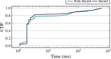
Workloads: The data center workloads used in the evaluation exploit a flow size distribution based on measurements in a production data center with similar topology as in our study and from a cluster running data mining type jobs [9]. Fig. 7 shows the CDF of the flow size. Most of the flows are small (≤10 KB), while a limited number of long flows contain most of the traffic (the largest flow is 3 MB and 1 GB for production data center and cluster respectively). The flow size distribution is consistent with measurements of cellular network traffic [25]. To test the impact of background traffic (i.e., traffic generated by other applications hosted in the data center) on mobile traffic, we perform the following experiment. Similar to previous works [6, 17], the flow arrival follows a Poisson process with a rate that ensures a given target network load set by default to 0.6. As explained in § 3.4, pDCell inherits the incast avoidance of credit exchange based DCN transport protocols, i.e., no throughput degradation is perceived when multiple sources make concurrent requests to send data to the same receiver simultaneously. To eval-uate this property, we compare the CDF of the flow completion time under two different traffic matrices. In thenon-incastone, 20% of the flows are destined to a single Cu server, while the re-maining flows are exchanged between random hosts in the data center. In theincasttraffic matrix, all sources send traffic to the same Cu server. Fig. 8 compares the completion time of the flows. The CDF shows negligible differences for the two traffic matrices. Consequently, in the remainder of the paper, we present results for
10−2 10−1 100 101 102 103 104 105
0 0.2 0.4 0.6 0.8 1
Time (ms)
CDF
pDCell - MRFS pDCell - PFS pHost TCP New Reno
Figure 9: Distribution of FCT for pDCell, pHost and TCP
a single Cu, which can be extrapolated to scenarios where several Cus are located in the same edge data center.
Performance Metrics: To evaluate pDCell, we adopt FCT as main performance metric, i.e., the time between the first packet being sent and the last one being received of a given flow. In the rest of the paper the FCT is measured end-to-end and not only within the data center. Hence, lower values of the slowdown indicate better system performance. We assess and discuss the effect of buffer size at the Cu and its implication on FCT. To evaluate the impact of the protocol in the wireless domain, we analyze the FCT of flows of users with different channel quality, e.g., users located near the edge of the cell versus users located near the base station.
4.2
Results
The first experiment compares the FCT of pDCell against solu-tions that are not aware of the wireless domain requirements at the congestion control protocol level. Specifically, Fig. 9 compares performance of pDCell with the different scheduling algorithms illustrated in Section 3.6 against TCP New Reno and legacy pHost in the data center domain, both employing the PFS scheduler. We observe that pDCell, being aware of the wireless network status, outperforms significantly the other solutions regardless the em-ployed scheduling algorithm. Focusing on pDCell performance, the MRFS scheduling algorithm consistently reduces FCT with respect to PFS. In particular, small flows for users with good quality benefit the most from MRFS as they are scheduled immediately in the next frame after arrival at Cu. PFS instead, treats all users and flows the same way, using sub-optimally the bandwidth of the cellular network and increasing the overall FCT for all flows.
10−1 100 101 102 0.0
0.2 0.4 0.6 0.8 1.0
Time (ms)
CDF
MRFS-Trace-based CQI PFS-Trace-based CQI
MRFS-Fix-CQI PFS-Fix-CQI
(a) Effect of CQI reports on MRFS and PFS
MRFS PFS
100 101 102 103
FCT
(ms)
1≤CQI<6 7≤CQI<10 10≤CQI≤15
(b) FCT of short flows Figure 10: Analysis of FCT for users experiencing different channel quality
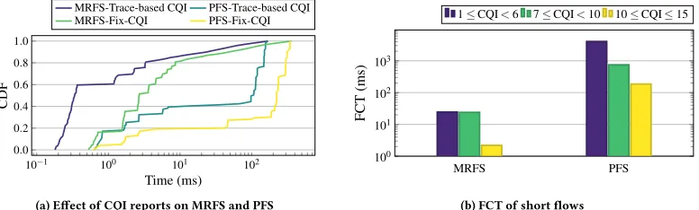
to the users’ channel quality. Specifically, users with CQI values in the range 1≤CQI<6 experience a bad channel quality and use QPSK modulation, users with 7≤CQI<10 use 16QAM, while users experiencing good channel quality with 10≤CQI≤15 use 64QAM. MRFS with its awareness of channel quality statistics and remaining flow size significantly outperforms PFS. In particular, the FCT achieved by users experiencing bad channel quality improves by 2 orders of magnitude compared with PFS. Interestingly, while the dependence between the FCT and user CQI of PFS is linear, in MRFS is not. The reason is that, by design, MRFS always chooses to schedule first flows with minimum remaining size of users in favorable channel conditions.
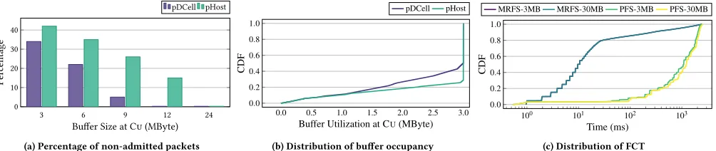
The next set of experiments measures FCT performance of pDCell while varying the amount of buffer space at the Cu for both sched-ulers. To achieve ultra-low latency, it is essential that flows en-counter small queuing delays along the path to the end user. Fig. 11(a) shows the percentage of non-admitted packets and compares the performance of pDCell and pHost for different buffer sizes. The for-mer, by leveraging information on user-perceived channel quality, slows down application sources by reducing the fraction of non-admitted packets that have to be rescheduled. In contrast, pHost application sources sending rates do not adapt to the user-perceived channel quality and keep pushing traffic to Cus’ buffers, who fill up quickly and maintain a high percentage of non-admitted packets. This negatively impacts the FCT. Fig. 11(b) analyzes buffer utiliza-tion after having set the maximum Cu buffer size at 3 MB. Note that the Cu buffer size is shared among all the users and flows, hence the 3 MB buffer corresponds to an average per flow buffer of only two packets. pHost reaches quicker than pDCell the full buffer occupancy which it then maintains for the entire simulation period. pDCell after the initial period where the queue fills up, achieves lower full buffer utilization. Hence, it reduces the fraction of non-admitted packets and improves consequently FCT. Fig. 11(c) shows that FCT values remain very similar when the buffer size varies from 3 to 30 MB for both schedulers. These results show that the performance of pDCell remains very similar for a wide range of values and can operate at very low buffer sizes, independently of the choice of scheduler.
5
PERSPECTIVES FOR IMPLEMENTATION IN
5G SYSTEMS
The system enhancements proposed and evaluated so far are appli-cable to MEC architectures for current LTE mobile networks and
next 5G systems with users attached to one Du at a time. Next, we show that minimal modifications need to be performed to the buffering architecture to support multi-connectivity.
In 3GPP Release 12, the concept of dual-connectivity was in-troduced. A UE can be simultaneously connected to two eNodeBs, one master (MeNB) and a secondary (SeNB). The MeNB handles both control and user plane, while the SeNB typically handles the user-plane only by providing additional resources. For 5G systems, the concept of dual-connectivity evolved into multi-connectivity where a UE can be simultaneously attached to a LTE eNodeB and a 5G next generation eNodeB (gNB). The 3GPP Release 15 defines the concepts of 5G new radio (NR) and provides the basis for inter-networking among LTE and NR [29]. Leveraging the PDCP/RLC split, user-plane traffic can be split or duplicated with packet du-plication at the aggregation point (the PDCP layer) in the Cu [27]. Then, traffic undergoes separate procedures on the lower-layer pro-tocols, and UEs can individually benefit from separate scheduling, transmission on different frequencies, and reliability schemes.
The buffer management architecture in § 3.2 can support multi-connectivity with minimal modifications. The number of per-user queues at the Cu is not longer one per Du (see Fig. 4), but the RRC protocol will allocate two queues to each active user, one for MeNB and a second one for the SeNB. Since traffic for each Du is scheduled on a different output port of the shared memory switch and multiple per-user queues are allocated at the Cu, the update of virtual thresholds at the Du is driven by both the CQI from the user side and feedback from the Cu.
6
CONCLUSION
3 6 9 12 24 0
10 20 30 40
Buffer Size at Cu (MByte)
Per
centage
pDCell pHost
(a) Percentage of non-admitted packets
0.0 0.5 1.0 1.5 2.0 2.5 3.0 0.0
0.2 0.4 0.6 0.8 1.0
Buffer Utilization at CU(MByte)
CDF
pDCell pHost
(b) Distribution of buffer occupancy
100 101 102 103
0.0 0.2 0.4 0.6 0.8 1.0
Time (ms)
CDF
MRFS-3MB MRFS-30MB PFS-3MB PFS-30MB
(c) Distribution of FCT Figure 11: Analysis on buffer size at Cu
it vastly reduces FCT, which makes our solution a prerequisite for ultra-low latency applications.
ACKNOWLEDGMENT
This work is partially supported by the European Research Council grant ERC CoG 617721, the Ramon y Cajal grant from the Spanish Ministry of Economy and Competitiveness RYC-2012-10788, by the European Union H2020-ICT grant 644399 (MONROE), by the H2020 collaborative Europe/Taiwan research project 5G-CORAL (grant num. 761586) and the Madrid Regional Government through the TIGRE5-CM program (S2013/ICE-2919). Further, the work of Dr. Kogan is partially supported by a grant from the Cisco Uni-versity Research Program Fund, an advised fund of Silicon Valley Community Foundation.
REFERENCES
[1] 3GPP RAN3. 2016. TS 36.306. [2] 3GPP RAN3. 2017. TR 38.801 V14.0.0. [3] 3GPP RAN3. 2018. TS 36.521-1 V15.2.0.[4] William Aiello, Alexander Kesselman, and Yishay Mansour. 2008. Competitive buffer management for shared-memory switches.ACM Trans. Algorithms5, 1 (2008), 1–16. https://doi.org/10.1145/1435375.1435378
[5] Mohammad Al-Fares, Sivasankar Radhakrishnan, Barath Raghavan, Nelson Huang, and Amin Vahdat. 2010. Hedera: Dynamic Flow Scheduling for Data Center Networks. InProc. USENIX NSDI. 281–296.
[6] Mohammad Alizadeh, Shuang Yang, Milad Sharif, Sachin Katti, Nick McKeown, Balaji Prabhakar, and Scott Shenker. 2013. pFabric: Minimal Near-optimal Dat-acenter Transport. InProc. ACM SIGCOMM. 435–446. https://doi.org/10.1145/ 2486001.2486031
[7] W. Bai, L. Chen, K. Chen, D. Han, C. Tian, and H. Wang. 2017. PIAS: Practical Information-Agnostic Flow Scheduling for Commodity Data Centers.IEEE/ACM Trans. on Networking25, 4 (Aug 2017), 1954–1967. https://doi.org/10.1109/TNET. 2017.2669216
[8] J. Bartelt, P. Rost, D. Wubben, J. Lessmann, B. Melis, and G. Fettweis. 2015. Fronthaul and backhaul requirements of flexibly centralized radio access net-works. IEEE Wireless Communications22, 5 (Oct 2015), 105–111. https: //doi.org/10.1109/MWC.2015.7306544
[9] Theophilus Benson, Aditya Akella, and David A. Maltz. 2010. Network Traffic Characteristics of Data Centers in the Wild. InProc. ACM IMC. 267–280. https: //doi.org/10.1145/1879141.1879175
[10] F. Capozzi, G. Piro, L. A. Grieco, G. Boggia, and P. Camarda. 2013. Downlink Packet Scheduling in LTE Cellular Networks: Key Design Issues and a Survey. IEEE Communications Surveys and Tutorials15, 2 (Second 2013), 678–700. https: //doi.org/10.1109/SURV.2012.060912.00100
[11] C. Y. Chang, N. Nikaein, and T. Spyropoulos. 2016. Impact of Packetization and Scheduling on C-RAN Fronthaul Performance. InProc. IEEE GLOBECOM. 1–7. https://doi.org/10.1109/GLOCOM.2016.7841885
[12] A. Checko, A. P. Avramova, M. S. Berger, and H. L. Christiansen. 2016. Evaluating C-RAN fronthaul functional splits in terms of network level energy and cost savings. Journal of Communications and Networks18, 2 (Apr 2016), 162–172. https://doi.org/10.1109/JCN.2016.000025
[13] Inho Cho, Keon Jang, and Dongsu Han. 2017. Credit-Scheduled Delay-Bounded Congestion Control for Datacenters. InProc. ACM SIGCOMM. 239–252. https: //doi.org/10.1145/3098822.3098840
[14] A. de la Oliva, J. A. Hernandez, D. Larrabeiti, and A. Azcorra. 2016. An overview of the CPRI specification and its application to C-RAN-based LTE scenarios.IEEE
Communications Magazine54, 2 (Feb 2016), 152–159. https://doi.org/10.1109/ MCOM.2016.7402275
[15] Ayman Elnashar and Mohamed A El-Saidny. 2013. Looking at LTE in practice: A performance analysis of the LTE system based on field test results. IEEE Vehicular Technology Magazine8, 3 (2013), 81–92. https://doi.org/10.1109/MVT. 2013.2268334
[16] Jose Oscar Fajardo, Ianire Taboada, and Fidel Liberal. 2015. Analysis of CQI Traces from LTE MIMO Deployments and Impact on Classical Schedulers. In Wired/Wireless Internet Communications. 60–73.
[17] Peter X. Gao, Akshay Narayan, Gautam Kumar, Rachit Agarwal, Sylvia Rat-nasamy, and Scott Shenker. 2015. pHost: Distributed Near-optimal Datacen-ter Transport over Commodity Network Fabric. InProc. ACM CoNEXT. 1–12. https://doi.org/10.1145/2716281.2836086
[18] A. Garcia-Saavedra, J. X. Salvat, X. Li, and X. Costa-Perez. 2018. WizHaul: On the Centralization Degree of Cloud RAN Next Generation Fronthaul.IEEE Trans. on Mobile Computing(2018). https://doi.org/10.1109/TMC.2018.2793859 [19] Fabio Giust, Gianluca Verin, Kiril Antevski, Joey Chou, Yonggang Fang, and
Walter Featherstone et al. 2018. MEC Deployments in 4G and Evolution Towards 5G. ETSI White Paper.
[20] Mark Handley, Costin Raiciu, Alexandru Agache, Andrei Voinescu, Andrew W. Moore, Gianni Antichi, and Marcin Wójcik. 2017. Re-architecting Datacenter Networks and Stacks for Low Latency and High Performance. InProc. ACM SIGCOMM. 29–42. https://doi.org/10.1145/3098822.3098825
[21] R. Kumar, A. Francini, S. Panwar, and S. Sharma. 2018. Dynamic Control of RLC Buffer Size for Latency Minimization in Mobile RAN. InProc. IEEE WCNC. 1–6. https://doi.org/10.1109/WCNC.2018.8377190
[22] Y. Lu, G. Chen, L. Luo, Y. Xiong, X. Wang, and E. Chen. 2017. One More Queue is Enough: Minimizing Flow Completion Time with Explicit Priority Notification. InProc. IEEE INFOCOM. 1–9. https://doi.org/10.1109/INFOCOM.2017.8056946 [23] Mobile Edge Computing (MEC) ETSI Industry Specification Group (ISG). 2017.
Radio Network Information API.
[24] Binh Nguyen, Arijit Banerjee, Vijay Gopalakrishnan, Sneha Kasera, Seungjoon Lee, Aman Shaikh, and Jacobus Van der Merwe. 2014. Towards Understanding TCP Performance on LTE/EPC Mobile Networks. InProc. ACM All Things Cellular. 41–46. https://doi.org/10.1145/2627585.2627594
[25] U. Paul, A. P. Subramanian, M. M. Buddhikot, and S. R. Das. 2011. Understanding traffic dynamics in cellular data networks. InProc. IEEE INFOCOM. 882–890. https://doi.org/10.1109/INFCOM.2011.5935313
[26] Jonathan Perry, Amy Ousterhout, Hari Balakrishnan, Devavrat Shah, and Hans Fu-gal. 2014. Fastpass: A Centralized "Zero-queue" Datacenter Network. InProc. ACM SIGCOMM. 307–318. https://doi.org/10.1145/2619239.2626309
[27] J. Rao and S. Vrzic. 2018. Packet Duplication for URLLC in 5G: Architectural Enhancements and Performance Analysis. IEEE Network32, 2 (March 2018), 32–40. https://doi.org/10.1109/MNET.2018.1700227
[28] M. T. Raza, D. Kim, K. H. Kim, S. Lu, and M. Gerla. 2017. Rethinking LTE network functions virtualization. InProc. IEEE ICNP. 1–10. https://doi.org/10.1109/ICNP. 2017.8117554
[29] J. Sachs, G. Wikstrom, T. Dudda, R. Baldemair, and K. Kittichokechai. 2018. 5G Radio Network Design for Ultra-Reliable Low-Latency Communication.IEEE Network32, 2 (Mar 2018), 24–31. https://doi.org/10.1109/MNET.2018.1700232 [30] M. Shafi, A. F. Molisch, P. J. Smith, T. Haustein, P. Zhu, P. De Silva, F. Tufvesson, A.
Benjebbour, and G. Wunder. 2017. 5G: A Tutorial Overview of Standards, Trials, Challenges, Deployment, and Practice.IEEE JSAC35, 6 (Jun 2017), 1201–1221. [31] Chanh Nguyen Le Tan, C. Klein, and E. Elmroth. 2017. Location-aware load
prediction in Edge Data Centers. InIEEE FMEC. 25–31. https://doi.org/10.1109/ FMEC.2017.7946403