5 |
P a g e
STUDY ON FAILURE OF HIGH EMBANKMENT IN
ROAD WORK ON MARSHY AREA AND
RECTIFICATION WORKS BY IMPLEMENTATION
OF GROUND IMPROVEMENT TECHNIQUES
SPECIFIC TO THE GROUND CONDITION
Nishanth.B.S
1, Arun Prabha
2, Chethan Kumar N T
31
Sr. Manager, Mangalore SEZ Limited, Mangaluru, Karnataka (INDIA)
2Sr.Professional Engineer (ECI), Principal Consultant, Projectile, Mangaluru, Karnataka (INDIA)
3Assistant Professor, Civil Engineering Department, SCEM, Mangaluru, Karnataka(INDIA)
ABSTRACT
The rapid urbanization and industrial development have resulted in scarcity of prime land. Some road works
having a new alignment have to transverse at locations which are not suitable on foundation criteria. The
success of geotechnical works on soft ground relies on important factors such as proper planning, analysis,
design, construction control and supervision. In case of failure to comply with any one of the above or the
combination of the above factors, there are failures of geotechnical works such as embankment, approaches to
bridges and culverts. The embankment in case of a high fill in a marshy area need to be reinforced by ground
improvement techniques. Several ground improvement techniques widely used are vibro compaction, vibro
displacement compaction techniques which are area specific. Other than additional measures like
reinforcement, filter, drainage, separation layer using Geo-synthetics is also employed. A combination of both
may also be utilized on case to case basis.
In this study, the project area is a marshy water logged area having very low SBC value (almost nil) and which
needs to be filled with earthen embankment for the purpose of approach road connectivity joining an ROB
crossing Konkan Railway. The high embankment was earlier compacted and filled for a length of 75 m, but
failed due to shear cracks. The aim of the project is to improve the foundation of the embankment, considering
its weak nature by utilizing multiple ground improvement techniques like stone column and geo-grid in
combination.
The study revealed that the embankment rested on the foundation of stone column and geo-grid in a marshy
area has withstood the failure of the high fill embankment without any deformations.
Key words: Embankment, Geo-Grid, Stone Column.
I. INTRODUCTION:
India has a very long coastline from the Gulf of Kutch to Sunderbans for an approximately length of 7500 kms.
Recently large scale development has been observed in the coastal due to the emergence of new ports,
expansion of ports with the entry of private players into the otherwise controlled government market. The ports
form the basis for cheapest form of transportation for long haulages of goods and seamless connectivity to ports
6 |
P a g e
deposits in the sub profile particularly along the coast in narrow tidal area and swamp area. These deposits occurin the backwater areas which are soft clays have low shear strength and high compressibility. In some instances,
due to shortage of land or other constraints, construction activity have to be carried out in such areas which can
lead to construction failures and danger to human life and property if proper precautions are not taken.
In order to make soil suitable for use of construction activity, ground improvement techniques need to be
employed depending on the usability of the service, site condition, surrounding environment, time constraints
and budgetary constraints. The generally adopted ground improvement practices are stabilization by mechanical,
chemical and cementing means, compaction, drainage methods, vibration methods, grouting, compaction,
pre-compression, use of geo-synthetics etc. depending on the above mentioned factors. In certain scenarios, a
combination of more than one ground improvement technique may be adopted to achieve desired result.
This project study pertains to development of a 2-lane road from Kana Junction in Surathkal area to Jokatte. It
is reported that the embankment was sinking and remedial measures need to be undertaken to address the issue.
The road being built is traversing through marshy land near Jharandaya temple in Thokur and thereafter on
western side of Konkan Railway till Jokatte. This marshy land is caused due to the backwater of Gurpur river
which exhibit heavy salt content due to the presence of the Arabian sea in the vicinity. While constructing the
earthen embankment, the soil in about 75 m stretch on one side of the road has sunk to an extent of 3 m and
some cracks are also seen on balance portion of this stretch. Since the cost of embankment by reinforcing the
ground conditions or construction of bridge in marshy area was uneconomical, the constructed embankment was
re-laid by spreading and compacting the existing embankment soil and then increasing the width of embankment
base by additional 30-50m and construct the embankment by doing proper compaction layer by layer and
providing horizontal berm with extra earth to prevent sliding on the edges. However the embankment failed due
to development of shear cracks being developed in spite of additional width of the base width of the
embankment formation.
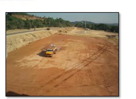
Embankment snapshot and photos after embankment failure after initial construction activity
7 |
P a g e
Snapshot after embankment failure after
additional widening of the base
Site Photo of Embankment failure for
Additional Embankment toe width
Site Photo of Embankment failure (Sliding & Shear) for Additional Embankment toe width
II. OBJECTIVES:
The main objective of the project is
To determine the causes for failure of the embankment in spite of providing additional base width to
counter the sliding of the embankment
Suggest suitable measures to arrest the failure and stabilize the embankment by application of suitable
8 |
P a g e
III. MATERIALS AND TESTING:
The materials used for execution of the work were fine aggregates (river sand), soil (Lateritic), coarse
aggregates (crushed granite) & biaxial geo-grid.
Fine aggregates (river sand)
The material use as fine aggregate is river sand sourced from Adyar, Netravati River in Mangaluru. The river
sand was used to form a drainage blanket layer which had the following geo-technical properties. 1) Specific
Gravity: 2.6, 2) Sieve Analysis : Zone-II criteria, 3) Deleterious Material: Nil, 4) Clay lumps : 2.5 %, 5)
Material finer than 75 micron : 1 %.
Soil
The materials used for embankment purpose were lateritic soil sourced from two nearby locations (borrow pits)
near Kodikere area (Source 1) which had the following properties 1) OMC : 15 %, 2) MDD : 1.82 gm/cc, 3)
Free Swell Index : 23 %, Soaked CBR Value : 14.5 % and Jokatte area (Source 2) which had the following
properties 1) OMC : 14 %, 2) MDD : 1.80 gm/cc, 3) Free Swell Index : 8 %, Soaked CBR Value : 15.8 %.
Coarse aggregates (crushed granite)
The material used were primarily 40 mm downsize aggregates sourced from stone quarries near Permude and
was used as the main ingredient of stone column with a fineness modulus of 7.42.
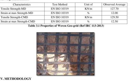
Bi-axial geogrids
A woven Bi-Axial Geo-grid sourced from MACCAFERRRI was used based on the requirements with the
following characteristics.
Characteristics Test Method Unit of
Measurement
Observed Average Value
Tensile Strength-MD EN ISO 10319 KN/m 127.70
Strain at max Strength-MD EN ISO 10319 % 12.00
Tensile Strength-CMD EN ISO 10319 KN/m 129.50
Strain at max Strength-CMD EN ISO 10319 % 12.50
Table 3.1 Properties of Woven Geo-grid (Ref IRC 113-2013)
IV. METHODOLOGY
4.1 Problem Identification
This marshy land is caused due to the backwater of Gurpur river which exhibit heavy salt content due to the
9 |
P a g e
stretch on one side of the road has sunk to an extent of 3 m and some cracks are also seen on balance portion ofthis stretch. In the present situation it is not possible to take any heavy equipments or vehicles on top of the
embankment and do the remedial measures. It is required to strengthen/improve the foundation soil below the
embankment.
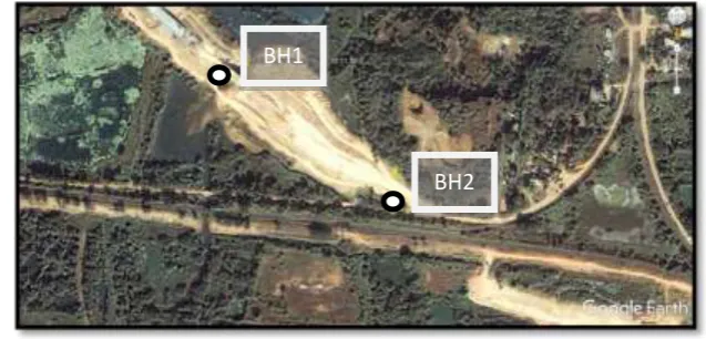
4.2 Collection Of Sample And Testing & Analysis Of Failure:
Borehole samples were collected from two locations at original ground level on extreme ends to determine the
cause.
Fig 4.1 Borehole Location Map
The Borehole location is as follows:
BH1 - 12°57'50.28"N 74°50'11.86"E (NEAR BRIDGE)
BH2 - 12°57'45.96"N 74°50'17.84"E (NEAR RAILWAY TRACK EMBANKMENT)
The bore log near the approach area (BH1), indicate very low „N‟ values (observed blow counts from SPT test)
up to almost 10 m depth. This low blow Count values indicate that the soil at top 10m is very weak (meaning
very very low bearing capabilities and high compressibility‟s), soft and under-consolidated; and water table
indicated is also high (1 m below the existing ground level). The soils are identified as fine grained soils,
clayey/silty. The height of embankment constructed is 10 to 11 m, with side slopes of l.5H:1V. This imposes a
load on the weak foundation soil in excess of 200 kN/m2 which the weak foundation soil cannot sustain. This is
reflected as a bearing capacity (shear) failure as seen from the large settlements of nearly 3 metre beneath the
embankment, and also very significant ground heave at the toe.
4.3 Suggestions
It is suggested to remove the entire embankment soil for this stretch and do the ground improvement of the
foundation soil by stone columns and drainage layer and layer separation by using geo-synthetics.
4.4 Remedial Measures Undertaken
i)
Excavation of entire embankment soil by mechanical means using hydraulic excavator of
1.0 cum capacity and disposal by tippers of not less than 10 cum capacity.
10 |
P a g e
ii)
Marking of co-ordinates on field and boring of 1.0m dia pile using casagrande B 170
rotary drill at 3.0 d spacing centre to centre in a triangular pattern (713 piles).
iii)
Driving of retractable mild steel liner
casing of 6.0 mm thickness with top
collar with derick and winch machinery.
iv)
Stockpiling of granite metal of varying
size aggregates from 40 mm downsize.
v)
Providing & filling bored pile with
granite metal of varying size from 40
mm downsize with top feed system using
backhoe loader.
11 |
P a g e
vii)
Laying of bi-axial geo-grids.
viii)
Laying of drainage blanket of 0.45m thick consisting of clean sand.
ix)
Construction of embankment with compacting in layers of 200mm thick using good
quality lateritic soil.
12 |
P a g e
xi)
Providing horizontal berms at every 6.0 vertical heights with width of berm at 2.0 m.
xii)
Turfing of embankment slope as additional protection measure.
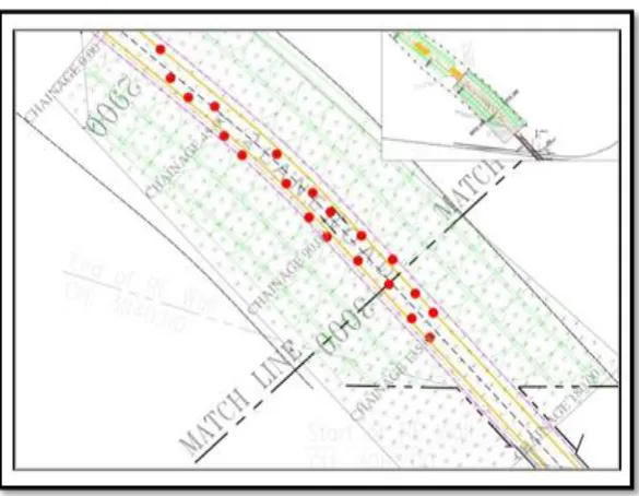
Area layout drawing
General Cross-section of Embankment
13 |
P a g e
V. RESULTS
5.1 General
To assess the efficiency of ground improvement techniques the conventional in situ test are used. The most
popular tests in situ test to assess the efficiency of ground improvement are SPT test, CPT test and Plate load
test. The SPT tests are carried out all along the longitudinal direction of the carriageway to determine the
stability of the filled up embankment on the stone column and Geo grid against sliding and shear failure. The
SPT results will enable us to determine the type of compaction and the range of relative density and the friction
angle achieved in the compacted embankment fill.
Correlation between SPT-N value, Friction angle and Relative Density (Meyerhoff 1956)
SPT Soil Packing Relative Density (%) Friction angle(°)
< 4 Very Loose < 20 <30
4 – 10 Loose 20 – 40 30 -35
10 – 30 Compact 40 – 60 35 – 40
30 – 50 Dense 60 – 80 40 – 45
>50 Very Dense
>80 >45
Table 5.1 Correlation Data
14 |
P a g e
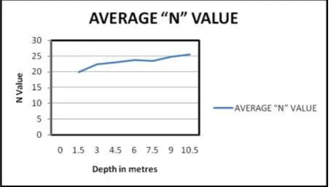
Average “N” value recorded across all 20 bore holes in SPT test
LVL N value
0.00 19.90
1.50 19.90
3.00 22.40
4.50 23.00
6.00 23.80
7.50 23.50
9.00 24.80#
10.50 25.50*
Table 5.2 Average N Value across all Boreholes in Road Alignment
#5 boreholes
*4 boreholes
Fig 5.1 Average “N” value Chart for depth of filling
As detailed in Table 5.1 pertaining to relation between SPT-N value, Friction angle and Relative Density the
following inference is made based on the average N value.
The N Value average across 20 boreholes indicate a compacted soil packing with a range of 40-60 % in relative
15 |
P a g e
VI. CONCLUSION & FUTURE SCOPE
The aim of this project was to determine the suitability of ground improvement techniques in combination of
stone columns and Geo-grid application. The emphasis was to determine the applicability of this combination in
a water logged salt intrusion area susceptible to change in water level.
Based on the in-situ analysis performed at site after the construction of the embankment on the improved ground
sub-surface conditions, the following conclusions are arrived at.
a) The ground improvement technique has substantially increased the “N value” and the S.B.C of the
sub-surface soil.
b) The use of intermediate sand layer has been able to thwart the effect of high water table.
c) The use of Woven Geo-grid as a basal reinforcement layer has provided sufficient resistant to tension
and has withheld the embankment fill intact preventing it from shear failure and sliding which had
occurred in earlier instances without the use of ground improvement technique.
d) The combination of this ground improvement technique with embankment filling is far more
economical than road on structural components.
The ground improvement technique combination of stone column with Geo-grid can be modified with alternate
forms of Geo-synthetic membranes as per the site condition & the purpose to be served.
REFERENCES
[1]. A.P. Ambily, S.R. Gandhi, “Experimental & Theoretical Evaluation of Stone Column in Soft Clay” –
ICGGE 2004.
[2]. Kul Bhushan et.al, “Ground Improvement by Stone Columns and Surcharge at a Tank Site”, International
Conference on Case Histories in Geotechnical Engineering Apr 13th - Apr 17th (2004).
[3]. Georg Heerten, “Improving the Bearing Capacity of Soils with Geo synthetics”, Improvement of Soil
Properties, Bratislava on June 4 – 5, 2007.
[4]. Gohil D.P. et.al, “APPLICATION OF GEOSYNTHETICS FOR GROUND IMPROVEMENT: AN
OVERVIEW”, IGC 2009, Guntur, INDIA.
[5]. Kousik Deb, “A mathematical model to study the soil arching effect in stone column-supported
embankment resting on soft foundation soil”, Applied Mathematical Modeling, April 2011.
[6]. Ahmed Farouk , Marawan M. Shahien, “Ground improvement using soil–cement columns: Experimental investigation”, Alexandria Engineering Journal- September 2013.
[7]. Sneha P. Hirkane, N. G. Gore, P. J. Salunke, “ Ground Improvement Techniques”, International Journal of
Inventive Engineering and Sciences (IJIES) ISSN: 2319–9598, Volume-2, Issue-2, January 2014.
[8]. Gaafer,Manar, Bassioni,Hesham, Mostafa,Tareq, “Soil Improvement Techniques”, International Journal of
Scientific & Engineering Research, Volume 6, Issue 12, December-2015.