National Conference on Advances in Engineering and Applied Science (NCAEAS) 29th January 2018
Organized by : Anjuman College of Engineering and Technology (ACET) Nagpur, Maharashtra, India, In association with
International Journal of Scientific Research in Science and Technology
“Comparative Analysis of Multi-Storey Building with Base
Isolation Under Seismic Loading.”
Bhavesh Ninawe1, Ahmad Raza1,Amol Gajbhiye1, Mohd. Atif2
1Civil Engineering, ACET, RTMNU Nagpur, Maharashtra, India
2Astt Prof. Civil Engineering, ACET, RTMNU, Nagpur, Maharashtra, India
ABSTRACT
The main objective of this work is to compare different base-isolation methods i.e Rubber base isolation in order to evaluate their effects on the structural response and to compare the effect of earthquake forces. An analysis is carried out by the ETABS Software on G+9 storey building with and without base isolation method. The building is designed as per provisions in IS 456:2000 and IS 1893: 2002 which is an Indian standard code for Earthquake design. A bare frame model and a model with Rubber base isolator was prepared and analysis was carried out in the ETABS software and the results such as Bending moment, Shear force, Torsion, Base shear & various Storey forces were evaluated by the system. These results are then analyzed and are compared in graphical as well as in tabular form.
I.
INTRODUCTION
This paper gives a comparative result of seismic analysis of a multi-storey building models with and without base isolation. The properties of base isolated structures are highlighted. The aim of base isolation technique is to retard the earthquake forces which is coming through the base of the building and increase the strength and ductility of structure. Earthquakes are considered as one of the most dangerous natural hazard. From the old times it causes loss of human lives as well as property. From many researches it is found that base isolation is an optimum solution for seismic problems. The base isolation technique is considered as the most suitable method because it stops the effect of earthquake attack. The flexible base helps to de couple a superstructure from its substructure built on a
seismic ground and results in protecting the structure against collapse due to lateral forces. This paper gives the comparison of models based on the effect of axial forces, moment, deflection and base shear in tabular and graphical forms.
II.
BASE ISOLATION SYSTEM
Lead Rubber isolation
The rubber in an isolator which acts as a spring. It is laterally very soft but vertically very stiff. These two characteristics allow the isolator to move laterally with relatively low stiffness yet carry significant axial load due to their high vertical stiffness.
Figure 1
III.
METHODOLOGY
Modelling and Analysis
This chapter deals with the mathematical modeling of building with different base isolating units. In order to compare the seismic response various models has been prepared using STAAD-PRO V8i. For each case, seismic analysis has been discussed. Complete analysis is carried out for dead load, live load & seismic load. All combinations are considered as per IS 1893:2002.
Description of the building
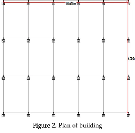
- The typical framing plan of G+9 storey
building is shown in figure the building is
rectangular
in
plan.
- Size of the building is taken as 15mX9m
- Each storey height is considered as 3m.
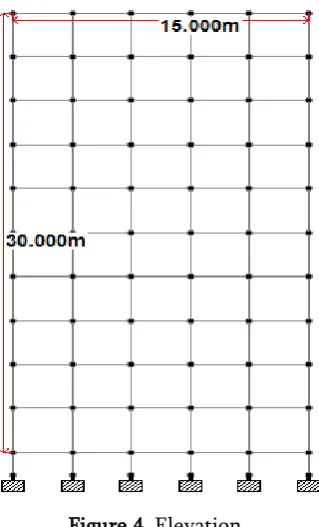
- Total Height of the building is 30m.
- Spacing of frame along length and width is 3m.
- Materials grade of M20 & Fe415 were used
for the design.
Figure 2. Plan of building
Figure 4. Elevation
Description of different Models
Model No.1 shows the model of regular building i.e. frame type.
Model No.2 shows the model of regular building with Rubber Base isolation provision.
Selection of factors
1) Zone II, Zone factor (Z) = 0.1 (As per IS 1893 (PART I):2002, Table 2)
2) I= Importance factor =1
3) (As per IS 1893 (PART I): 2002, 4) Table 6)
5) R= Response reduction factor 6) (for SMRF) = 5
7) (As per IS 1893 (PART I): 2002. 8) Table 7)
Table 1. Description of various elements
Discription Numeric value
Total depth of slab 150 mm
Floor finish load 1KN/m2
External wall thickness
230 mm
Internal wall thickness 230 mm
Size of external column
230 mm X 600 mm
Size of internal column
230 mm X 600 mm
Size of beam in longitudinal and transverse direction
230 mm X 400 mm
Live load 3KN/m2
IV. ANALYSIS AND RESULTS
Comparison of Shear force
Figure 5. Shear force in X direction
Table 2. Comparison of Shear force in X Direction at base
VX (Fix base) VX (Base isolated)
Figure 6. Shear force in Y direction
Table 3. Comparison of Shear force in Y Direction at base
VY (Fix base) VY (Base isolation)
271.70 KN 245.94 KN
A comparison of Shear force in X & Y direction is shown in the figure where you can see that the isolated frame has a less shear force while that of fixed base structure which has more shear force acting on the base of the structure.
If the shear at base is more then the lateral displacement of the structure will be more so to overcome the lateral displacements and to minimize the effect the rubber base isolating material is bolted between foundation and plinth level, so that all the lateral forces are taken by the Rubber and the superstructure is safe against the earthquake forces.
Comparison of Bending moment
Figure 7. Bending moment in X – direction
Table 4. Comparison of Bending moment in X direction at base
MX (Fix base) MX (Base isolated)
245992.28 KN-m 194274.01 KN-m
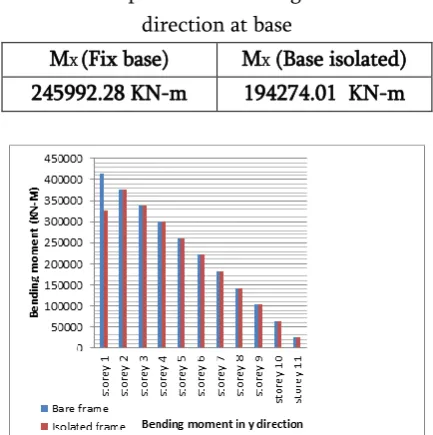
Figure 8. Bending moment in Y – direction
Table 5. Comparison of Bending moment in Y direction at base
MY (Fix base ) MY (Base isolated)
415266.00 KN-m 327958.00 KN-m
A comparison of bending moment in X & Y direction is shown in the figure where you can see that the isolated frame has a less bending moment while that of fixed base structure.
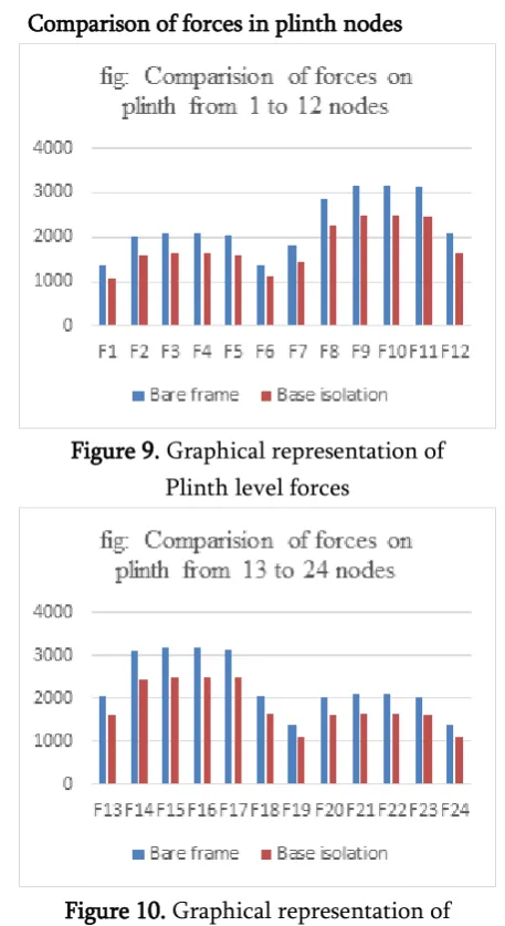
Comparison of forces in plinth nodes
Figure 9. Graphical representation of Plinth level forces
Figure 10. Graphical representation of Plinth level forces
IV.
CONCLUSIONS
Percentage reduction of shear force is found to be 10.70% by using base isolation.
Percentage reduction of Bending moment is found to be 21.02% by using base isolation.
It is found that the base isolation technique is very effective in the control of earthquake forces. Also this technique reduces shear as well as bending moment in the base storey which is our desired result. If the forces at the base is controlled, then it is
because the earthquake forces are transferred on the foundation through the soil, and then these forces are transferred on the superstructure through the foundation.
So, if the plinth level (base) of the building is safe against the collapse then the whole superstructure can be safe against the collapse, and plinth can only be safe if the forces coming through the earthquake can be reduced from its original magnitude.
So, the Base Isolation technique proves to be much efficient in the reduction of all kind of forces and also it protects the building from the collapse.
V.
REFERENCES
[1].Earthquake tips : IIT Kanpur
[2].IS 1893:2000 Indian code of practice for Earthquake resistant structure
[3].http://jclahr.com/science/earth_science/shake/ba se%20isolation/index.html
[4].Mazza F, Vulcano A. "Seismic response of buildings with isolation & supplemental dissipation at the base." Proceedings of the 5th World Congress on Joints, Bearings and Seismic Systems for Concrete Structures, Rome, Italy, 2001
[5].Sarvesh K. Jain and Shashi K. Thakkar 13th World Conference on Earthquake Engineering Vancouver, B.C., Canada August 1-6, 2004 Paper No. 1924
[6].
www.iitk.ac.in/nicee/IITK-GSDMA/EBB_001_30May2013.pdf