ISSN (Online): 2320-9364, ISSN (Print): 2320-9356
www.ijres.org Volume 3 Issue 8 ǁ August. 2015 ǁ PP.20-24
Multi resolution defect transformation of the crack under
different angles
Gao Kun
1, Chen Hao
2, Zhang Shengwei, Duan Yu, Zhang Wen-Ping
Correspondence should be addressed to Chen Hao
1(College of Automotive Engineering, Shanghai University Of Engineering Science, Shanghai 201620China) 2(College of Automotive Engineering, Shanghai University Of Engineering Science, Shanghai 201620China)
ABSTRACT :
It is used to analyze the crack of different angles by the method of finite element. In the
same material, the same crack is applied different angles, crack with 15 degree Angle differences, and
applying
Ⅰ
type load on the material. The effective elastic modulus under the different angles of
crack are obtained by finite element. With comparative judgment method, it provides the relationship
between the modulus of elasticity and crack different angles, and a method crack material defects of
transformation. On based on the transformation of energy equivalent principle, there are a lot of
crack defects of materials for different degrees of defects, so as to simplify the material crack, provide
a simple way for material fatigue analysis
.Keywords –
multiresolution;material defect;elasticity modulus
I.
INTRODUCTION
The most parts in mechanical engineering are under cyclic loading, so the cycle load is a major cause of leading to fatigue damage. In general, for high cyclic fatigue, Material of stress level is far less than the yield strength of its own and therefore fatigue damage of sudden, so often with huge property losses and casualties. There are two main types of research method of fatigue life, the kind of research method is based on damage mechanics and fracture mechanics; Another is to use s-n curve to predict the fatigue life. The former could not accurately the fatigue process of material defects, so the feasibility is poor; the latter need to do a lot of fatigue life test, wasting time and energy. The new method for fatigue life prediction of mainly on the material defects to simplify classification. For example, The GongL, Beijing University of Technology, on the labview platform is presented in this paper. a intelligent recognition system of defects, but the accuracy is not high; Xue-zhi Yang, hefei industrial university, China put forward a minimum classification error small potter of the textile defects classification research, but this method mainly is in textiles, limitations. At the university of Michigan, ShenJie, different defect levels of transformation method is put forward, Mainly for the approximation of the triangle, circle, square defects,, using the finite element simulation and numerical analysis method to the simplification of different levels of defects. However, no study of crack configuration of different angles, this paper mainly aims at this problem, the different point of view of limited analysis of crack, determine the crack under different angle of effective elastic modulus of the material.
II.
M
ULTIRESOTION MOTHEDS2.1The defect of multiresolution transformation
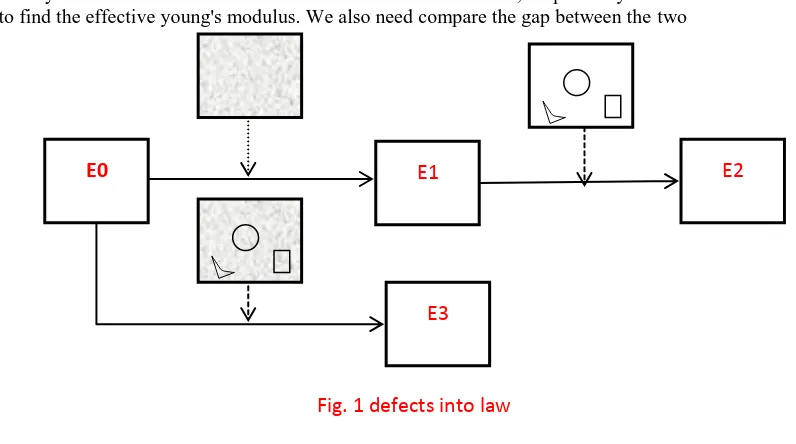
Eventually it is determined for the elastic modulus of E2 and E3, respectively under the two kinds of methods to find the effective young's modulus. We also need compare the gap between the two
2.2Numerical analysis of multi resolution
The above example is only two levels of the classification of the crack under simplified, whether classify can simplify between cracks, the heaviest is that if damage conversion is effective. The most crucial step is that a multi-scale damage mechanics model is set up. We assume that: the different levels of complementary energy of elastic mechanics modelis expressed by the following
𝑊𝑒 𝜎
𝐷𝑖, 𝐷𝑖 =12𝜎𝐷𝑇𝑖:𝐶 𝐷−1𝑖:𝜎𝐷𝑖,i = 0,1,,,n (1)
We()——a complementary elastic energy,
Di——a damagetensor that represents the extent of damage accumulated from level 1 to leveli,
T——the transpose of a matrix, σDi——a stresstensor at damageDi,
C D−1i——the inverse of an effective stiffnesstensor,
There is the following special case:in whichC−1is the inverse of a stiffness tensor at damage D0=0.C D−1i = C−1,(2)
We also assume that the equivalence of complementary energy takes thefollowing incremental form:
𝑊𝑒 𝜎
𝐷𝑖+1,𝐷𝑖+1 = 𝑊𝑒 𝜎𝐷𝑖+1,𝐷𝑖
=1
2𝜎 𝐷𝑇𝑖+1:𝐶 𝐷−1𝑖:𝜎 𝐷𝑖+1 =1
2𝜎 𝐷𝑇𝑖: 𝑀 𝑑𝐷𝑖 𝑇:𝐶 𝐷−1𝑖:M 𝑑𝐷𝑖 :𝜎 𝐷𝑖(3)
σDi+1——The effective stress tensor in the Di+1, To solve the equations as follows:
𝜎 𝐷𝑖+1= M 𝑑𝐷𝑖 :𝜎 𝐷𝑖,(4)
d𝐷𝑖 = 𝐷𝑖+1− 𝐷𝑖,i = 0,1,,n − 1(5)
The equation expressed the material defect ofmulti-resolution transformation rules. It is mainly used for the different levels material defects to be homogeneously processed.
III.
F
INITE ELEMENT ANALYSIS OF CRACK DEFECT DISCUSSION3.1Sample simulation parameters
The finite element software is used in the simulation of ABAQUS, and the stress singularity at the crack tip of ABAQUS has a strong analytical ability, which can show the crack propagation phenomenon. The specific parameters of the sample are shown in Table 1
E1
E2
E0
E3
Table 1 The simulation test specimen
Parameter Data
Specimen size(L×B) 100×40(mm)
Applying external force
(kPa) 100
Crack sizes (L) 10(mm)
Crack angle (degree) 15
Elasticity modulus 3×10⁷
Poisson ratio 0.3
3.2Analysis and calculation of elastic modulus in finite element method
This Due to the material itself inherent attributes, there are some inevitable defects on materials. In the machining process of parts, there are different length and arrangement of cracks. As shown in the following diagram: the crack is rotated counterclockwise, and the angle of each rotation is 15 degrees, and the straight line between the figures is preset. Boundary conditions: The sample boundary in the direction of Y axis is fixed, allowing the displacement in the X axis direction. The stress and strain are solved under different conditions. Due to the limitations of the finite element software, we can only get the stress or strain of a single node or element, so we need to solve the average stress and average strain of the whole material.
σ =F1+F2+⋯ A (6) ε = d1−d3 + d2−d4 +⋯
nL (7) σ:mean stress,
ε:mean strain, Fi:the force of node i, n:node number,
3.3Calculation results and discussion of elastic modulus
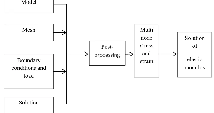
Finite element software can be on the structure of stress and strain analysis, using the finite element software general after pre-processing, solution and post treatment process by visualization module in the post processing of the extracted n nodes stress and displacement components, to approximately calculate the presence of different defects of the elastic modulus of materials. The specific analysis process as shown in Figure2
Fig. 2 Analysis of elastic modulus in finite element
method
ModelMesh
Solution Boundary conditions and
load
Post- processing
Multi node stress and strain
Solution of
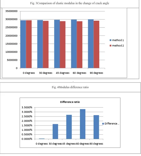
It in Figure 3shows values for the elastic modulus under different angles, wherein E1 represents a crack perpendicular to the external load, E2 load and crack angle is 15 degrees, and so on. From the table available, when cracks are present at different angles, the elastic modulus of gradual change. Perpendicular to the crack and the external load and change of its elastic modulus value maximum, the influence on the properties of materials maximum. With the increase of the angle, trend of elastic modulus decreases, finally tends to be stable, From Figure 4, the difference in elastic modulus is within the allowable range of 10%
Fig. 3Comparison of elastic modulus in the change of crack angle
.
Fig .4Modulus difference ratio
IV.
C
ONCLUSIONFor fatigue analysis, due to the irregularity of the crack, it is almost impossible to adopt accurate classification of crack. Finite element simulation through the cracks of different angle, we can summarize influence of edge crack of elastic modulus is greater than the median crack; influence of cracks on the elastic modulus is greater than a single crack; crack in different angles, elastic modulus with the change. The vertical
0 5000000 10000000 15000000 20000000 25000000 30000000 35000000
0 degrees 30 degrees 45 degrees 60 degrees 90 degrees
method 1
method 2
0.0000% 0.5000% 1.0000% 1.5000% 2.0000% 2.5000% 3.0000% 3.5000%
0 degrees 30 degrees 45 degrees 60 degrees 90 degrees
Difference ratio
effects of the elastic modulus of the material to a load ofthe crack. It has important significance for predicting fatigue life and the simplified finite element model,.
R
EFERENCES[1] Le bow, Cao Kang, Wu Miao. Metal materials in ultrasonic flaw detection of defect classification of auxiliary system of [J]. Chinese Journal of scientific instrument,2005,10:1085-1088.
[2] Mashayekhi M, Taghipour T, Askari A, Farzin M. Continuum damage mechanics application inlow-cycle thermal fatigue. International Journal of Damage Mechanics. 2013; 22(2):285-300.
[3] Zhang Haiyan, comprehensive, Xia Jindong. Wavelet packet noise reduction and feature extraction of ultrasonic defect echo signal [J].2006,01:94-97+105.
[4] Ke Chang Bo, Chen Tiequn. Development trend of [J]. physical testing of signal processing techniques in ultrasonic nondestructive testing of coarse grained materials,2006,05:37-41.
[5] ChangRuisheng wavelet theory. The friction welding defect detection and recognition based on [D]. of Northwestern Polytechnical University,2004.
[6] Gao, X., Wang, T. and Kim, J. (2005). On Ductile Fracture Initiation Toughness: Effect ofVoid Volume Fraction, Void Shape and Void Distribution, International Journal of Solidsand Structures, 42: 50975117.
[7] Lemaitre J, Chaboche JL . Mechanics of solid materials. Cambridge University Press:1990.
[8] Kwofie S, Rahbar N. A fatigue driving approach to damage and life prediction under variable amplitude loading. International Journal of Damage Mechanics. 2013; 22(3):393-404.