www.ijres.org Volume 7 Issue 2 Ser. I ǁ 2019 ǁ PP. 19-32
Loop Thermosyphon as One-Turn Annular Pulsating Heat Pipe
L. L. Vasiliev
*, M. I. Rabetsky, L. P. Grakovich, A. S. Zhuravlyov
Porous Media Laboratory, A .V. Luikov Heat and Mass Transfer Institute,National Academy of Sciences of Belarus, Minsk, Belarus
*Corresponding Author:L. L. Vasiliev
ABSTRACT:
This study is aimed at experimental evaluation of the evaporation and condensation heat transfer inside a novel design – one turn annular pulsating heat pipe assisted by loop thermosyphon (LTPE). The evaporator and condenser of LTPE are connected with each other by flexible minipipes to transfer liquid and vapor. A cylindrical evaporator of LTPE has a porous coating on its internal surface and the liquid transport minipipe positioned along the evaporator axis thus organizing an annular channel between the porous coating of the evaporator and the liquid pipe. The goal of this study is the determination of the thermal resistance of the evaporator and condenser and the temperature field along the LTPE. Experimental data on the heat transfer coefficients in boiling and evaporation on a flooded and a partially flooded horizontal tube of the evaporator were obtained. Mini porous coating on the heat loading wall of the evaporator ensures an increase of the heat transfer (2–2.5 times) in comparison with the boiling heat transfer of the smooth tube in the liquid pool. An LTPE guarantees a shortened start-up time, decreases the evaporator wall temperature, has a small temperature hysteresis during the increase/decrease of the heat load and suppresses the temperature pulsations inside the evaporator. An LTPE evaporator is made from a copper tube (d = 12 mm, inner diameter 8 mm) with the length 130 mm. The LTPE wick is made from sintered copper powder, the porous wick thickness is less than 1 mm. Working fluids R245fa and R600 were used. The thermal resistance of LTPE evaporator is 0.1–0.05 K/W.Keywords:
Pulsating heat pipe, loop thermosyphon, heat transfer, phase change, sintered powder
wick, thermal resistance, cooling system, heat sink.
--- --- Date of Submission: 22-06-2019 Date of acceptance:08-07-2019 ---
---I.
INTRODUCTION
Two phase heat transfer devices (heat pipes and thermosyphons) are interesting for their compactness, high performance and possibility of being completely thermally driven (passive). The increasing need of managing high heat fluxes, either to be dissipated (electronics cooling) or to be recovered (solar concentrators), drives toward the design of more efficient and reliable devices. A modern trend in MEMS microelectronic and optoelectronic devices is the increase of the level of integration by minimizing the device size (high density packaging) and increase of the device performance (higher frequency). Two-phase thermal control systems such as loop heat pipes (LHP), loop thermosyphons (LT), mechanically pumped two-phase loops (MPL), and evaporative spray cooling (ESC), pulsating heat pipes play a vital role in heat dissipation and recently have been widely used in the electronic components cooling and some other energy applications [1–5]. The capability to transport heat at high rates over appreciable distances, without any requirement for external pumping devices, the low cost, durability and relatively simpler modeling/design process make this technology very attractive for many thermal management applications. Since there is a strong demand in miniaturization in commercial applications, the emphasis is placed on reducing the physical size during the design stage of new systems. Two-phase loop thermosyphons and pulsating heat pipes are one of convenient systems for such electronic components cooling [5–7].
Some designs of loop thermosyphons and pulsating heat pipes have been proposed to overcome the flooding limit, which include an internal physical barrier along the adiabatic section by-pass line for liquid return, a cross-over flow separator. The main advantage of these designs is that the liquid and vapor flows have partially separated passages, which can result in a higher flooding limited heat transfer capacity. Recently polymer loop thermosyphons with a flat interface (for attaching heat generated elements) were suggested and tested in [8]. The evaporator and condenser of this thermosyphon have the form of slabs located horizontally. They are connected by flexible polymer pipes used for transmission of vapor and liquid streams.
serpentine (3-mm internal diameter, filled with FC-72). The influence of the inclination angle and evaporator wettability on heat performance of the thermosyphon was studied in [7] by both numerically and experimentally.
Cryogenic loop heat pipes are of great interest for cooling and thermal regulation at low temperatures (some medical and infrared sensors, superconductive magnetic materials) [9, 10]. Low temperature medical probe based on a heat pipe application for hypothermia human local cavity was suggested and tested in [11]. Heat transfer in heat pipes and thermosyphons using different technologies including nanofluids, nanocoatings, and nanocomposites are analyzed in detail in some publications [12–16]. Modern loop heat pipes for the electronic components cooling with sophisticated types of porous membrane were designed and tested in [17– 22]. Three types of evaporators were fabricated to integrate with other LHP components, such as microchannels wick evaporator (MWE), modulated monoporous wick evaporator (MME), and modulated biporous wick evaporator (MBE) that were used in these experimental program. Different types of thermosyphons have been investigated in plenty of fields such as nuclear reactors [23, 24], energy systems [25], solar heat recovery [26–28], air conditioning [29], electronics cooling in avionics [30].
The devices mentioned effectively work under optimal conditions. For thermosyphons this is a vertical or close to vertical position, heat pipes are less sensitive to orientation in space, but their heat transfer capacity drops at low hydrostatic pressures. Meanwhile, in some cases, when solving problems of heat removal, it is necessary to locate the evaporator and condenser horizontally, while from the layout conditions they should be quite long. Loop heat pipes [31] are capable of transferring heat flow in a horizontal direction and even in a direction opposite to the gravity vector, however, LHP has limitations on the length of the evaporator, and there may be some problems with starting, such as a long start-up time or thermal and hydraulic oscillations at low heat loads. The specified reasons were the motivation for the development and study of a new design of thermosyphon.
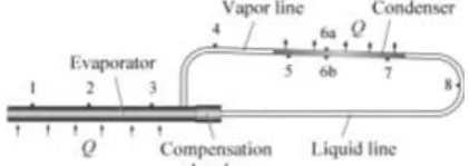
This study is oriented on the tests of the loop thermosyphon with porous coating of the evaporator. The simplest LTPE consists of an evaporator, condenser, a compensation chamber, and vapor and liquid pipes, Figure 1. The suggested concept is to use a new combined two-phase pumping mode of the working fluid inside the annular minichannel of the evaporator. A new loop thermosyphon with porous evaporator is suggested for electronics cooling, medicine as a “cold finger” to cool human body, solar photovoltaic and hot water systems due to its unique features such as high thermal conductivity, long, thin, and flexible evaporator.
II.
DESIGN OF LTPE WITH HORIZONTAL POROUS EVAPORATOR
The goal of this work is to study an original loop thermosyphon as annular one-turn pulsating heat pipe having horizontal cylindrical capillary coated evaporator (LTPE) with the length 130 mm, diameter 12 mm, a liquid cooled cylindrical condenser, compensation chamber, and vapor and liquid pipes between the evaporator and condenser. A sintered copper powder porous wick (of about 1 mm thick) is placed inside the evaporator. The condenser is made as a 105-mm-long straight copper tube, 6 mm in diameter placed inside the liquid/liquid heat exchanger. The compensation chamber is used to ensure the successful start up of LTPE, supply the end part of the wick by working fluid with the help of a capillary suction and accumulate the non-condensible gases, if they are generated inside LTPE.The total length of LTPE including vapor and liquid lines is about 500 mm. The heat receiving element is the evaporator. The heat absorbed in the evaporator during two-phase heat transfer is transported by the vapor flow from the evaporator to condenser through the vapor pipe. The heat flow is released during vapor condensation inside the condenser. Under the action of gravity forces LTPE ensures transport of liquid from the condenser to the evaporator and of vapor from the evaporator to condenser through the liquid and vapor thin pipes (d = 4 mm and 3 mm). The compensation chamber inside the evaporator contains a certain volume of the working fluid even when the condenser and liquid pipe are completely filled with the liquid. The LTPE is thus a reliable self priming system.
Figure 1: LTPE with cylindrical horizontally placed evaporator, compensation chamber, and condenser. Points 1–8 indicate thermocouples positioned on the thermosyphon surface.
∆Pg +∆Pbg ≥ ∆Pl +∆Pv +∆Pe +∆Pc, (1)
where ∆Pg is the gravitational pressure drop; ∆Pbg is the pulsating pressure drop due to the bubble generation in the annular channel; ∆Pl is the pressure drop of the liquid flow; ∆Pv is the pressure drop of the vapor flow, and ∆Pe and ∆Pc are the pressure drop due to evaporation and condensation at the liquid-vapor interface, respectively. To ensure LTPE functioning properly, the sum ∆Pg+ ∆Pbg ought to be larger or at least equal to the sum of all the pressure losses mentioned above. There is also capillary pressure drop ∆Pcap along the porous coating perimeter; ∆Pcap is responsible for the liquid capillary suction inside the porous coating from the liquid rivulet inside the annular channel.
, l l
cap gH
d dH K
H
P
(2)
where l is the dynamic viscosity of working liquid; H is the height capillary rise; l is the density of working liquid; K is the permeability of porous wick; is the time.
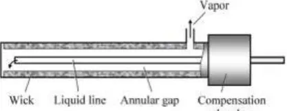
The evaporator of LTPE with porous wick is the most important component of this device. The LTPE wick is made of sintered copper powder; the wick parameters are carefully examined and tested before the final decision was made which type of porous structure is the best. This evaporator has the annular channel between a small pipe for liquid transport and a porous wick inside the evaporator, Figure 2.
Figure 2:Longitudinal section of the LTPE evaporator.
The porous structure, the working mechanism, and the test conditions actually are described for better understanding the visualization. The porous coating within an evaporator has the following functions: heat conduction through wick, vapor generation and release within macropores, and liquid supply due to the capillary force with mesa- and micropores. These functions are affected by such parameters as particle size, porosity, permeability, wick layer thickness, etc. Two-phase fluid flow with boiling, evaporation, and capillary sucking along the porous structure takes place in an annular minichannel of the evaporator. The end of liquid pipe of the condenser enters the LTPE evaporator, organizing an annular minichannel between the pipe and the porous coating of the evaporator. The intense two-phase heat and mass transfer inside the annular minichannel of the evaporator is available due to boiling of working fluid in the channel and evaporation of it inside the porous material. Evaporation in the volume of the porous wick takes place under the heat load application. There is a combined action of pressure difference along the annular gap due to the gravity forces, liquid bubble generation in the channel, and action of capillary forces along the perimeter of porous wick.
III.
EXPERIMENTAL SETUP FOR SINTERED COPPER POWDER MATERIALS
ANALYSIS
AND DESIGN
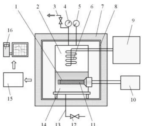
Figure 3:Experimental setup: 1) annular minichannel, 2) stainless steel vessel with the liquid pool, 3) exhaust system for noncondensable gases, 4) manometer, 5) vacuum meter, 6) condenser, 7) hermetic thermal controlled chamber, 8) liquid loop for temperature regulation of the guard thermal
screen, 9) cooling machine, 10) power supply, 11) cartridge heater, 12) valve, 13) liquid feeding system, 14) liquid pool, 15) data acquisition system, 16) computer.
Propane (R290) was chosen as the modeling working fluid due to its good thermodynamic properties, low cost, availability, compatibility with constructional materials, and environmental friendship.
In our experiments, the sample (horizontal cylinder) with a diameter of 20 mm was placed inside the transparent glass tube with annular minichannel 0.8–1.8 mm (Figure 4). The size of annular channel was close to the capillary constant
12v l
2 g
. (3)
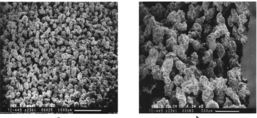
Different SEM images of sintered copper particles coating (porosity ~50%, particle diameter 63–100
m, mean particle diameter 82 m, mean pore hydraulic diameter 24.5 m) on the copper tube are shown in Figure 5.
Figure 4:The cross-section of the tested sample partially flooded (left) and put in the liquid pool (right): 1) liquid surface, 2) test sample, 3) glass tube, 4) electrical heater, H is the height of liquid level.
placed in a liquid pool, we have the closed-type micro heat pipe phenomenon. For partially flooded sample we have the open-type micro heat pipe phenomenon.
a b
Figure 5: SEM images of sintered copper powder structure (a) and (b) with different pore sizes.
A porous structure interacts with the bubble-induced liquid flow in the annular minichannel and assists in bubble generation. A displacement of hot liquid by growing bubbles occurs in the minichannel. The minimum wall and porous coating superheat is required following the thermodynamics for stable vapor bubbles on the macropores outlet. Microscale effect is related to the micro heat pipe phenomena inside the porous structure. Miniscale effect is influenced by the annular minichannel geometry. The minimum wall and porous coating superheat is required following the thermodynamics for stable vapor bubbles on the macropores outlet. Microscale effect is related to the micro heat pipe phenomena inside the porous structure. Miniscale effect is influenced by the annular minichannel geometry. Experimental results show, that such channel geometry is favorable for the heat transfer enhancement. A heat transfer surface in such a two-phase heat transfer system is considered to be near ideal, because the variation of the heat flux does not result in any change of the driving temperature difference, the bubble density increases with rising heat flux.
All experimental data were obtained under steady-state working conditions. The heat transfer coefficient was calculated as
T
wT
l
q
T
q
h
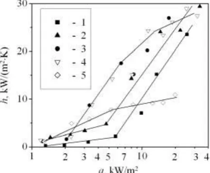
. (4)Visual observation of two-phase heat transfer testifies that vapor bubbles movement in circular minichannel has a complex character. Bubbles can be considered as the micropumps to move vapor and liquid not only perpendicularly to the surface of heat releasing component but also to ensure the swing two-phase flow along a tube axis from the input (bottom) toward the outlet (upper part) of the glass tube before entering the liquid pool. The heat transfer coefficient was found to be dependent on a liquid/vapor interface position inside the glass tube: it was the highest, when the interface position inside the glass tube was accompanied by partial flooding of the sample. In the circular minichannel forced convection of the two-phase flow takes place without additional power supply (no mechanical pumping) due to the vapor generation in the macropores, accompanied by liquid flow additional turbulence. The fluid in the upper central part of the glass tube takes the form of slugs due to the low fluid velocity and small cross section of the minichannel. The volume expansion due to vaporization causes an oscillating motion of the fluid to the liquid volume with vapor plugs and liquid slugs. At low and moderate heat fluxes (q < 100 kW/m2) micro heat pipe effect is available in the pores accompanied with two-phase forced convection in the annular minichannel (porous sample inside the glass tube). The availability of annular minichannel significantly promotes to intensification of heat transfer (2.5–3 times) to compare with liquid pool. The data obtained on flooded (H = 70 and 20 mm) and partially flooded (H = 15, 10 and 5 mm) porous cylinder are shown in Figure 6.
coefficient was available when a liquid interface was by a quarter of the sample diameter (H = 15 mm) to compare with completely flooded sample (Figure 4).
Lowering the value of H down to 10 mm (interface is at the middle of tube diameter) decreases the heat transfer intensity at heat flux q > 15–20 kW/m2, due to the insufficient liquid suction to the meniscus of evaporation.
Figure 6:Heat transfer of porous wick placed in the liquid pool and in the annular mini channel with different H height: 1) liquid pool, 2–5) annular minichannel, H = 75, 20, 15, and 10 mm respectively.
There are two limitations for heat transfer intensity in such porous body: hydrodynamic ability of porous coating to transport liquid and a finite number of vaporization centers (curvilinear menisci in the orifices of micropores). The heat transfer intensity depends on the curvature km ax of menisci. While the curvature k
does not exceed some value of km ax, the capillary suction of liquid is good. On reaching a certain value of heat
flux Qmax, menisci move inside micropores, the meniscus curvature k increases and exceeds km ax. When the
meniscus curvature increases to k km ax, the drainage of heated surface begins. Consequently, a heat exchange surface disposed above the liquid interface does not get sufficient amount of liquid. “Dry spots” appear and spread over the entire surface. The liquid interface becomes lower; the heat transfer coefficient is decreasing.
IV.
EXPERIMENTAL TESTING OF LTPE PARAMETERS USING DIFFERENT
WORKING FLUIDS
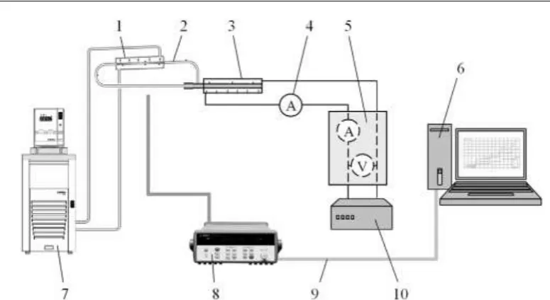
To determine the heat transfer capacity of the LTPE, a series of experiments were conducted using different working fluids. The scheme of the experimental setup is shown in Figure 7.
An electric heater was applied as a source of energy. Heat flow was absorbed by the water cooling system. The liquid temperature inside the Circulating Thermostatic Bath Carbolite Gero Limited, Julabo FP-89 was changing from the “cold” to “hot” temperature (20 to 80C) and has a liquid flow rate of 10 L/min. The precision of the liquid temperature maintenance in the Bath is ±0.1С. The temperature of the cooling liquid was recorded by the Agilent 34970A data acquisition system. The working vapor pressure inside the LTPE during the test was measured using a PSA-C01pressure sensor, and the NI-9203. The precision of the heat flow measurements was ±5%. To analyze the thermal performance of the LTPE properly, the system had been perfectly thermo insulated to prevent heat loss to the surrounding environment. LTPE samples were tested using two working fluids, R245fa and R600. In these experiments, the heat load starting from 10 W was increased up to 30, 40, 50, 60, 70, 80, 90, 100, and 120 W and then was decreased back. The temperature field along the LTPE was registered by thermocouples placed on the surface of evaporator and condenser, Figure 1.
Figure 7: Scheme of the experimental set-up for LTPE testing: 1) liquid flow heat exchanger, 2) LTPE, 3) electrical heater, 4) ammeter, 5) wattmeter, 6) computer, 7) thermostat, 8) Agilent for data
acquisition/logger for data registration, 9) signal cable for thermocouples, 10) regulated power supply.
It is of importance that this performance was achieved without the need to actively adjust or control the flows in the system, even when the heat inputs varied between 0 and 3.5 W/cm2.
Evaporation and condensation heat transfer inside such LTPE was evaluated and experimentally validated. LTPE thermal resistance, temperature field along the evaporator and condenser for different heat loads with uniformly heated evaporator surface were tested and analyzed.
The hydrodynamics of the working fluid and heat transfer along the evaporator can be divided into four zones with various modes of heat and mass transfer mechanism, Figure 8. Such regimes were also observed when studying heat transfer processes in the annular channel between the heated porous sample and the glass cylinder at different depths of immersion in the liquid pool, Figure 9:
1) subcooled liquid flow pre-heating zone (Figure 9 a); 2) transient zone of liquid boiling, Figure 9 b;
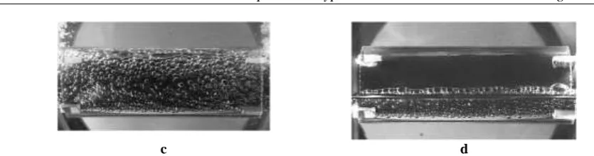
3) zone of developed liquid boiling (Figure 9 c);
4) zone of liquid evaporation inside the porous wick (Figure 9 d).
Figure 8:Zones of hydrodynamic and heat transfer along the evaporator.
Thin sintered copper powder structure with micro heat pipe phenomena simulates the increase in evaporative heat transfer by about 8–10 times to compare with propane pool boiling heat transfer on the smooth horizontal tube. Reducing the size of cooling system we increase its efficiency, improve system performance by adding microscale function (micro heat pipe effect) to macroscale engineering application.
c d
Figure 9:Modes of heat transfer in the evaporator: a) subcooled liquid heating near the entrance of the annular minichannel of LTCE evaporator; b) beginning of nucleate boiling of the saturated liquid in the
annular minichannel of LTCE evaporator; c) bubble flow heat transfer;
d) evaporation inside the wick, capillary suction of the liquid from the liquid rivulet at the bottom of evaporator.
The average temperature difference, ∆Tavg, Eq. (5), between the evaporator and condenser is found by subtracting the average condenser temperature, Tc [Eq. (6)], from average evaporator temperature, Te, Eq. (7). There is a capillary suction of the liquid by the annular porous wick with intense liquid evaporation inside zone 4. This mode of heat transfer is the most intense and efficient.
∆Tavg = Te – Tc, (5)
3 3 2 1 e
T T T
T , (6)
3 7 6 5 ñ
T T T
T , (7)
where T1, T2, T3 and T5, T6, T7 are the temperatures occurring at the respective thermocouples locations on the evaporator and condenser, Fig. 1. The heat transfer intensity along the LTPE evaporator depends on the heat flow (rate of liquid flow from the condenser to the evaporator) and the porous structure parameters of the wick, Figure 10.
4.1 TEST RESULTS OF THE LTPE #1, COPPER-R245FA
The geometric parameters of the LTPE, sample #1, copper-R245fa, are presented in Table 1.
Table 1: Dimensions of the LTPE components (sample #1).
Characteristic Size, mm
Length of the evaporator 130
Diameter/wall thickness of the evaporator 12/1
Length of the condenser 105
Diameter/wall thickness of the condenser 4/0.5
Length of the vapor line 90
Diameter/wall thickness of the vapor line 4/0.5
Length of the liquid line 350
Diameter/wall thickness of the liquid line 3/0.5
Temperature evolution of LTPE #1 for different heat loads Q is shown in Figures 11 and 12. The temperatures of the evaporator, condenser, working fluid, heat sink (thermostat), and of the cooling liquid coming in and out from the heat exchanger were measured. The obtained results of temperature measurements testify that LTPE, copper-R245fa, has a good dynamics of start-up. The LTPE heating starts reliably at sufficiently low heat loads (less than 10 W). LTPE is stable in operation over a wide range of heat flows (10– 100 W). The total thermal resistance Rt of LTPE copper-R245fa, does not exceed 0.5 K/W (for evaporator Re = 0.1–0.05 K/W) in the heat load range 30–100 W.
Figure 11: Start-up of LTPE, sample #1. Te, Tv, Tc, and Tl are the temperatures of evaporator, vapor, condenser, and liquid respectively. Working fluid – R245fa.
The experimental data testify that the temperature difference along the evaporator is small, Figure 12. Thermal resistance of the evaporator and condenser and the total thermal resistance of LTPE as a function of temperature of the cooling bath are shown on Figures 13 and 14. The dependence of thermal resistance of LTPE on the temperature of the cooling water was analyzed at the heat load Q = 40 W. The thermal resistance of LTPE condenser Rc and the total thermal resistance of LTPE increase with the heat load. It should be noted that with increase of the temperature of the cooling liquid in the circulating thermostatic bath the total thermal resistance of LTPE decreases, Figure 14. This is very important, since when providing thermal conditions for the electronic equipment disposed in a hermetic volume saturated with the electronic components, it is not possible to cool the condenser of a thermosyphon with the cold air or use the additional liquid cooling system. The experimental data testify that the temperature difference along the evaporator is small.
Figure 13:Thermal resistances of evaporator Re and condenser Rc and the total thermal resistance Rt of LTPE #1 as a function of the LTPE heat load.
Figure 14: Thermal resistances of evaporator Re, condenser Rc, and the total thermal resistance Rt of LTPE #1 as a function of the temperature of the cooling water, Q = 40 W.
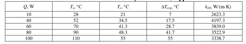
The effective thermal conductivity, keff, of LTPE was calculated by
avg eff eff
T A
QL k
, (8)
where Q is the heat load and A is the cross-sectional area of the LTPE evaporator. The experimental data of keff
typical of LTPE #1, copper-R245fa, are shown in Table 2.
Table 2: Effective thermal conductivity of LTCE #1, copper-R245fa
Q, W Te, C Tc, C ∆Tavg, C keff, W/(mK)
10 28 21 7 2623.3
40 52 34.5 17.5 4197.3
60 70 41.3 28.7 3839.0
80 90 48.3 41.7 3522.9
100 110 55 55 3338.7
4.2 THE TEST RESULTS OF LTPE #2, COPPER-R600
Figures 15 and 16. The temperature curves are presented for such LTPE components as evaporator and condenser, phases of working fluids in the vapor and liquid lines, heat sink, and the working liquid coming out from the condenser.
Figure 15: Temperature distribution along LTPE (sample #2) as a function of time and heat load in the evaporator. Working fluid is R600. Te, Tv, Tc, and Tl is a temperature evolution of the evaporator, vapor,
condenser, and liquid, respectively.
Figure 16:Temperature profiles along LTPE (sample #2) as a function of heat load in the evaporator. Working fluid is R600.
The thermophysical parameters of LTPE #2 are similar to LTPE #1. Thermal resistances of the evaporator, condenser, and total thermal resistance of LTPE as a function of temperature of the cooling liquid in the thermostatic bath are shown in Figures 17 and 18, depending on the heat load of LTPE. It should be noted that with increase of the temperature of the cooling liquid the thermal resistance of LTPE decreases due to the decrease of the working fluid overheating. The temperature value of the LTPE (sample #2) evaporator is higher that the temperature of the LTPE (sample #1).
Figure 18.Thermal resistances of evaporator Re and condenser Rc and the total thermal resistance Rt of LTPE #2 as a function of temperature of the cooling bath at Q = 40 W.
4.3 CONDENSER OF LTPE DEVICE
The condenser/radiator used in this experimental program is the component with the high mass and surface area. The rate of the fluid accumulation in the condenser depends on several factors and processes such as:
condenser temperature;
heat load;
temperature and pressure in the evaporator;
working fluid thermophysical properties;
back conduction;
conditions of the vapor breaking through the condenser into the evaporator;
vapor breaking through the condenser into the evaporator;
liquid subcooling coming to the evaporator from condenser due to changes in the radiator temperature.
The ability to use a “hot” cooling liquid in LTPE has an important prospect for its application in cooling systems of data-centers. The cooling capacity of LTPE condenser is calculated from the following expression:
Qout = mcp(Tout – Tin), (9)
where m, cp, Tout and Tin are the liquid flow rate, specific heat at the constant pressure, outlet temperature, and inlet temperature of chilled water, respectively;
Rt = ∆T/Q = (Te – Tc)/Qactual, (10)
where Te and Tc are the average temperature of the evaporator and condenser, Qactual is equal to the mean value of the heat removal from the condenser and supplied power to the evaporator Qin.
Many data such as optimal geometric parameters of LTPE, liquid filling ratio of the evaporator, heat load, tilt angle, and the start-up time, were used in the experiments.
The thermal resistance of the evaporator Re, condenser Rc, and the total thermal resistance Rt of LTPE are calculated by following the formulas:
Re = (Тe–Тv)/Q,
Rc= (Тv–Тc)/Q, (11) Rt = (Тe –Тc)/Q.
One of the outstanding features of LTPE is its long distance transportation ability of a high heat load with small temperature drop. LTPE with the evaporator up to 200 mm in length and 10–12 mm diameter can maintain the temperature of a cooled object (heat generator) at a temperature below 80 С even at the heat loads from 100 to 200 W. This device ensures a short start-up time, decrease in the evaporator wall temperature, and suppression of the temperature instability inside the thermosyphon.
0.35–0.5 K/W (with evaporator Re = 0.1–0.05 K/W) in the heat load range 30–100 W. According to the data of [9], a start-up at low heat loads is problematic for conventional LHPs and loop thermosyphons. This problem is absent for LTPE. The porous coating of LTPE evaporator minimizes the temperature, pressure fluctuations, and noise. The application of porous coating in LTPE evaporator increases two-phase heat transfer intensity 2–3 times to compare with the pool boiling heat transfer of the loop thermosyphon with smooth wall of the evaporator.
V.
CONCLUSION
A reliable high-performance LTPE device was designed and tested for electronic components cooling. LTPE include the advantages of conventional heat pipes, loop heat pipes, and loop thermosyphons. The experimental results show that a modified system of LTPE is able to prevent dry-out phenomena of the working fluid in the evaporator up to heat load of 120 W. The porous medium helps spreading the liquid and heat uniformly along and across the evaporator. Test results showed that LTPE thermal resistance slightly decreases with the rise of heating power due to the rise of circulating fluid speed. Because of the passive capillary phase separation, the hybrid LTPE operation did not require any active flow control, even at highly transient and asymmetrical heat inputs along the evaporator. This device has good dynamics of quick reaching the operating mode; it starts at sufficiently low heat loads (less than 10 W) and is stable in operation over a wide range of heat flows. In this case, thermal resistance of the LTPE evaporator is 0.05–0.1 K/W for both tested fluids. The heat flow density for LTPE #2 (L = 120 mm) is equal to q = 48 kW/m2. At a heat load of 100 W, the surface temperature of the LTPE evaporator is 105C for R245fa and of about 100C for R600. Visualization of the micro heat pipe effect inside the porous structure two-phase forced convection in the annular minichannel testifies the availability of thermodynamically efficient mechanism of the semiconductor component cooling system, space thermal control, aircraft devices, traction drives and audio amplifiers.
VI.
NOMENCLSTURE
H – depth, height [m], h – heat transfer coefficient [W/(m2K)], K – permeability [m2], k – thermal conductivity
[W/(mK)], k – curvature [m], m – mass [kg], P – pressure [Pa], Q – heat flow [W], q – heat flux [W/m2], R – thermal resistance [K/W], T – temperature [°C].
Greek letters: – capillary constant [m], l – dynamic viscosity [m2/s], – contact angle [grad], – density [kg/m3], – surface tension [N/m], – time [s].
Subscripts: avg – average, bg – bubble generation, c – condenser, cap – capillary, e – evaporator, eff – effective, g – gravitation, l – liquid, t – total, v – vapor, w – wall, 0 – cooling agent, ambient environment.
REFERENCES
[1]. Garner S., Patel C. (2001) “Loop thermosyphons and their applications to high density electronics cooling” Proc. of IPACK'01, The Pacific Rim/ASME Int. Electron. Packag. Tech. Conf. and Exhib., Kauai, Hawaii, USA. IPACK2001-15782.
[2]. Singh R., Akbarzadeh A., Mochizuki M. (2008) “Operational characteristics of a miniature loop heat pipe with flat evaporator” Int. J. Therm. Sci. Vol. 47 Pp. 1504–1515. https://doi.org/10.1016/j.ijthermalsci.2007.12.013.
[3]. Ranasamy N. S., Kumar P., Wangaskar B., Khandekar S., Maydanik Y. F. (2018) “Miniature ammonia loop heat pipe for terrestrial applications: Experiments and modeling” Int. J. Therm. Sci. Vol. 124 Pp. 263–278. https://doi.org/10.1016/j.ijthermalsci.2017.10.018. [4]. Khrustalev D. (2002) “Loop thermosyphons for cooling of electronics” Proc. of 18th SEMI-THERM Symp., San Diego, Calif.,
USA. Pp. 145–150.
[5]. Winter M., Stephan P. (2012) “Evaporation from micro-porous surfaces in mechanically pumped two-phase loop” Proc. of 16th Int.
Heat Pipe Conf. (16th IHPC), Lyon, Fr. Pp. 295–300.
[6]. Mamelli M., Mangini D., Vanoli G. F. , Araneo L., Filippeschi S., Marengo M. (2015) “Multi-evaporator closed loop thermosyphon” 7th Eur.-Jpn. Two-Phase Flow Group Meet., Zermatt, Switz. Pp. 1–12.
[7]. Zhi Hu, Yaning Zhang, Bingxi Li, Chi-Chuan Wang, Yongji Li (2018) “The influence of the inclination angle and an evaporator wettability on the heat performance of the thermosyphon by simulation and experiment” Int. J. Heat Mass Transf. Vol. 116 Pp. 675– 684.
[8]. Vasiliev L. L., Grakovich L. P., Rabetsky M. I., Vassiliev L. L., Jr. (2013) “Heat transfer enhancement in heat pipes and thermosyphons using nanotechnologies (nanofluids, nanocoating, and nanocomposites) as an HP envelope” Heat Pipe Sci. Technol. An Int. J. No. 4 Pp. 251–275.
[9]. Zhao Y., Yan T., Liang J. (2011) “Experimental study on a cryogenic loop heat pipe with high heat capacity” Int. J. Heat Mass Transf. Vol. 54 Pp 3304–3308.
[10]. Khrustalev D. (2003) “Cryogenic loop heat pipes as flexible thermal links for cryocoolers” in: R. G. Ross, Jr. (Ed.), Cryocoolers 12, Kluwer Acad./Plenum Publ., pp. 709–716; 12:709-16, https://doi:10,1007/0-306-47919-2_93.
[11]. Vasiliev L. L., Zhuravlyov A. S., Molodkin F. F., Khrolenok V. V., Zhdanov V. L., Vasil'ev V. L., Adamov S. I., Tulin A. A. (1996) “Medical instrument based on a heat pipe for local cavity hypothermia” J.Eng. Phys. Thermophys. Vol. 69 Pp. 302–304. [12]. Vasiliev L. L., Vassiliev L. L., Jr., Zhuravlyov A. S., Shapovalov A. V., Rodin A. V. (2015) “Vapordynamic thermosyphon – heat
transfer two-phase device for wide application” Arch. Thermodyn. Vol. 36 Pp. 65–76.
www.ijres.org 32 | Page [14]. Mochizuki M., Nguyen Thang, Mashiko M., Saito Y., Nguyen Tien, Wuttijumnong V. (2011) “A review of heat pipe application
including new opportunities, Front. Heat Pipes” No. 2, 013001 Pp. 1–15. https://dx.doi.org/10.5098/fhp.v2.1.3001.
[15]. L. Winston Zhang (2006) An experimental study on applying miniature loop heat pipes for laptop PC cooling technol., Novark Technol. Inc. www.novark.com.cn (accessed febr. 2016).
[16]. Zhao Y., Yan T., Liang J. (2011) “Experimental study on a cryogenic loop heat pipe with high heat capacity” Int. J. Heat Mass Transf. Vol. 54 Pp. 3304–3308.
[17]. Hwang G. S., Park C. W., Kaviany M. (2015) “High-heat-flux distributed capillary-artery evaporators” in: K. Vafai (Ed.), Handb. of Porous Media, Third ed., Taylor and Francis, CRC Press, pp. 597–630.
[18]. Jinliang Xu, Xianbing Ji, Woiong Yang, Zwei (2014) “Modulated porous wick evaporator for loop heat pipes: Experiment” Int. J. Heat Mass Transf. Vol. 72 Pp. 163–176.
[19]. Vasiliev L., Zhuravlyov A., Shapovalov A., Litvinenko V. (2004) “Vaporization heat transfer in porous wicks of evaporators” Arch. Thermodyn. Vol. 25 Pp. 47–59.
[20]. Vasiliev L., Zhuravlyov A., Shapovalov A. (2012) “Heat transfer enhancement in mini channels with micro/nano particles deposited on a heat-loaded wall” J. Enhanc. Heat Transf. Vol. 19 Pp. 13–24.
[21]. Zhi Hu, Yaning Zhang, Bingxi Li, Chi-Chuan Wang, Yongji Li (2018) “The influence of the inclination angle and an evaporator wettability on the heat performance of the thermosyphon by simulation and experiment” Int. J. Heat Mass Transf. Vol. 116 Pp. 675–684.
[22]. Lahey R. T., Jr., Moody F. J. (1996) Thermal Hydraulic of Boiling Water Nuclear Reactor, second ed., Am. Nucl. Soc.
[23]. Sviridenko I. I., Shevielov D. V. (2011) “Autonomous thermosyphon system for WWER cooldown” Heat Pipe Sci. Technol. An Int. J. No. 2 Pp. 145–159. https://DOI: 10.1615/HeatPipeScieTech.v2.i1-4.150.
[24]. Franco A., Filippeschi S. (2013) “Experimental analysis of closed loop two phase thermosyphon (CLTPT) for energy systems” Exp. Therm. Fluid Sci. Vol. 51 Pp. 302–311.
[25]. Esen M., Esen H. (2005) “Experimental investigation of a two-phase closed thermosyphon solar water heater” Sol. Energy Vol. 79 Pp. 459–468.
[26]. Li J., Lin F., Niu G. (2014) “An insert-type two-phase closed loop thermosyphon for split-type solar water heaters” Appl. Therm. Eng. Vol. 70 Pp. 441–450.
[27]. Moradgholi M., Nowee S. M., Abrishamchi I. (2014) “Application of heat pipe in an experimental investigation on a novel photovoltaic/thermal (PV/T) system” Sol. Energy Vol. 107 Pp. 82–88.
[28]. Han L., Shi W., Wang B., Zhang P., Li X. (2013) “Development of an integrated air conditioner with thermosyphon and the application in mobile phone base station” Int. J. Refrig. Vol. 36 Pp. 58–69.
[29]. Sarno C., Tantolin C., Hodot R., Maydanik Yu., Vershinin S. (2013) “Loop thermosyphon thermal management of the avionics of an in-flight entertainment system” Appl. Therm. Eng. Vol. 51 Pp. 764–769.
[30]. Perpiña X., Pitón M., Mermet-Guyennet M., Jordà X., Millán J. (2007) “Local thermal cycles determination in thermosyphon-cooled traction IGBT modules reproducing mission profiles” Microelectron. Reliab. Vol. 47 Pp. 1701–1706.
[31]. Khrustalev D., Cologer P. (2010) “Transient modeling of hybrid loop heat pipe systems with multiple evaporators” Front. Heat Pipes. 1 013002 1–1. DOI: 10.5098/fhp.v1.1.3002.