11
Vibro-Dynamic Approach Of The Platform And
The Interface Of The Railways Ballast.
G. Tchemou, P. W. Huisken Mejouyo
Laboratory of Mechanics (LM), University of Douala;
Laboratory of Mechanics and Appropriate Materials (LAMMA), University of Douala;
Abstract: This study highlights the importance of the geotechnical characteristics of the platform taking into consideration the vibratory combination of systems which tend to support the separation of the particles. Considering the diffusion of the pressure in the ballast, it has been divided into three zones: ballast without overcharging, ballast under the pressure of a crossbar and ballast under the pressure of two crossbars. At first, we have to study the behaviour of the ballast in the zone without overcharge and the studies of the two aforementioned zones will be presented in future. The most possible scheme for the calculations can be simplified thus; preamble platform like a vibrant plate, ballast like a ball and distances between the axles of the trains are equal between them. The analysis of the system drives us to two equations: differential equation (platform) and polynomial equation (ballast). It should be noted that this phase of movement is only observed when the ball detaches itself from the platform. So, when the strength of contact between the two bodies annuls itself to a certain moment. What corresponds to the case that the acceleration of the weight and the movement oscillating would be in the same way.
Keywords: ballast; modelling; mechanics; moving material; railways.
1.
Introduction
The development of railways as a means of transportation for Humans and goods has caused researchers to find out a pitch technique in choosing a construction style that could meet the exploitation constraints of the so-said railways. One of the main issues which had to be given a clear consideration was whether to use the ballast for constructions or not [1]. In other words, the issue was to know if it was wise to directly locate ties on the platform (sub-grade), or to store the ballast between the platform and the ties. These two options had been subjected to a thorough discussion which ultimately led into the choice of the ballast in constructing railway bases. During the 17th century in England, and more precisely in 1630, the construction of railways was realized with two parallel wooden bastings between which gravel was thrown in order to assure a better general stability [2]. With time, the use of the ballast became famous in railways constructions. According to [3], the use of ballast has a double main goal: firstly, the distribution of pressures of the railways support resulting in the train passage on a surface which could be large enough at the platform level. This is in order to bring back the pressures into values which could not cause major unavoidable distortions in both the ballast and the platform. Secondly, the creation of an elastic cushion for the train shock-absorbing on the railways. To achieve that goal, the ballast is subjected to many conditions, some of which are the following: The ballast will prove to be resistant in order to reduce the risk of damages, so as to avoid the scattering of components under the dynamic effects of the trains, due to atmospheric agents (rains, winds), and eventually prevent dust lifting upon the train passage. The body of the ballast will assure a greater stability in vertical, transversal, and longitudinal plans, with a minimum volume. It will assure the drainage system in order to maintain the entire superstructure. The ballast will also show a very low electrical conductivity. The study of the contact phenomenon, at the interface stage of the body of the ballast and the platform could lead into a better evaluation of the stability at the passage, with increasingly loaded trains which, in addition, ride at a high speed. That study is the
foundation soil, with well-defined geotechnical characteristics. In order to meet the exploitation requirements of the railways, resistance conditions must be observed at various stages: the stage of the body of the ballast, the ties (like the mineral nature of the components, and the interaction among them, as far as the ballast is concerned, and the wood species used as ties), but also the interfaces among the various building materials of the railways. Thus, the importance to conduct a study aimed at highlighting the interactive phenomenon between de body of the ballast, and the foundation soil (or platform). So, what gathers the principles of the mechanics and the physics consequently requires a « vibro-dynamic » approach of the analysis of the phenomenon. That approach, if well-conducted, should help understand not only the phenomena of deterioration, plugging, and the loss of the loading capacity of the ballast, but also inspire the conception and the current maintenance mode, which could determine the service duration of the railways.
2.
Mechanical models
rock, each mechanical model has its own role to play depending on the understanding of the physical state to which it refers [5]. The consideration of that physical state is related to the specific construction work within specific natural conditions. The ballast layer is a very physical complex body by nature, with properties which depend on various factors. Those factors continuously evolve in time and space. The discretion of the environment in order to characterize the body of the ballast must take into consideration the dimensions and forms of the particles of the ballast, as well as their interposition and orientation. Those factors impact the choice of the calculation diagram of the particles which are taken separately, just as the choice of the ballast taken globally As far as we are concerned, and given the fact that the construction of the ballast layer depends on the dimensions and shape of aggregates (particles) on one hand, and the particles of ballast with the shape of an irregular polyhedron on the other hand, it is convenient to adjust the aggregates’ shape to the isometry (dimensions in all directions), angularities and serrated edges. Given the difficulties to be considered as well as the poor thickness of the body of the ballast compared to that of the platform, we can objectively take the hypothesis of a rounded shape for the ballast particles, in order to liken the particle to a sphere within a tridimensional space, and consequently to a circle in a plane space. According to the distribution of the vertical efforts from the ties in the ballast, three zones can be taken note (Figure 1). Limits to that distribution depend on the sharing
capacity of the charges of the material which is used in the construction of the ballast.
Figure 1: Figure of the transmission of pressure of ties on the ballast
3.Vibration of the ballast without external
charge
Let us examine the first part: within the arch of ties and out of the field of transmission of the dynamic efforts of ties. Let us consider the platform of the grading as a plate which leans on a spring and a damper, for the study of the processes which occur in that area. The ballast layer is on the platform. The stimulating powers of the moving material are transmitted on the plate. Given a ballast particle found on the plate and which possesses sufficient elasticity (figure 2). It is understandable that with the intensive vibration of the platform, the particle will swing, hitting the platform and bouncing.
Figure 2: Interaction ballast and platform:
At specific values of parameters in that system, the particle can leave the platform, and move under the sole influence of the gravity force, and fall again on the platform. Depending on the conditions during the collision, the particle can swing and continue the movement with the platform, up to its following rebound [6, 7]. If after a while the coordinates of the collision and speed of the particle at the collision time, take stable values, therefore the system will have a temporary character. It should be noted that within the time interval between the collisions on the platform, the particle is under the influence of the sole gravity force, and moves through the parabolic law of the shape (free fall movement).
With the initial speed of the particle upon swinging and the coordinate, governing the position of the particle and the platform under collision.
Oscillation of the platform: One of the main roles the ballast layer is to absorb the pressure of the rails’ stands during the passage of the moving material, and to spread it at the surface of the excavation platform. This means that at the first approximation, we can consider that all the points on the surface of the platform receive the same force. That force counterbalances under the dynamic reaction of the platform (Z), under the non-elastic force of the platform (Z’) and under the inertia force of the mass of analysed part of the ballast (m Z’’).
13
Here, P is the exciting force resulting from the effects of wheels of the train on the ballast.
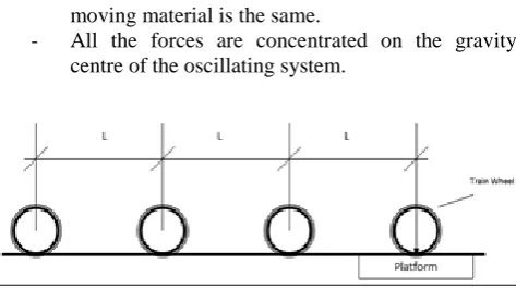
Let us admit that (Figure 03):
- The distance between the wheels’ axes of the moving material is the same.
- All the forces are concentrated on the gravity centre of the oscillating system.
Figure 3: Scheme of transmission of loads on the platform
The general solution of the equation (2) will have the following shape.
With and the resolution of the typical equation: The two first parts of the equation (3) express self-oscillations, which react for a short time and which depend on original parameters. They characterize the oscillation of the way after the passage of the train. The forced oscillations are characterized by the equation:
The first two derivatives of the equation (6) will be:
In order to find C3 and C4 let’s include equations (6) and (7)
in equation (2). The resolution of the system leads to the following equation:
By including equations (8) and (9) in equation (4).
Where a is the amplitude of the strained oscillation and the phase difference between the excitation force and the movement.
Let us use (8) and (9) to find .
Therefore, the angle shall be (
) By squaring the left and right parts of equations (8) and (9), and by factorizing we will obtain the following results:
√ Let us precise that is the application frequency of the pressure from the wheels of the moving material.
The strength application period in point A (Figure 3):
That is:
With V the Trains’ moving speed and L the distance between the wheels’ axes
Let’s go back to the equation (1) and perform some differentiation:
After an oscillation period, the ballast particle falls on the platform at a speed equal to .
By replacing (16) and in the
equation, we get:
The platform speed during the collision can be defined in differentiating the equation (10)
Which makes:
characterizes the collision moment.
The acceleration of the platform can be defined by differentiating the equation (19)
We obtain:
4.
Condition for the detachment of the ballast
particle
Considering F as the bond strength between the ballast particle and the platform (Figure 4).
⃗ ⃗⃗⃗⃗ ⃗ With g the gravity acceleration, accelerator of the particle
under free fall and Z''
the acceleration of the sinusoidal movement of the platform.
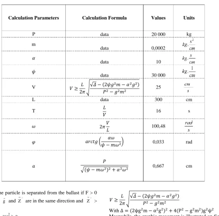
Table 1: Calculation Parameters
Therefore the particle is separated from the ballast if F > 0
in this case g and Z''
are in the same direction and Z''
>
g
That is: a2 > g.
Considering the (13) formula, one obtains:
√ By solving that equation in 2, and considering (p2 – g2m2) > 0 (in fact the exciting force P is significantly superior to the weight of the moving mg; and by replacing by
L V 2 π T
2 π
ω in relation (15), we obtain:
√√
With
Meanwhile, the graphic movement is illustrated on figure 5 in case the movement of the ballast particle is periodic. The ballast particle always takes off after collision, at the same height, and meets the platform once between two intervals of its movement; and this takes place at the same level. During the collision, the timing meter goes back to the origin (t0 = 0) for the movement of the ballast particle.
Figure 5: vibratory movement of the ballast and the platform
Calculation Parameters Calculation Formula Values Units
P data 20 000 kg
m
data 0,0002
𝛼
data 10
𝜓
data 30 000
V 𝑉 𝐿
𝜋√√
𝛥 𝜓𝑔 𝑚 𝛼 𝑔
𝑃 𝑔 𝑚 25
L data 300 cm
T 𝐿
𝑉 16 s
𝜔 𝜋𝑉
𝐿 100,48
𝜑 𝑎𝑟𝑐𝑡𝑔 ( 𝛼𝜔
𝜓 𝑚𝜔 ) 0,033 rad
𝑎 𝑃
15
5.
Conclusion:
Thanks to the vibro-dynamic approach in understanding the phenomenon of the platform and the interface of the railway ballast, we have been able to describe the physical phenomena which are observed during the passage of trains at a reasonable speed. As far as the separation of the components of the ballast from the platform is concerned, it all depends on the combination of the train’s speed, and the basic parameters of the railway which are : the ballast mass which contributes to the vibration, the geotechnical features of the platform (an exclusively grainy area, or an area that must contain a certain cohesion in order to reduce the risks for separation), and finally, the capacity of the platform to soften the vibrating movement. It will therefore be important to precise that the scientific goal of this article is to understand the mechanics of the ballast layer. This will enable us to describe the ballast role under the train passage. From a practical point of view, this study highlights the importance of the types of the platform, given the combinations of the vibrating systems which tend to favor the separation of grains. This implies that attention be given to the nature of the platform which would strongly depend on some specific geotechnical characteristics.
References:
[1] Zeng Zhi-ping, Luo Jun, Meng Xiao-bai, Song Shan-yi and Lin Zhi-hua. 2016. Dynamic Properties of Subgrade of Ballastless Track of High-Speed Railway. EJGE Vol 21.
[2] Openguei K. A. 1923. Revue générale sur le chemin de fer. Gostexizdat
[3] Chaxounianc G. M. 1961. Chemin de fer. Transgelizdat [4] Ornatskii N. B. 1962. Mécanique des sols. Edition
Moscovkii. Gassoudarveneii Universitet
[5] Kandaourov I. I. 1966. Mécanique du milieu granuleux et son utilisation dans les constructions. Stroiizdat [6] Patrick Paultre 2004. Dynamique des structures –
Application aux ouvrages de génie civil. Hermès-Lavoisier