ISSN: 2231-5381
http://www.ijettjournal.org
Page 93
Dynamic (Vibrational) and Static Structural
Analysis of Ladder Frame
Ketan Gajanan Nalawade1, Ashish Sabu2, Baskar P3
School of Mechanical and building science, VIT University, Vellore-632014, Tamil Nadu, India
Abstract
—
Automotive chassis is the back bone of an automobile, which acts as the frame to support the body and other different parts of the vehicle. It is the most crucial element that gives strength and stability to the vehicle under different conditions. So the frame should be extremely rigid and strong so that it can withstand shocks, twists, stresses and vibrations to which it is subjected while vehicle is moving on road. Thus strength and stiffness are the two important design considerations. In this paper static structural analysis and model analysis of a Tata 407 truck chassis is done. Since it is easy to analyse structural systems by finite element method, the chassis is modelled using CATIA and the finite element analysis is done using the ANSYS workbench.Keywords— Ladder frame, model (Dynamic) analysis, Structural
analysis
I. INTRODUCTION
The French term Chassis was initially used to denote the frame parts or basic structure of the vehicle. It is the back bone of the vehicle. Automobile chassis usually refers to the lower body of the vehicle including the tires, engine, frame, driveline and suspension. [1] Out of these, the frame provides necessary support to the vehicle components placed on it. Also the frame should be rigid enough to withstand shock, twist, vibrations and other stresses. The components of the vehicle like engine, transmission system, axles, wheels and tires, suspension, controlling systems and also electrical system parts are mounted on the chassis frame. The loads acting on a chassis includes weight of vehicle and passengers, load due to road camber, side wind, cornering, engine torque, braking torque, load due to road obstacles and finally the load due to collisions.
Even though the backbone frame and unibody frames are available, the ladder frames are commonly used for heavy commercial vehicles because of their superior load carrying capacity. The main components of ladder frames includes longitudinal members and cross members. The frame is made upswept at front and rear to accommodate the springing action of suspension system. The frame is narrowed at front to have better steering lock. Ladder frames also consists brackets to support body and dumb iron to act as bearing for spring shackles. The various cross sections used in frame construction includes channel, box, hat, double channel and I-section.
The ladder chassis frame consists of side members attached with a series of cross members. The critical point at which the maximum stress occurs can be found out by stress
analysis of the frame using finite element method. The critical point is the main factor that causes the fatigue failure of the frame. The magnitude of the stress can be used to decide the life of the truck frame . The accuracy of prediction life of truck chassis is depending on the result of its stress analysis.
In this paper static structural analysis and model analysis on the ladder chassis is done. The static structural analysis includes identification of maximum stressed area and also the torsional stiffness. Model analysis includes determination of natural frequency and mode shape.
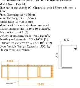
II. BASICDIMENSIONSOFTHELADDERCHASSIS Model No. = Tata 407
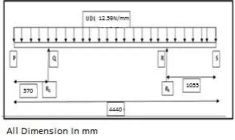
Side bar of the chassis (C- Channels) with 130mm x55 mm x 4 mm
Front Overhang (x) = 570mm Rear Overhang (z) = 1055mm Wheel Base (y) = 2815 mm
Material of the chassis is Structural steel Elastic Modulus (E) =2.10 x 10⁵ N/mm2[2] Poisson Ratio = 0.31[2]
Density of structural steel= 7850 Kg/m3[2] Tensile yield strength = 2.5 x 10⁸ Pa [2] Ultimate tensile strength = 4.6 x 10⁸ Pa [2] Gross Vehicle Weight Capacity =5700 kg (Taken from Tata manual)
Fig 1 Ladder frame dimensions
III.CALCULATIONOFLOADINGANDBOUNDARY CONDITIONS
ISSN: 2231-5381
http://www.ijettjournal.org
Page 94
So this load is divided into two parts as a pressure load oneach of the longitudinal member.
= 2850 Kg
=
= 0.125939 N/mm2
=
1.23469x10⁵PaIV.CADMODELOFLADDERCHASSIS
Fig 2 Model of ladder chassis
The modeling of the ladder chassis frame is done using Catia V5 (Fig 2). The created model is then imported into Ansys workbench.
V. ELEMENTSANDNODES
The meshed truck chassis model has 58130 elements and 152798 nodes. To get better result in critical region fine meshing is done. Finite element analysis is carried out on steel frame as well as E-glass composite and from that analysis the equivalent stress, maximum shear stress, displacement and maximum elastic strain were determined.
Fig 3 Mesh in ANSYS
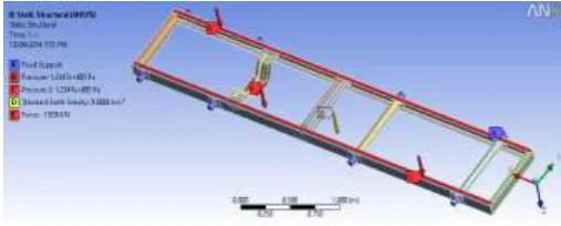
VI.BOUNDARYCONDITIONS
Fixed support has been given at the contact point of leaf spring to the frame in the front and rear because the leaf spring is the one which is going to transfer vehicle load to the tire.
Fig 4 Boundary condition and load
In the Fig 4 point A represents the fixed supports at front and rear. B and C represent the pressure loads on the two longitudinal members. D is the center of gravity of the vehicle through which whole weight of the frame acts. Also one third of the engine weight acts at cross member E.
VII. PROCEDURE
To analyze the ladder frame it is required to import into any analysis software package. Here Ansys workbench has been selected and followed the following procedure; [2][3][4]
1. Created the project for the modal analysis and selected the material from engineering data.
2. Mechanical modal is specified meshing properties are specified to create mesh.
3. After generating the mesh boundary condition such as fixed supports (loading conditions and center of gravity for structural analysis only) has given. 4. Update the project for the given boundary conditions
and results are obtained.
VIII.RESULTS
After carrying out the analysis on the frame with structural steel and E-Glass composite the results are obtained as follows.
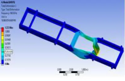
1. Modal Analysis
For the modal analysis of the frame the boundary conditions are given as fixed support only. It is not required to give the other boundary conditions like loading and acceleration due to gravity. The modal analysis is carried out on structural steel and mode shape is obtained as follows.
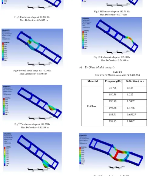
a) Structural steel modal analysis
TABLEII
RESULTS OF MODAL ANALYSIS OF E-GLASS
Material Frequency(Hz) Deflection(m)
Steel
90.394 0.2497
181.52 0.85264
171.29 0.69468
183.72 0.85272
185.71 0.37702
ISSN: 2231-5381
http://www.ijettjournal.org
Page 95
Fig 5 First mode shape at 90.394 Hz, Max Deflection= 0.24977 m
Fig 6 Second mode shape at 171.29Hz, Max Deflection= 0.69468 m
Fig 7 Third mode shape at 181.52Hz Max Deflection= 0.85264 m
Fig 8 Fourth mode shape at 183.72Hz Max Deflection= 0.85272 m
Fig 9 Fifth mode shape at 185.71 Hz Max Deflection= 0.37702m
Fig 10 Sixth mode shape at 189.88Hz Max Deflection= 0.56569 m
b) E- Glass Modal analysis
TABLEI
RESULTS OF MODAL ANALYSIS OF E-GLASS
Fig 11 First mode shape at 94.795 Hz Max Deflection= 0.44184m
Material Frequency(Hz) Deflection ( m )
E- Glass
94.795 0.448
180.38 1.222
190.99 1.5037
193.38 1.4736
185.71 0.65727
ISSN: 2231-5381
http://www.ijettjournal.org
Page 96
Fig 12 Second mode shape at 180.38Hz, Max Deflection= 1.222 m
Fig 13 Third mode shape at 190.99z Max Deflection= 1.5037m
Fig 14 Fourth mode shape at 193.38Hz Max Deflection= 1.4736 m
Fig 15 Fifth mode shape at 194.62 Hz Max Deflection= 0.65727m
Fig16 Sixth mode shape at 198.85Hz Max Deflection= 1.0087 m
2. Static Structural Result Of Frame a) Steel
For structural analysis of the frame boundary conditions are given as fixed support, loading condition (pressure along longitudinal members) and the acceleration due to gravity as mentioned in the previous section.
Fig 17 Equivalent Elastic Strain (m\m) Max strain =0.0013984
ISSN: 2231-5381
http://www.ijettjournal.org
Page 97
Fig 19 Max. Shear Stress (Pa) =1.5376 X 10⁸
Fig 20 Max .Equivalent Stress= 2.7968 X 10⁸
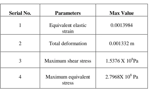
TABLE II
RESULTS OF STATIC STRUCTURAL ANALYSIS OF STEEL
Serial No. Parameters Max Value
1 Equivalent elastic
strain
0.0013984
2 Total deformation 0.001332 m
3 Maximum shear stress
1.5376 X 10⁸Pa
4 Maximum equivalent
stress
2.7968X 10⁸ Pa
b) E-Glass Structural analysis
For structural analysis of the frame made of E-glass boundary conditions are given as fixed support, loading condition (pressure along longitudinal members) and the acceleration due to gravity are given.
Material: - E-Glass Composite [5] Density =2500Kg/m3
Elastic Modulus (E) = 70000 Mpa Poisson Ratio = 0.2
Tensile Yield Strength= 2500 Mpa
TABLE III
RESULTS OF STATIC STRUCTURAL ANALYSIS OF E-GLASS
Fig 21 Equivalent Elastic Strain (m\m) Max strain =0.0039084m/m
Fig 22 Total Max Deformation= 0.003808 m
Fig 23 Max. Shear Stress (Pa) =1.4986 x 10⁸
Fig 24 Max .Equivalent Stress= 2.7959 X 10⁸
IX.CALCULATION
To do the calculation we have simplify the actual model as shown in Fig 25 as simply supported beam by considering beam has been supported by axels
Serial no.
Parameters Max Value
1 Equivalent elastic strain 0.0039084
2 Total deformation 0.003808 m
3 Maximum shear stress 1.4986 X 10⁸Pa
ISSN: 2231-5381
http://www.ijettjournal.org
Page 98
Fig 25 Simplified Model of Frame
Reaction at Q
RQ =
=
RQ = 23134.29 N
Reaction at R
RR =
=
= 32765.30N
The Moment for inertia around the x-x axis for cross section shown in Fig 1
= = 2352229.33mm4
Ib1= Ib2= 2352229.33mm4
Moment of inertia for two round cross bars, Ib3 = 2943925.215 mm4
Moment of inertia for remaining cross bars, Ib4 = 6414558.008mm4
Total mass moment of inertia
= (2352229.33 2) + 2943925.215 +6414558.008 = 14062941.88 mm4
To find out the deflection double integration method is used
EI =Bending Moment
Where E = Young’s Modulus and I=Moment Of Inertia
After double integrating above equation we gets
EIy ∬
So finally we get equation as
EIy
Where are constant which are found out by
boundary condition as deflection at Q and R are zero so finally we get
6106784625 3.536242236 X 10¹²
After finding the constant in theequation to find out the maximum deflection of beam in between support take the
equation of the slope and equate it to zero and find out the value of x where deflection will be maximum as follows
EI =0 and we get three values as
= -155.83 mm
= 1902.71 mm
= 3370.039 mm
and values are not in the span of beam in which
deflection has been considered so those values has been exclude and considered the value of = 1902.71 mm
and put this value in equation
EIy
and gets maximum deflection
= - 1.98 mm
This is maximum deflection produce in frame which is slightly deviated from analysis value because of difference in assumption and physical condition but still it is under limit.
X. CONCLUSION
The modal analysis and static structural analysis on the Tata 407 ladder chassis was carried out. From the above results of steel and E-glass the maximum shear stress and equivalent stress generated in E-glass is under acceptable limit and the total deformation is also within the limit. So we conclude that for the same load carrying capacity we can use E-glass instead of steel for the manufacturing of ladder frame and thereby ( mass of steel frame 170.45 Kg and E-Glass= 54.28Kg) able to reduce the weight by 60-68% and increase the stiffness of frame.
REFERENCES
[1] Shashidhar Dasi and Balakrishnan Mariappan Ashok Leyland Technical Centre. “Local Non-Linear Analysis of Heavy Commercial Truck Chassis Assembly using Sub-Modeling Technique” SAE International 2013-01-2780 Published 11/27/2013
[2] Vijaykumar V Patel1and ,R. I. Patel, “Structural analysis of a ladder chassis frame” World Journal of Science and Technology 2012, 2(4):05-08ISSN:2231–2587
[3] Monika S. Agrawal, Md. Razik “Finite Element Analysis Of Truck Chassis” International Journal Of Engineering Sciences & Research Technology December, 2013] Issn:2277-9655p.G.No.76-85
[4] M. Ravi Chandra1, S. Sreenivasulu, Syed Altaf Hussain “Modeling and Structural analysis of heavy vehicle chassis made of polymeric composite material by three different cross sections” International Journal of Modern Engineering Research (IJMER) Vol.2, Issue.4, July-Aug. 2012 pp-2594-2600
[5] JPS Composite Materials Corporate Headquarters and USO
[6] S.Ramamrutham R.Narayanan “ Strenghth of Material” Dhanpat Rai Publication Delhi