Adaptive Post-silicon Server Validation using Machine
Learning
Paidipeddi Pridhiviraj
Department of ECE, National Institute of Technology Warangal,
India
Tomar Dheerendra S
Server System Validation Group Intel Corporation Bangalore,
India
P Muralidhar
Department of ECE, National Institute of technology, Warangal,
India
ABSTRACT
This paper mainly focuses on providing solutions for efficient feature validation. Modern day server processors and computer systems are developed with billions of transistors. Validation of such a complex systems is playing a crucial role in current research. Pre-silicon validation is not enough to get a full system functional coverage. Post-silicon validation is a necessary step to validate these complex systems and to determine the escaped functional silicon bugs during pre-silicon validation. During post-pre-silicon validation in order to get a full system functional coverage there are more number of features for testing. Applying all the features manually and going through the each test results is difficult to maintain. In order to reduce resource requirements for determining test failure signature, and to reduce the time to debug the failure, introduced the machine learning in current validation environment. The proposed validation algorithm in this paper, which is very useful in feature validation of server processer’s and is adaptive to the previous validation learning’s. Validation is mainly carried out for power management features provided by Advanced Configuration and Power Interface specification. The functional coverage implemented for important power management features namely processor power states, processor performance states and thermal states. This feature coverage analysis is provided through graphical plots.
General Terms
Algorithm, Functional coverage, Machine learning, Processor Power and Thermal management, Validation
Keywords
Adaptation, Debugging, Feature, Functional coverage, Learning set, Machine learning, Pre-silicon, Post-silicon, Power management, System under test (SUT), Thermal management and Validation.
1.
INTRODUCTION
Chips containing millions of transistors are the silicon brains inside the mobile, desktop and server platforms. Validation of these systems confirming that, those should be verified functionally before releasing into market. Now a days the research and development also focuses on ensuring the correct operation and functionality of systems despite of rising levels of the design complexity. So these efforts led to increasing the advances in the theory and practice of design and logic verification before and after manufacturing of digital systems over several decades [1-2]. Validation mainly contains two phases, one is pre-silicon and other is post silicon validation. Pre-silicon verification techniques are mainly simulation, emulation and formal verification tools are limited in scope
and volume. The main drawback of pre-silicon verification is, the current pre-silicon verification technologies and tools are not sufficient for full system functional verification. So Post-silicon validation is a necessary step in a full system functional validation process [3]. Pre-silicon verification models such as simulation and emulation are having excellent controllability, repeatability and observability and hence easy to debug. It is not sufficient to get more functional coverage of system. Post-silicon validation has insufficient controllability and observability due to limited access to internal signals and hence difficult to debug, but it gives system level functional coverage.
Post silicon validation is not a new innovation or idea and it is being used in many industry system validation areas for many years. Post silicon validation is mainly focuses on detecting and fixing the functional bugs of systems after manufacture. Due to high design complexity it is impossible to detect all these functional bugs before manufacture, which are those escaped in pre-silicon verification [4]. Post silicon validation goes through four steps. The validation of server processor is carried for the power management features provided by advanced configuration and power interface (ACPI). 1. Initially detecting the problem by running the test suites containing combinations of these features, on server or system under test (SUT), for a long time until a system failure occurs. 2. According to problem, need to localize the system failure to a small region of the system. 3. Have to identify the root cause of the problem. 5. According to the root cause, need to fix or bypass the problem through patching and circuit editing etc. [5].
simultaneously (concurrency). After maximizing the system stress, some functional bugs will come. These failures need to debug and fix them in subsequent product families.
2.
POWER MANAGEMENT FEATURES
System power management is a global feature, which is built around a standard specification called advanced configuration and power interface specification (ACPI). The main purpose of system power management is to switch the systems into lower-power state when inactive. The main reasons behind to use power management in computing devices is to reduce overall power consumption, cooling requirements and to increase battery life and performance [6]. The power management of computing systems is done in two levels, one is in processor level and the other is in operating system (OS) level. In the OS level, when system is in hibernate mode it moves the contents of RAM into hard disk and completely switches off the system to save the power. In the processor level, CPU core voltage and clock rate are the two important parameters of processor are altered in real time to decrease the power consumption at the cost of lowering the performance. These two variations are called dynamic frequency and voltage scaling [7].
ACPI is an interface specification, which is comprised of both software and hardware elements. As ACPI document states that “The Advanced Configuration and Power Interface (ACPI) specification was developed to establish industry common interfaces enabling robust operating system (OS)-directed motherboard device configuration and power management of both devices and entire systems”. This interface specification is suitable to all computing devices including mobile, desktop, workstation and server machines. ACPI includes global system states, device power states, processor performance states (pstates), processor power states (cstates) and thermal states [8].
Global system states:
These states apply to the entire system and these are visible to the users. G0 is the working state, where the processor and all peripheral devices are in running state and consumes more power. G1 is the sleeping state where computer consumes less power and most of the system context is saved by the hardware and software. G2 is the soft off state where computer consumes minimal amount of power and no context is saved by the hardware. G3 is the mechanical off state where no electrical current passed through circuitry and power consumption is zero except for real time clock. OS restart is required for G2 and G3 states, not required for G0 and G1 [9].
Processor power states (Cxstates):
These are the processor power consumption states within the global system state G0 (working state). When CPU is idle, it enters into one of the below power saving modes. C0 is the operating state of CPU, where it executes instructions. C1 is the halt state where it stops CPU main internal clocks by software and not executes any instructions. C1E is the enhanced halt state where in addition to stopping CPU clock and reduces CPU voltage for lower power consumption. C2 is the stop clock state, where it stops the CPU main internal and external clocks by hardware.C3 is the sleep state where in addition of stopping clocks and core PLL (phase locked loops), even core cache are flushed. C6 is a deep power down state, where core PLL are off, core cache is flushed and CPU voltage is reduced to 0v [10].
These core cstates are extending up to C10 in modern server processors. When all the cores are in a particular cstate, then it is called package cstate like PC3 (package C3 state) and PC6 (package C6 state), are the examples of package cstates. So C0 to C6 are the processor power states, where each of these states consumes less power by cutting CPU clock and reduces the voltage [11].
Processor performance states (pstates):
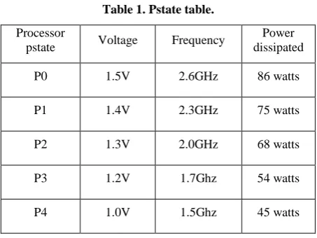
In the modern day servers the power consumption of intel processor is approximately 30 % of total power dissipation. In order to save power when system is in working state (G0), and the processor is in operating state (C0) intel develops a new technology called Enhanced speed step technology, also called as demand based switching or GV3(Geyserville) technology [12]. By using dynamic voltage and frequency scaling concepts operating system alters the voltage and frequency to trade-off the power and performance constraints. So operating system continuously monitor’s CPU utilization, it reduces the CPU speed when it is in idle state and increasing the speed whenever load increases. Processor performance states or pstates are a pre-defined set of voltage and frequency combinations at which a CPU can run for optimum power and performance. Pstates are in the order of P0, P1, P2 ….Pn. P0 is the highest frequency and consumes more power, Pn is the lowest frequency and consumes very less power. These frequency variations are altered by OS depends on work load by using model specific register’s (MSR). The register IA32_PERF_CTL is used for changing the frequency of CPU by writing a pstate value to the lower 16bits of register. And to monitor the CPU frequency, OS reads the lower 16 bits of IA32_PERF_STATUS register. Table 1 is the example of how pstates combinations are looks like, for optimum power and performance levels. Where power dissipation is the product of squared voltage and frequency [13].
PαV2
F where P-power, V-voltage and F-frequency.
Table 1. Pstate table.
Processor
pstate Voltage Frequency
Power dissipated
P0 1.5V 2.6GHz 86 watts
P1 1.4V 2.3GHz 75 watts
P2 1.3V 2.0GHz 68 watts
P3 1.2V 1.7Ghz 54 watts
P4 1.0V 1.5Ghz 45 watts
Thermal states:
the thermal management. These two are independent and isolated temperature sensors. The thermal diode is mainly monitor’s processor temperature, and help in asserting PROCHOT signal when processor reached its maximum operating temperature. Once PROCHOT signal is asserted thermal control circuit is enabled, which controls the CPU temperature by clock modulation. IA32_THERM_STATUS is the architectural MSR used for measuring the CPU temperature. If CPU temperature reaches the catastrophic point, the THERMTRIP signal is asserted and when THERMTRIP is active, the processor will catastrophically shut down [14-16].
3.
CURRENT VALIDATION
METHODOLOGY
The current validation methodology is shown in Figure 1.
Results
Apply
Test
System Under
Test(SUT)
Figure 1. Current validation methodology
Procedure is applying test case to server or SUT. Get the results.
Manually verifying the results and test status pass or fail. Have to identify the root cause of the issue.
Need to Fix or bypass the problem by patching and circuit editing etc.
But in real time, the test is failed due to many variables. If the test is failed due to original functionality it is called actual failure. If the test is failed due to any other variables it is called false failure. In real time execution there are high number of tests are applied to SUT. Going through each & every failure is also difficult. So introduced the machine learning in current validation methodology to simplify the validation & debug framework and to reduce man power and resource requirements. The validation environment that learns from the previous validation experience.
Machine learning –is a concept in which it models a particular problem through the use of set of input and output data sets, instead of using the underlying actual system responses and equation’s etc, because in real time most of the real world problems knowing the system dynamic’s and building the ideal system model is not an easy task. In such cases machine learning techniques eases the modelling task [17-18]. In the current validation, input test cases and possible output results are known. In the next section it contains proposed validation framework, which is modelled using these input test cases and possible test results. And the algorithm is suitable for validation and reduce the time to triage and to debug the failures. The algorithm is adaptive to previous validation data of server processor’s.
Many of the machine learning algorithms are inspired directly from the nature. Fuzzy logic uses the human vague thinking, Artificial neural networks uses the brains massive parallelism, Simulated Annealing uses the slow cooling process in metallurgy, Genetic algorithms adopted the survival of fittest concept etc. So machine learning algorithms are also known as soft computing methods [19].
Machine learning algorithms are classified into many forms based on how the algorithm treated the inputs. Those are supervised learning and unsupervised learning, etc. Nowadays machine learning algorithms are used in many areas like data mining, medical diagnosis, stock market analysis, OCR, computer vision, search engines [20]. The post silicon system validation field has been slower to adopt the modern machine learning techniques as compared to the degree seen in other fields.
4.
PROPOSED VALIDATION
FRAMEWORK
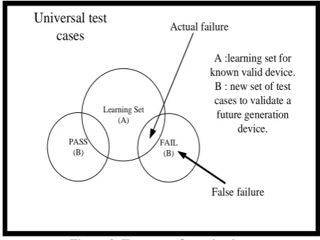
The current validation methodology has many drawbacks those are discussed in the last section. In order to simplify the debug and validation framework, the proposed validation framework introduced the machine learning in current validation. That means validation methodology learns from the previous validation learnings. The proposed validation framework is developed based on the Venn diagram described on figure 2.
Universal test
cases
A :learning set for known valid device. B : new set of test cases to validate a future generation
device. Actual failure
False failure
PASS (B)
Learning Set (A)
FAIL (B)
Figure 2. Test cases Organization
The Venn diagram contains test cases organization. Universal test cases are the total tests independent of the system and result. In order to validate server processor power management features there needs to be more number of tests have to be applied. These large number of tests results in more failures due to some feature bugs, script failures, and false failures. In order to automate validation the above Venn diagram plays a crucial role.
4.1
Preparation of learning set for a known
valid server processor (A)
The block diagram for the learning set preparation is shown in Figure 3.
Steps for preparing learning set:
Select a known valid server processor (A) or SUT, which was already validated.
Apply a test for specified duration, obtain the result and log the result.
Prepare the learning set depends on the result.
Learning set is a dictionary which contains pairs of tests and results.
If the test passes add it to the learning set.
If it fails, test is not a valid one because device (A) is valid. Apply another test.
Repeat the above procedure until all the test features are over.
Known device(A)
Is result pass?
Test Result
Learning set Change test
pass
fail
Figure 3. Learning set preparation for a known valid device (A)
Test feature command line is pm_test_suit.py --xmlFile=pm_test.xml --iteration=5 --time=6 --test=@program_feature
Pseudo code for developing learning set:
for i=0 to M
Feature (F) =L[i]
Command line: [pm_test_suit.py -xmlFile=pm_test.xml --iteration=5 --time=6 -- test=@program_feature (F)]
System (command line)
If Result: Pass
Learning set R {feature: [F, Result]}
Else
Continue
Where L=list of features, R=learning set i.e. dictionary, F=feature to be tested, and pm_test.xml file contains program sections each section denotes what combination of features want to test.
So by using the above procedure learning set for a known valid device (A) is prepared, which will be used in the second phase for validation of future server products.
4.2
Proposed Algorithm for validating
server processor or SUT
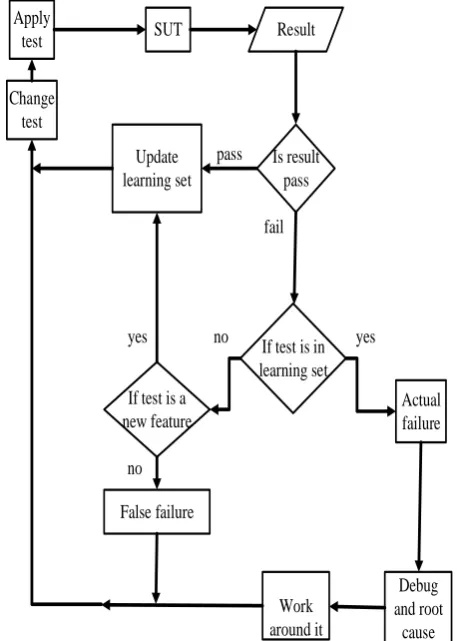
Proposed framework for system validation is shown in Figure 4. By the use of previously generated learning set for a known valid server (A), will validate future generation server processor (B). This proposed algorithm is mainly implemented from the Venn diagram shown in figure 2 which describes the test cases organization. Steps for system validation are
SUT Apply
test Result
Update learning set
Is result pass
If test is in learning set If test is a
new feature pass
fail
Actual failure yes no
Change test
yes
no
False failure
Debug and root
cause Work
around it
Figure 4. Algorithm for validating server processor (B) or SUT and for updating learning set.
Select a future generation server processor (B) for validation.
Apply test to server processor (B) or SUT If test is passed, then update it on the learning set Else if it fails then check whether the test is in the
learning set or not.
If the test is in the learning set, that means the failure is called “actual failure”
If the test is a new feature then update it on the learning set, else if it is not a new feature then the failure is called “false failure”.
Actual failures need to debug and root cause the problem If the root cause of the problem is identified, work
around for the problem and fix it
False failures are not a valid failures. Those failures can leave and rerun the test with necessary steps.
Repeat the above process until all the test features are over.
Figure 5 contains the pseudo code for proposed validation algorithm. Where command line for feature execution is [pm_test_suit.py xmlFile=pm_test.xml iteration=5 --time=6 --test=@program_feature (F)] Where L=list of features, R=learning set i.e. dictionary, F=feature to be tested, and pm_test.xml file contains program sections each section denotes what combination of features want to test.
Pseudo code for proposed algorithm: For i=0 to m
Feature (F) =L[i] Command line:
System (command line) If Result: Pass
Learning set R {feature: [F, Result]} Else if feature (F) not in the learning set R: Learning set R {feature: F}
Else if feature (F) in learning set R: #actual failure section Case A: functional failure
Feature (F) Actual failure Debug ( ); //manual debugging Break;
#false failure section
Case B: false failure variables //Refer Table 2 Feature (F) False failure
Continue;
Figure 5. Pseudo code for proposed validation algorithm
The above algorithm each time it updates new input data features and their corresponding results. And also it gives failure signature and whether it is an actual failure or false failure. While validating this server product (B), updated the learning set. So updated learning set is useful for validation of future server products. So each time, validation framework do the validation through the use of previous validation learnings.
5.
RESULTS AND DISCUSSIONS
By using the above proposed validation framework did the validation of server processor mainly for power management features of ACPI. Those features include processor power states (cstates), processor performance states (pstates), device power states, link states and thermal states are explained in power management features section. These features are global features and there are many other features in component level are validated by using the above validation framework.
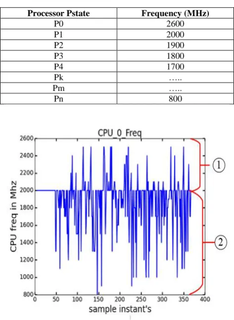
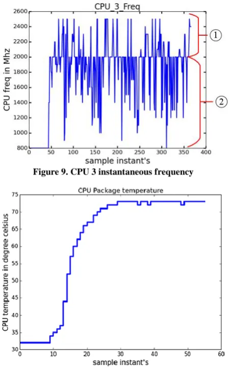
Example features of power management are shown in below. Figures 6-9 shows pstates (processor performance states) feature. Pstates feature nothing but running the CPU with different pstates (or frequencies) to reduce power
consumption. By continuously writing the random pstates to the IA32_PERF_CTL MSR fields, the CPU will run with corresponding frequencies specified by the datasheet. The Intel’s CPU core frequency is measured by using IA32_PERF_STATUS architectural model specific register (MSR) fields. Figures 6-9, these all plots are CPU frequency plots measured when testing pstates feature on a Xeon-D server system having 8 cores i.e. 16 CPU’s (each core having two threads). On all 16 CPU’s frequencies are measured. Four of the frequency plots shown in figure 6-9. These plots covers the pstates coverage and help in showing the pstate transitions. This coverage plots help in debugging the functional failures.
Table 2 is the pstate table for Xeon-D server system. Where [P0-P1] Turbo frequency range-[2600-2000] and [P1-Pn] Non Turbo frequency range-[2000-800]. In all the four frequency plots processor transition between turbo frequency clips as well as non-turbo frequency range for optimum power and performance levels [21].
In all the frequency plots (Figure 6-9)
Range 1Turbo frequency clips [2600-2000]
Range 2 Non-turbo frequency range [2000-800].
These transitions indicate pstates feature is functionally covered.
Table 2. Xeon D Processor Pstate table Processor Pstate Frequency (MHz)
P0 2600
P1 2000
P2 1900
P3 1800
P4 1700
Pk …..
Pm …..
Pn 800
Figure 7. CPU 1 instantaneous frequency
Figure 8. CPU 2 instantaneous frequency
Figure 9. CPU 3 instantaneous frequency
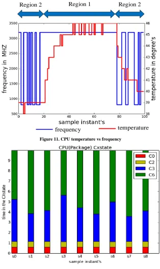
Figure 10. Thermal states feature
Similarly thermal states means different operating environment temperatures near the CPU. The CPU
temperature is measured using
Region 2
Region 1
Region 2
temperature
frequency
Figure 11. CPU temperature vs frequency
Figure 12. CPU Package Cxstates
One more example feature called CPU Cxstates (processor power states). To test this feature, need to vary the cstates continuously from C0 state to C6 state. Figure 12 describes the amount of time that CPU spend in that package cstate when varying cstates feature. To calculate the percent of time in CX state= MSR_PKG__CX_Residency/TSC. Where TSC is Time Stamp counter MSR (0x10H) and MSR_PKG_CX_RESIDENCY is a MSR which gives residence counter of CX states since last reset of CPU.
For example to Calculate the percent of time in PC6: %PC6_time = MSR_PKG_C6_RESIDENCY /TSC.
The graph (Figure 12) plotted for 9 sample instants with
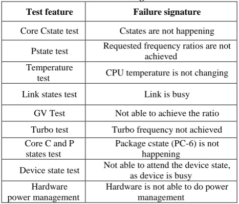
Table 3. Some tested features and their corresponding “Actual Failure” signatures
Test feature Failure signature
Core Cstate test Cstates are not happening
Pstate test Requested frequency ratios are not achieved
Temperature
test CPU temperature is not changing
Link states test Link is busy
GV Test Not able to achieve the ratio
Turbo test Turbo frequency not achieved Core C and P
states test
Package cstate (PC-6) is not happening
Device state test Not able to attend the device state, as device is busy
Hardware power management
Hardware is not able to do power management
Table 4. Some false failure signatures False failure signature’s
Not a new feature of ACPI CPU is locked
Insufficient memory
Wrong command line was picked up
Actual failures are mainly due to functional failures. Functional failures may be because of script failures, silicon bugs or software bugs. These functional failures need to debug and root cause the problem. Fixing the issue is final step in validation. False failures are due to so many variables, these failures are any failures other than actual failures. The algorithm is adaptive to the previous validation learnings. Each time if a future generation server processor is needs to validate, learning set plays a crucial role, then correspondingly the algorithm is suitable for validation, to triage the failures and reduce the time to debug.
6.
CONCLUSIONS
So this paper contains validation framework that is suitable for post silicon server validation, and also validation is mainly carried out for power management features provided by Advanced Configuration and Power Interface specification (ACPI). Proposed and implemented the feature functional coverage for important power management features. Feature functional coverage is mainly implemented for processor power states (package cstates), processor performance states (pstates) and thermal states. The algorithms for functional coverage implementation is provided. Feature functional coverage analysis is provided through graphical plots. These plots will clearly explain whether these features are functionally covered or not. These functional coverage plots are taken when testing the features in real time execution environment.
7.
REFERENCES
[1] Subhasish Mitra , Sanjit A. Seshia, and Nicola Nicolici, Post-Silicon Validation Opportunities, Challenges and Recent Advances. Design Automation Conference (DAC), 2010 47th ACM/IEE
[2] Intel Platform and Component Validation A Commitment to Quality, Reliability and Compatibility. http://www.intel.com/design/chipsets/labtour/pvpt_white paper.htm
[3] Amir Nahir, Avi Ziv, Rajesh Galivanche, Alan Hu, Miron Abramovici, Bob Bentley, Valeria Bertacco, Albert Camilleri, Harry Foster, and Shakti Kapoor “Bridging Pre-Silicon Verification and Post-Silicon Validation” DAC'10, June 13-18, 2010, Anaheim, California, USA. ACM 978-1-4503-0002-5/10/06
[4] Adir, S. Copty, S. Landa, A. Nahir, G. Shurek, A. Ziv, C. Meissner, and J. Schumann, ‘‘A unified methodology for pre-silicon verification and post-silicon validation,’’ in Proc. Design Autom. Test Eur. Conf. Exhibit., 2011, DOI: 10.1109/DATE.2011.5763252.
[5] Pridhiviraj Paidipeddi and Dheerendra Singh Tomar “Machine Learning Adaptation in Post Silicon Server Validation” International Journal of Applied Information Systems (IJAIS) – ISSN: 2249-0868 Foundation of Computer Science FCS, New York, USA, Volume 7– No.11, November 2014 – www.ijais.org
[6] Intel® Performance Counter Monitor - A better way to measure CPU utilization. https://software.intel.com/en-us/articles/intel-performance-counter-monitor
[7] White Paper: Power Management in Intel® Architecture Servers, April 2009
[8] Advanced configuration and power interface specification, Revision 5.0a, November 13, 2013
[9] http://acpi.info/spec.htm
[10]Jonathan A. Winter , David H. Albonesi , Christine A. Shoemaker, Scalable thread scheduling and global power management for heterogeneous many-core architectures, Proceedings of the 19th international conference on Parallel architectures and compilation techniques,
September 11-15, 2010, Vienna,
Austria [doi>10.1145/1854273.1854283]”
[11]Intel® Turbo Boost Technology in Intel® Core™ Microarchitecture (Nehalem) Based Processors, white paper
[12]Stuart Hayes | Enterprise Linux Engineering, Controlling Processor C-State Usage in Linux. A Dell technical white paper describing the use of C-states with Linux operating systems
[13]White paper: Enhanced Intel® SpeedStep® Technology for the Intel® Pentium® M Processor, March 2004, Order Number: 301170-001
[14]Understanding Power Management of Intel® Processors for Mil/Aero Applications, cutriss wright controls, Embedded computing
[15]E. Rotem, A. Naveh, et al., “Analysis of Thermal Monitor features of the Intel Pentium M Processor”, Proceedings of TACS-01, ISCA-31, 2004.
[16]A. Naveh, E. Rotem, et al.,”Power and Thermal Management in the Intel® Core™ Duo” , Intel Technology Journal Vol. 10 #2, 2006. ITJ MY
http://www.intel.com/content/www/us/en/architecture- and-technology/64-ia-32-architectures-software-developer-instruction-set-reference-manual-325383.html
[18]Phil Simon (March 18, 2013). Too Big to Ignore: The Business Case for Big Data. Wiley. p. 89.ISBN 978-1118638170.
[19]Mitchell, T. (1997). Machine Learning, McGraw Hill. ISBN 0-07-042807-7, p.2.
[20]Andrew DeOrio, Qingkun Li, Matthew Burgess and Valeria Bertacco, Machine Learning-based Anomaly
Detection for Post-silicon Bug Diagnosis, Design, Automation & Test in Europe Conference & Exhibition (DATE), 2013, pp.491.
[21]Wernick, Yang, Brankov, Yourganov and Strother, Machine Learning in Medical Imaging, IEEE Signal Processing Magazine, vol. 27, no. 4, July 2010, pp. 25-38.