IJSRR, 7(3) July – Sep., 2018 Page 1221
Review article
Available online www.ijsrr.org
ISSN: 2279–0543
International Journal of Scientific Research and Reviews
Performance of Series Filter in a Grid Connected Doubly Fed
Induction Generator System
Keerthi V.
1*, Devi Rekha G.
2, Chathurya N.
3, Prasad Venkatesh V.
4Dept. of EEE, Pragati Engineering College Surampalem, Andhra Pradesh India. Email:[email protected], Mob. 9553357337
ABSTRACT
The project deals with performance of the load when the grid connected DFIG wind turbines
with series filter .The proposed technique will analyze the performance of grid when the Series Filter
are placed at transmission line before the distribution of power to the load. It gives the strong grid
scenario by reducing the reactive power consumption from grid side in the system. The commonly
used load is non linear load. In this project performance analysis of a grid was carried on for
distribution with and without Series Filter.
This project is to ensure the corresponding voltage, current and total harmonic distortion
(THD) will be improved at a better level when compared with a grid which is not having any
compensation device to improve the power quality of the system.
The main objective of this project is obtaining the better results in Voltage profile and also
improving the power factor to get the proper electrical bill to the corresponding loads. The Stand
alone operation of the DFIG system with integrated battery energy storage connected across the
DC-link of ac/dc/ac converter is modelled. The connected load consisting of linear load and non-linear
load is modelled. The Grid Side Converter is designed to control frequency and load bus voltage
magnitude using droop control technique.
KEYWORDS:
Series Filter, Doubly Fed Induction Generator(DFIG), Total Harmonic Distortion(THD).*Corresponding Author:
V. Keerthi
UG Scholar,
Electrical and Electronics Engineering, Pragati Engineering College, Surampalem, Andhra Pradesh, India,
IJSRR, 7(3) July – Sep., 2018 Page 1222
INTRODUCTION
Now a days, nothing is possible without electricity. Without electricity modern society would
cease to function. As the volume of power transmitted and distributed increases, so do the
requirements for a high quality and reliable supply. Thus, reactive power control and voltage control
in an electrical power is important for proper operation for electrical power equipment to prevent
damage such as overheating of generators and motors , to reduce transmission losses1 and to
maintain the ability of the system.
Voltage control and reactive power management are the two aspects of a single activity that
both supports reliability and facilitates commercial transactions across transmission networks. Thus
reactive power is essential to maintain the voltage to deliver active power through the transmission
lines.
DOUBLED FED INDUCTION GENERATOR:
The term Doubly Fed refers to the fact that the voltage on the stator is applied from the grid
and the voltage on the rotor is induced by the power converter. This system allows a variable-speed
operation over a large, but restricted, range. The converter compensates the difference between the
mechanical and electrical frequencies by injecting a rotor current with a variable frequency . Hence,
the operation and behaviour of the DFIG is governed by the power converter and its controllers.
The primary advantage of doubly-fed induction generators when used in wind turbines2 is
that they allow the amplitude and frequency of their on the wind turbine rotor. Because of this,
doubly-fed induction generators can be directly connected to the ac power network and remain
synchronized at all times with the ac power network. Other advantages include the ability to control
the power factor (e.g., to maintain the power factor at unity), while keeping the power electronics
devices in the wind turbine at a moderate size.
DYNAMIC MODELING AND CONTROL OF THE DFIG SYSTEM
The traditional wind turbine generator (WTG) systems3 employ squirrel-cage induction generators (SCIGs) to generate wind power. These WTGs have no speed control capability and
cannot provide voltage or frequency support when connected to the power grid. During the past
decade, the concept of a variable-speed wind turbine driving a doubly fed induction generator
(DFIG) has received increasing attention because of its noticeable advantages over other WTG
systems. Most existing wind farms and those in planning employ this type of WTGs. The DFIG wind
turbines can provide decoupled active and reactive power control4 of the generator, more efficient
IJSRR, 7(3) July – Sep., 2018 Page 1223 possible because of the control scheme that can be implemented in the back-to-back converters5 of
the DFIG. Hence, the method of controlling this back-to-back converter plays a significant role in
achieving better performance of the DFIG system.
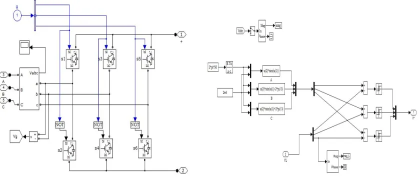
Fig.1: Controlling of Doubly fed induction generator for wind energy conversion system
SERIES FILTERS:
The output of the rectifier pulsating in nature, it consists of a desired DC component of
voltage and unwanted ripple components. These ripple components are removed by placing filter
circuit at the output of the rectifier.
Active power filters have several advantages over passive ones: compensation is automatic,
there is no risk of resonances, unity power factor (or any other desired value) can be achieved
permanently and without disturbing the electrical network, they can compensate for phase unbalance,
and excellent performance can be achieved. They can also be combined with stated power. There are
mainly two types of active power filters: the shunt active filter and the series active filter.
Active power filters are usually controlled by a microcontroller or a digital signal processor
(DSP) with very good results. However, here an alternative for the controller is proposed, based on a
personal computer with a general purpose multifunction data acquisition board included in the PCI
bus. The major advantages of this approach are the relative low cost of the equipment, the high
processing capabilities of the personal computer processor and its versatility, allowing many other
tasks, such as data acquisition and logging, remote access and monitoring, integration with other
systems, and many other possibilities. The methods applied to control the active filters are decisive
in achieving the goals of compensation, in the determination of the filter power rate, and in their
dynamic and steady state performance.
VOLTAGE REGULATION IN SERIES FILTER:
Voltage regulation can be maintained in the power system by supplying or absorbing the
reactive power. Hence, the voltage regulation at a particular node in a power system is directly
the vicinity of that node. Although, the DFIG-based wind turbines are able to control active and
reactive power independently, the reactive power capability of those generators is limited as
discussed. This problem is more severe in the case of DFIG wind turbines connected to weak power
grids6 having under voltage condition as the reactive power capability gets even more degraded.
Hence an additional local reactive power source is needed. Moreover, the power generation trend
these days is shifting from the transmission network to the distribution grid, i.e. De-centralization of
power generation. As a result, it is becoming more difficult to control the voltage in the entire
transmission network from conventional power stations only. Hence grid companies are installing
dedicated local voltage control equipments like capacitor banks, FACTS devices and are demanding
distributed generation equipments to have their own reactive power capability as a result there cannot
be any exemption for wind turbines. Furthermore, because of the increased penetration level of wind
turbines in the power grid, utility companies are asking to fulfill certain criteria (grid codes) for the
interconnection of wind turbines to the power grid.
SERIES FILTERS CONTROLLER:
The operation of the series filter controller is giving gate pulse to the series filter based on
the comparison of voltages. By using multiplexer comparing the reference voltages with actual
voltages giving the corresponding difference between the reference voltages and actual voltages.
The comparison of inputs of 3 phases reference voltages with 3 phases actual voltages getting output
is given to the multiplexer. The getting output is known as the Gate pulse. That gate pulse is given to
the series filter. The operation of series is done based on the operation of switches. Here is the
actual voltages of simulink model and A,B,C are the reference voltages of the simulink model.
IJSRR, 7(3) July – Sep., 2018 Page 1225 Formulae of series RLC filter :
Current equations
IR=IL=IC=I(t)
I(t)=Imsinwt
Voltage equations
Vs2 = VR2+(VL-VC)2 if (VL > VC)
VS2 = VR2+(VC-VL)2 if (VC > VL)
Impedance, Z =(R2+(XL-XC)2)^(1/2)
Power factor = Cosα = R/Z
Sinα = (XL-XC)/Z
tanα = (XL-XC)/R
In this controller IGBTs are used for high power applications. Based on the operation of
switches parameters controlling is achieved. The operation of series filter controller is when the gate
pulse is given to the controller of three phases. When gate pulse voltage is comparing with rated
voltage then battery it used to reduces the difference and gives the output of series filter is giving
input to the load. In series filter thyristors operation based on the sequence (1,6),(2,4),(3,5). Here
NOT gate is used because of reducing the short circuit currents7. If we observed swell then battery
used absorb the voltage and sag is obtained then battery delivered the energy. Isolation transformer
also used to connecting the series filter to the transmission line.
RESULT:
Fig(6) Load Voltage and Load Currents without Fig(7) Load Voltage and Load Currents with
Filter Filter
Fig(8) Power Factor without Series Filter Fig(9) Power Factor with Series Filter
CONCLUSION
In this project, the performance is reliable by using series filter when compare with power
system without series filter in meeting desired load conditions. The performance shows both steady
state condition and transient state condition, also observes the weak grid scenario. The power factor
has also been improved in the case of power transmission with series filter when compared with
power factor without series filter.
REFERENCES
1. The World bank IBRD IDA, “Electric power transmission and distribution losses (% of
output).[Accessed:05-May-2017]
Availablefrom:URL:http://data.worldbank.org/indicator/EG.ELC.LOSS.ZS?end=2014&locat
io ns=SE&page=4 &start=1960&view=chart
2. S. Grunau and F. W. Fuchs, “Effect of Wind-Energy Power Injection into Weak Grids,” in
European Wind Energy Association 2012 Annuan Proceedings, 2012
3. Raymond W. Flumerfelt and Su Su Wang, "Wind turbines," in AccessScience,
IJSRR, 7(3) July – Sep., 2018 Page 1227 4. B. Rabelo, W. Hofmann, J. da Silva, R. de Oliveira, and S. Silva, “Reactive power control
design in doubly fed induction generators for wind turbines,” IEEE Trans. Industrial
Electronics, 2009; 56(10): 4154-4162
5. J. Xu, S. Xie and T. Tang, “Evaluations of current control in weak grid case for grid
connected,” Power Electronics, IET,2013; 6: 227–234
6. A. Etxegarai, P. Eguia, E. Torres, A. Iturregi, and V. Valverde, “Review of grid connection
requirements for generation assets in weak power grids,” Renewable and Sustainable Energy
Reviews, 2015; 41: 1501-1504
7. T. Xia, M. Li, P. Zi, L. Tian, X. Qin, and N. An, “Modeling and simulation of Battery Energy
Storage System (BESS) used in power system,” Proc. 5th IEEE Int. Conf. Electr. Util.