Effective Software Assembly for the Real
time systems using Multi-level Genetic
Algorithm
R.Amuthakkannan
Senior Lecturer,
Caledonian College of Engineering, P.O. Box : 2322 , CPO Seeb 111
Muscat, Sultanate of Oman.
Abstract:
Software Assembly of reusable components is one of the most important processes to improve the reliability of the product in the Commercial Off The Shelf (COTS) software. Software assembly and also continuous improvement of quality in software based systems is an important issue in software development process. In this paper, a multilevel genetic algorithm is used to find the sequence of the assembly order of the software components among the chosen reusable components. In GA, dependency between the components is also considered based on coupling factor and the assembly order of the identified software component is found effectively.
Keywords: COTS software, Software Assembly, Genetic Algorithm, Dependency Chart
1.0 Introduction
Today, the software-based products are commonly used in many industrial systems. There are various methods used to develop the real time software for software based systems. It is most important to develop the real time software with high quality as early as possible to construct a software based systems and also to update the implementation of latest technologies. In large scale software, component based software development playing a vital role to reduce time and also to increase quality. The software development for Commercial Off The Shelf (COTS) software includes planning, analysis, requirements specification, design, implementation, assembly, testing and integration, operation and maintenance. As a consequence, time spent on development of new products or release of the new versions of software products must be reduced. One solution to this emerging problem is to reuse software design, components and solutions in new versions of systems and products. Besides shortening development time, properly handled reused software will improve the quality and specifically reliability since the code is executed for longer time and in different contexts (Fenton and Fleeger, 1996).Moreover, assembly of all the components needs more expertise to get a high quality in the COTS software. This paper aims to give an effective solution for component assembly in Component-Based Software Engineering (CBSE).
2.0 Literature Review
One-way of approaching the issue of reuse is to develop the computer-based systems by the Component-Based Software Engineering (CBSE) or Component Based Software Development (CBSD) is normally done by assembling software systems from components. The use of Commercial-Off-The-Shelf (COTS) products as elements of large software systems is becoming increasingly common place due to shrinking budgets, accelerating rates of COTS enhancement and expanding system requirements (Heineman and Councill, 2001). The integration of COTS software into software based systems introduces many important issues. The primary issue is the assembly of different software components into usable form. The consumers who want to use these systems want reliable software system within the budget and also time bound is an important issue in component-based software.
CBSD can help the software industry to realize the quality and productivity improvement similar to those achieved in electronic and mechanical component assemblies (Brown, 2000; Szyperski, 2003). Vitharana et al. (2003) suggested that the weightage must be given to the cost effectiveness with the ease of assembly model in software industries when the business strategy is low cost and component-based development. He also pointed that the design models with quantified technical features support the component developers’ business strategy. Architecture-based software approach in which the architectural analysis and code synthesis are combined together in order to efficiently and correctly assemble a system out of a set of already implemented components. Bucchiarone et al. (2006) have proposed a software architecture-based approach in which architectural analysis and code synthesis are combined together in order to assemble a system out of a set of already implemented components. According to the past literatures, there is no flexible standard or step by step procedure or proper algorithm to make a perfect assembly in COTS system. In 2007, Vijayalakshmi et al., tried to give a best solution for the component based software assembly in their paper.
Vijayalakshmi et al (2007) proposed a new algorithm for component assembly using dependency chart. It is an excellent algorithm for minimum number of components and it is a time consuming algorithm for large scale software assembly. The dependency based algorithm is taken as a base paper for the proposed problem and it is proposed to solve by using genetic algorithm in this research work.
3.0 Problem background
Software assembly is the process of designing a software system from off-the-shelf components and combining them to form a functional system. This process involves two steps
1. Selection of suitable components from repository 2. Assembly
selected. The result of this process is to reveal the necessary information to make selection and identify possible sources of conflict and overlap, so that the component can be effectively assembled and evolved. The next process after selection is the assembly of the software components. Assembly of the components also needs more expertise to achieve appropriate quality and particularly reliability (Dolbec, J. and Shepard, T.,1995).The following are the objectives of the effective software assembly.
- To increase the reliability of the software by minimizing the defects. - To find a well-defined infrastructure for component based software system.
- To make a better coordination between components in the software architecture.
- To avoid intricacies and complexities in software integration.
- To minimize the overall development time.
- To maintain flexibility of arrangement and operation of components.
- To obtain a cost effective software system.
So, it is most important to concentrate on software assembly and also it is needed to develop a proper algorithm for the assembly process.
4.0 Genetic Algorithm
Genetic algorithms are used to optimize the specified problem using computer simulations. GAs are used to search in the very large space efficiently because of its probabilistic nature rather than deterministic. GA is easy to implement and also to solve intractable problems quickly. GAs start with initial set of random solutions called the population. There is no rule to determine the population size. Then the population will converge to minimize the population size efficiently. Once the population size is chosen, the initial population is randomly generated. The GAs are using three genetic operators-reproduction, crossover, and mutation. The successive generation in GAs are defined using chromosomes. Normally chromosomes with higher fitness value are more likely to be selected. In this work, Genetic Algorithm is used to search the best assembly order in the reusable components of Component Based Software Development (CBSD). In the implementation of the GA in software assembly, dependency between the components is taken as important parameter which is defined by coupling factors.
4.1 Multilevel Genetic Algorithm
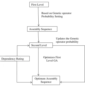
populations, based on Genetic Operator Probability Setting (GOPS). The second level GA optimizes and updates GOPS for the first level GA. Figure 1 illustrates our multi-level genetic assembly planner, in block diagram form. In this, first level assembly sequence selection is dynamically optimized by the second level (level-2) GA GOPS selection.
Figure 1. Multilevel Genetic Algorithm using Genetic Operator Probability Setting (GOPS)
5.0 Dependency based component assembly
In software based system, more components are combined into larger systems, more and more interconnections exist in these collections and relationships between their components become more numerous. Effective and reliable use of these systems involves cooperative operation among the components. Since complex distributed computer systems are composed of larger number of interconnected heterogeneous components from multiple vendors, comprise of any component may potentially affect many other components in unexpected and unacceptable way. (Harry S. Delugach, 2008)
First Level
Assembly Sequence
Based on Genetic operator
Probability Setting
Second Level
Dependency Rating
Optimum Assembly
Sequence
Updates the Genetic
operator probability
It is necessary for the components to collaborate with one another within the system. However collaboration should be kept to an acceptable minimum. If the components are highly interactive in the system and it is difficult to implement, to test and to maintain with in the given period. This restriction suggests that if highly dependent components are assembled initially, the complexity of developing the systems is greatly reduced. Vijayalakshmi et al (2008) proposed a technique to solve the assembly problem. They described the algorithm based on the following techniques
1. Calculating the coupling parameter for the components 2. Constructing the dependency chart
3. Calculating the component dependency rating for selected components
4. Applying the proposed algorithm for proper component assembly
5.1 Coupling between the software components
Coupling is a measure of interconnection among the components in a software system. Coupling depends on the interface complexity between components, the point at which entry or reference is made to a component and what data pass across the interface
Component coupling provides an indication of the connectedness of a component to other components, global data and the outside environment. Dhama(1995) has proposed a coupling metric for component coupling that includes data, control flow coupling, global coupling and environmental coupling. According to this approach the following parameters have been considered for data and control flow coupling.
For data and control flow coupling:
di = number of input data parameters
ci = number of input control parameters
do = number of output data parameters
co = number of output control parameters
For global coupling
gd = number of global variables used as data
gc = number of global variables used as control
For environmental coupling
Coupling parameter mijbetween component i and j is calculated as
mij= di + (a x ci) + do + (b x co) +gd + (c x gc) + w + r --- (1)
Values for a, b and c must be derived empirically.
Using these factors component coupling indicator mc is defined as
mc= 1- (k/m)
K-Proportionality constant which is also derived empirically. As the value of mc decreases overall component coupling increases.
The coupling parameter mij is a simple weighting factor that reflects the desirable connectedness between any
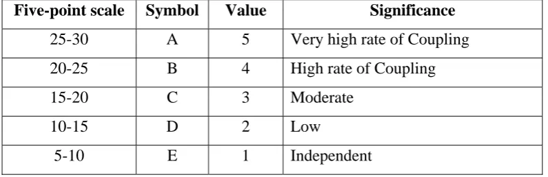
two components and is calculated using equation (1). The calculated coupling parameter is converted to five-point scale value. Components that have complicated or high volume of interactions with other components acquire a high coupling rating. Conversely those components which are independent have negative coupling rating applied. The following table shows the various coupling values between the components according to the above assumptions.
Table 1 Coupling Values
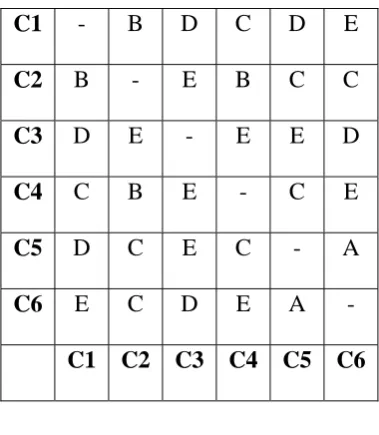
5.2 Dependency Chart
The Dependency Chart is used describe the “closeness” between the components. The chart allows capturing the interconnection information in an organized fashion. The first step is to take the various software components from the software architecture and list them in the first column of the dependency chart. The matrix to the right of that list (2nd to 6th) provides a cell for the coupling between the components that is to be calculated using equation (1). Table 2 shows a dependency chart for a software system with 6 components.
Five-point scale
Symbol
Value
Significance
25-30
A
5
Very high rate of Coupling
20-25
B
4
High rate of Coupling
15-20 C
3
Moderate
10-15 D
2
Low
C1
- B D C D E
C2
B - E B C C
C3
D E - E E D
C4
C B E - C E
C5
D C E C - A
C6
E C D E A -
C1
C2
C3
C4
C5
C6
Table 2. Sample Dependency Chart
Using this dependency chart dependency rating is calculated to select components for assembly.
This chart is used to find the coupling between the components and also to identify the proper sequence in the execution of genetic algorithm program.
5.3 Component Dependency Rating (CDR)
Component dependency rating is used to select the components for assembly in a specified sequence Genetic Algorithm. Using CDR components are chosen based on the coupling value with other components. Component dependency rating is computed for all components based on dependency chart values. This is also given as an input in Genetic Algorithm program to identify the sequence effectively. Component dependency rating of a component is calculated as the sum of the numerical values of the coupling parameter with all other components. CDR=mij
For the given dependency chart (Table 2), the CDR values are given below.
Table 3.CDR calculation for the given coupling rating in Table 2
Component Component
Coupling CDR
1 B+D+C+D+E=4+2+3+2+1+
12
2 B+E+B+C+C=4+1+4+3+3
15
3 D+E+E+E+D=2+1+1+1+2
7
4 C+B+E+C+E=3+4+1+3+1+1
13
5 D+C+E+C+A=2+3+3+3+5+3
19
6.0 Case Study for the Software Assembly Using GA
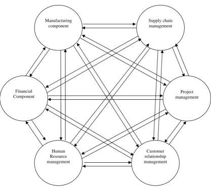
The proposed technique is applied to component based Enterprise Resource Planning (ERP) software for manufacturing application. The components were developed to check the applicability of the Genetic Algorithm. A typical ERP system will use multiple components of computer software and hardware to achieve the integration. The ERP systems (Figure 2) are designed to plan the utilization of enterprise-wide resources. The modules in an ERP include: Manufacturing, Supply chain, Financials, CRM, Human resources, Project management and Warehouse management. A key factor is the integration of data from all aspects of an organization. To accomplish this, an ERP system typically runs on a single database instance with multiple software components providing the various business functions of an organization
.
Figure 2 Sample ERP Architecture for a manufacturing application Supply chain management Manufacturing
component
Financial Component
Project management
Human Resource management
The software components include the functionalities as follows.
1. Manufacturing component(C1) include classes for Engineering, Bills of Material, Scheduling, Capacity, Workflow management, Quality control, Cost Management, Manufacturing Process, Manufacturing Projects, Manufacturing flow.
2. Supply Chain Management component(C2) consists of classes for Inventory, Order Entry, Purchasing , Product configuration, Supply chain planning, Supplier Scheduling , Inspection of goods, claim processing, Commission calculation.
3. Financial component (C3) contains classes for General Ledger, Cash Management, Accounts Payable, Accounts receivable, fixed assets.
4. Project management component (C4) includes classes for Costing, Billing, Time and Expense , Activity management
5. Human Resources management component (C5) contains classes for Human Resources , Payroll, Training, Time & Attendance, Benefits.
6. Customer relationship management component (C6) contains classes for sales and Marketing, Commissions, Service, Customer Contact and Call Center Support.
7. Data Warehouse Providing data for all the components
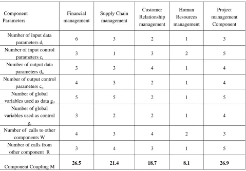
6.1 Dependency chart Construction
Component Parameters Financial management Supply Chain management Customer Relationship management Human Resources management Project management Component Number of input data
parameters di
6 3 2 1 3
Number of input control parameters ci
3 1 3 2 5
Number of output data parameters do
3 3 4 1 4
Number of output control parameters co
4 3 2 1 4
Number of global variables used as data gd
5 5 2 1 5
Number of global variables used as control
gc
3 2 2 1 4
Number of calls to other
components W 4 3 4 2 3
Number of calls from
other component R 3 4 3 1 5
Component Coupling M 26.5 21.4 18.7 8.1 26.9
Table 4 Coupling values of manufacturing component (Source: Vijayalakshmi et al.2007)
MC - D E D C C
FC C - C C C D
SCM E B - C D C
CRM B C B - A E
HRM C E C E - A
PMC C B E B C -
MC FC SCM CRM HRM PMC
Table 5 Dependency Chart for Enterprise Resource management
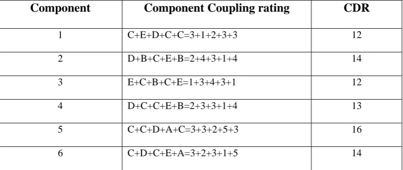
Component
Component Coupling rating
CDR
1 C+E+D+C+C=3+1+2+3+3 12
2 D+B+C+E+B=2+4+3+1+4 14
3 E+C+B+C+E=1+3+4+3+1 12
4 D+C+C+E+B=2+3+3+1+4 13
5 C+C+D+A+C=3+3+2+5+3 16
6 C+D+C+E+A=3+2+3+1+5 14
Table 6 Dependency rating for ERP
6.1Application GA to find the Assembly order
For the component assembly, it is planned to apply multiple GA for the effective assembly. In Multiple GA assembly plan, the chromosome will be coded as a string which consists of assembly sequence numbers. This comes under the permutation encoding scheme as shown below.
Chromosome: 3 2 1 4 5 6
Each number in the chromosome represents the assembly component name. In this work, the position based crossover method is used as crossover operator and shift left operator is used as mutation operator. When these genetic operators are applied in a single level GA, it is observed that the static Genetic Operator Probability Setting(GOPS) did not yield a better off springs after each generation. This motivated the author to adopt a multi-level genetic algorithm to overcome this problem.
In the application of multiple GA, Level 1 genetic algorithm is used to find the assembly sequence of the selected components. Then this result is analyzed using level 2 GA and optimizes the genetic operator probability settings to get a maximized total dependency rating.
Leve1 Genetic Algorithm:
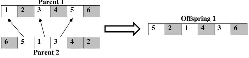
The permutation encoding scheme is adopted to code the assembly of the software component order as explained above. Level1 GA considers the Component Dependency Rating (CDR) based on the coupling between the components and it is used to evaluate the total dependency rating for each chromosome. A position based crossover is adopted and the new offspring is generated as explained in the below steps.
Step 1: Select several loci randomly from Parent 1, eg 2, 4 and 6 in Parent 1 in Figure 3.
Step 4: From the beginning of Parent 2, sequentially select the genes that have not been marked and copy into the vacancy of partial offspring 1 from the beginning.
Figure 3 Position based crossover
Further, Shift left operator is used as the mutation operator to get the new sequence and which is explained below.
The structure of the shift left operator: Chromosome << Number of Displacement
The shift left operator shifts all the bits left as per the first operand. The second operator indicates the number of bits to be shifted. The left most bit positions in the string will be inserted at the backend in sequence. Following is the example for the shift left operator
Chromosome : 1 2 3 4 5 6 Operand : String A<< 2
This operand will shift two bits of the Chromosome in the left side and left most bit positions in the string will be inserted at the backend in sequence.
Mutated String: 3 4 5 6 1 2
A roulette wheel selection scheme is adopted to form the mating pool. Genetic Operator Probability Setting for the first level GA is updated by the second level GA during the function evaluation of the second level GA. In second level GA, real coded strings of GOPS (crossover probability and mutation probability) are used as the chromosome string. The roulette wheel selection scheme is also adopted in level 2 GA. Intermediate crossover method is applied to get a new offspring in real coded string. An incremental operator is used to mutate the offspring. A static probability setting is used in the second level GA. The performance of the second level GA was tested using Himmelblau's function. Himmelblau's function is one of the well-known multimodal functions commonly used to test the optimization algorithms. The above procedure is adopted for the ERP case study and coded in the MATLAB software and found the sequence of the assembly order. The convergent plot for the
1
2 3 4 5 6
6 5 1 3 4
2
5
2 1 4 3 6
Parent 1
Parent 2
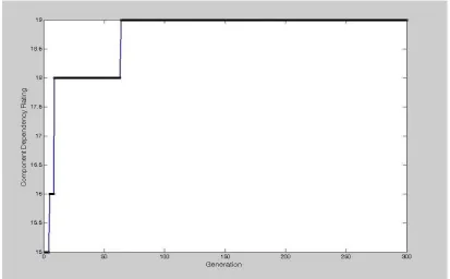
assembly sequence which is received as the result from the software is given in the figure 4. The best sequence from GA is received as 546123, which yields the total dependency rating of 19. The sequence is HRM, CRM, PMC, MC, FC then SCM.
Figure 4 Convergent Plots for the Assembly Sequence
7.0 Discussion
Experimental results show that the multi-level genetic assembly sequence planner solves component assembly problem more quickly and reliably than prior classical single-level GA approaches. This result gives a better idea for the component based assembly for large scale software systems. In the Genetic based assembly, it is possible to assemble any number of components with the consideration of dependency rating. According to the base paper (Vijayalakshmi et al, 2007) the assembly sequence are HRM, CRM, PMC, SCM, MC, and FC. But, according to the GA, assembly sequence is coming as HRM, CRM, PMC, MC, FC and then SCM. In both the methods, assembly order of the components for the first three stages is same. In the fourth stage, there is a difference between SCM and FC components.
solved more effectively than dependency based algorithm. So, the order from the fourth stage is changing and also it is believed that this assembly order is the right procedure to make the assembly sequence effectively.
8.0 Conclusion
This paper presents GA based assembly technique for the software based systems which is using large number of software components. The proposed algorithm can be applied to any number of software components and flexible for any component based software assembly. The algorithm is highly suitable for rapid development of large software systems. A simple case study for ERP system is used to illustrate the applicability of the proposed approach, and also, it can be extended to any system. The GA based software assembly is a new initiation in component assembly, and highly suitable for software industries.
References
[1] Brown, A.W. (2000) Large Scale Component based Developments, Prentice Hall PPR, ISBN-13:978-0-13-088720-7.
[2] Bucchiarone, A., Polini, A., Pelliccione, P. and Tivoli, M. (2006) ‘Towards an architectural approach for the dynamic and automatic composition of software components’, Proceedings of 2nd International Workshop on the Role of Software Architecture in Testing and Analysis (ROSATEA 2), held in conjunction with ISSTA2006, Portland, Maine, 17 July, pp.12–21.
[3] Dolbec, J. and Shepard, T. (1995) ‘A component based software reliability’, Available at: http://citeseer.ist.psu.edu/136325.html. [4] Fenton, N.E. and Fleeger, S.L.P. (1996) Software Metrics: A Rigorous and Practical Approach, International Thomson Computer
Press, ISBN 0534-95429-1.
[5] Fenton, N.E. and Neil, M. (1999) ‘A critique of software defect prediction models’, IEEE Transactions on Software Engineering, Vol. 25, No. 5, pp.675–689.
[6] Heineman, G.T. and Councill, W.T. (2001) Component-Based Software Engineering: Putting the Pieces Together, 1st edition, Boston: Addison-Wesley, ISBN 0-201-70485-4.
[7] Harry S. Delugach (2008) , ‘Formal Analysis of workflows in software development’: Handbook of research Technical Design and Social Networking Systems, (Editors: Brian Whitworth and Aldo de Moor) Information Science Reference Publ., Hershey, PA ,ISBN 978-1-60566-264-0, Chapter XX, pp. 280-297
[8] Inverardi, P. and Tivoli, M. (2003a) ‘A compositional synthesis of failure free connectors for correct component assembly’, Proceedings of 6th ICSE workshop on Component Based Software Engineering, Portland, Oregon, USA, 3–4 May.
[9] Inverardi, P. and Tivoli, M. (2003b) Software Architecture for Correct Components Assembly Chapter In Formal Methods for the Design of Computer, Communication and Software Systems: Software Architecture, Springer, Volume: LNCS 2804, September. [10] Ismail, N., Musharavati, F., Hamouda,A.S.M. and Ramli,A.R.,(2008), ‘Manufacturing process planning optimization in reconfigurable
multiple parts flow lines’,Journal of achievements in materials and manufacturing engineering, Vol.31,Issue 2, pp 671-677.
[11] Smith, S.S.F and Liu,Y.J. (2001), ‘The application of multi-level genetic algorithm in assembly planning, Journal of Industrial Technology, Vol.17,No.4,pp.1-9.
[12] Szyperski, C. (2003) Component Software: Beyond Object-Oriented Programming, 2nd edition, Addison-Wesley, ISBN-13:9780201745726.
[13] Vijayalakshmi, K., Ramaraj, N., Amuthakkannan, R. and Kannan, S.M. (2007) ‘A new algorithm in assembly for component-based software using dependency chart’, Int. J. Information Systems and Change Management, Vol. 2, No. 3, pp.261–278.