Compact Microstrip Patch Antenna with
Switchable L-Shaped Slots for Wireless
Applications
Dr.T.SHANMUGANANTHAM
*Assistant Professor, Department of Electronics Engineering School of Engineering & Technology, Pondicherry University
Pondicherry – 605 014, India
Abstract: In this paper, analysis and design of compact Microstrip patch antenna incorporated by two orthogonal L-shaped switchable slots is proposed to achieve circular polarization. Two pin diodes are inserted in to these L-shaped slots and by making these two pin diodes ON and OFF the antenna can be radiate with either right handed circular polarization or left handed circular polarization with wide bandwidth. Radiation patterns, return loss and axial ratios are presented. The antenna has an overall dimension of only 18 x 18 mm2 when printed on a substrate of dielectric constant 2.22. A rigorous experimental study has been conducted to confirm the characteristics of the antenna. The experimental results show that the designed antenna can provide excellent performance for Unlicensed & licensed WiMax (IEEE802.16a), future planetary missions and satellite link. Details of the antenna design; experimental and simulated results are presented and discussed.
Index Terms: - Reconfigurability, Microstrip, Pin diode, L-Shaped Slots.
1. INTRODUCTION
In high-performance aircraft, spacecraft, satellite, and missile applications, where size, weight, cost, performance, ease of installation, and aerodynamic profile are constraints, low-profile antennas may be required. Usually, Microstrip patch antenna merits such as simple structure, low cost, low profile, small size and high polarization [1]. Wireless communications have progressed very rapidly in recent years, many mobile units are becoming smaller and smaller [2]. At the same time the applications which require circular polarization also increased day by day [7-9]. So this reconfigurable antenna can be used in every application which requires polarization diversity [4-5]. A new design of compact broadband probe-fed patch antenna with inverted U-shaped patch and W-U-shaped ground plane design offers other advantages such as cross polarization level reduction and wider 3-dB beam width [3].In this paper, compact Microstrip patch antenna with switchable L-shaped slots for wireless applications are proposed and in this design two Pin diodes are kept in these slots. By making these two diodes ON and OFF separately this reconfigurable antenna radiates right handed circular polarization and left handed circular polarization. As LHCP and RHCP are time separated there would be no coupling between these two polarizations. The validity of this concept is demonstrated by experimental results with good parameters like return loss, radiation patterns both in LHCP and RHCP.
2. ANTENNA STRUCTURE AND DESIGN
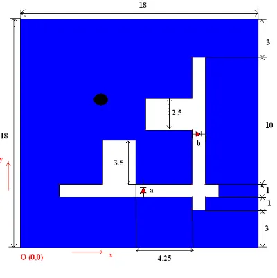
The structure of this antenna is simple and compact. The outer dimension of this antenna is just 18mm X 18 mm. The lower left corner of the antenna is assumed to be as origin O (0, 0). The two slots are incorporated as shown in fig.1. This microstrip antenna is constructed on RT /duriod 5880 substrate. The parameters of this substrate are as follows.
Substrate : RT /duriod 5880 Dielectric Constant (
r) : 2.22Fig. 1 Proposed Antenna Structure
Two L-shaped slots of width 1mm are incorporated into antenna as shown in figure 1. The two slots are having symmetric lengths. Here two PIN diodes (HPND 4005) ‘a’ and ‘b’ are placed in each slots as shown in figure at points (8.9, 4) and (13, 8.85). The diode ‘a’ is kept in such way that its positive terminal is faced to feed point. And the second diode ‘b’ is kept so that its negative terminal is faced towards the feed point (1) as shown in figure. This is to achieve ON and OFF states for both diodes for polarization diversity. Very less voltage of 2 Volts is enough for these diodes to switch between ON and OFF states. It is also worthwhile to point out that MEMS switches can be utilized here for the same functionality with a lower insertion loss. But here in IE3D simulation tool there is no facility to implement switches and diodes. So just ON diode is replaced by a short metal and OFF diode is assumed to be a open space.
The feed given here is coaxial feed with connecting radius equal to 0.5mm. The feed is given exactly at point (6.5,11.5) which is marked as black circle in figure 1. The antenna can be resonated at different points by changing the feed position on the diagonal axis. The feed point (1) comes exactly on the diagonal axis of the antenna. This is detailed information of structure of the antenna and materials used to construct it.
The photograph of this prototype antenna is shown in fig. 2 and fig. 3.
Fig. 2 Photograph of the proposed RHCP antenna
3. ANTENNA OPERATIONAL MECHANISM
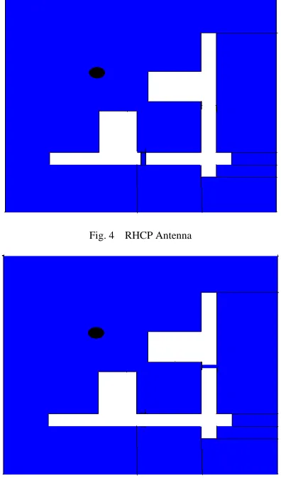
But in “Reconfigurable Patch Antenna Using Switchable L-shaped Slots for circuit Polarization Diversity” there is no need of power divider and two or three feeds. We can achieve polarization diversity with single feed itself; this is main advantage of this antenna. As this antenna is reconfigurable it as two slightly different structures. In one structure it radiates Left Handed Circular Polarization and in other form it radiates Right Handed Circular Polarization. So separate explanation is given for both RHCP and LHCP antennas clearly. Here polarization diversity is achieved by two pin diodes by making ON one diode and other OFF. When we give input voltage the diodes have different dc voltages on their two sides. If a negative voltage (such as -2 V for a HPND) is supplied, diode 1 is turned ON and second diode 2 is turned OFF and it is reversed for +ve voltage. By making diodes ‘a’ and ‘b’ ON and OFF respectively the diode radiates right handed circular polarization and when ‘a’ is OFF and ‘b’ is ON the antenna radiates left handed circular polarization. For RHCP antenna diode ‘a’ is replaced by a metal and diode ‘b’ is replaced by just an open space. For LHCP antenna diode ‘b’ is replaced by a metal and diode ‘a’ is replaced by just an open space. . The length of this metal is 1mm and width is around 0.05mm. The RHCP and LHCP antennas are shown in figs. 4 and 5 respectively.
Fig. 4 RHCP Antenna
Fig.5 LHCP Antenna
So by examining all these facts we can say that the diode ‘a’ in figure 1(also horizontal L-shaped slot) can only effect
TM
010x mode and diode ‘a’ (also vertical L-shaped slot) will only effect theTM
001x mode [6]. Therefore, the effect of the horizontal L-shaped slot on theTM
010x mode is trivial and the effect of vertical L-shaped slot onTM
001x is trivial. In RHCP antenna diode ‘a’ is made ON and diode ‘b’ is made OFF. Due to thisTM
010xslot. By this effect resonant frequency of
TM
001x mode greatly decreases. In LHCP antenna diode ‘b’ is made ON and diode ‘a’ is made OFF. Due to thisTM
001x mode electric current flow through the diode ‘b’ and at the same timeTM
010x mode current is not allowed to flow through diode ‘a’ as it is OFF. AndTM
010x mode current is forced to travel around the horizontal L-shaped slot. By this effect resonant frequency ofTM
010xmode greatly decreases. Therefore by the slots and diodes the resonant frequencies of this two modes become different. The frequency difference is controlled by the slots length, position and also switch position. If this frequency difference is properly designed, the radiation fields of the
TM
010x andTM
001x mode have the same magnitude and are90
0out of phase at a midpoint frequency. As a result, a RHCP and LHCP patterns can be obtained depending open the ON and OFF states of two switches. The antenna is simulated using IE3D software and all the parameters are obtained. The simulation results of this antenna are given in other section of this paper.4. EXPERIMENTAL RESULTS
The above proposed antenna is simulated in IE3D software tool with the same dimensions shown in fig. 1. Results are matched with standard values. Due to the symmetrical property exactly same results were obtained in both RHCP and LHCP antenna. The gain and VSWR are 6.4 dB and 1.001 for both RHCP and LHCP antenna respectively. Mainly return loss is just -30 dB in both RHCP and LHCP antenna. The simulated and measured return loss is shown in figure 6 for RHCP and LHCP. The resonating frequencies for RHCP and LHCP antennas are at 4.55 GHz. The bandwidth of this antenna in both antennas is very wide; it is around 27.5% for both antennas. Efficiency of this antenna in both shapes is 75 %.
Fig.6 Return Loss of the proposed Antenna
Fig.8 E-field Radiation patterns of LHCP Antenna
Fig.9 Measured Radiation pattern in E-plane and H plane for LHCP
The figs. 7 and 8 are
E
-right andE
-left radiation patterns of RHCP and LHCP antennas taken in polar co-ordinates. The red curve isE
-right and black curve isE
-left. We can notice that for RHCP antennaE
-left (black curve) is inside theE
-right (red curve) i.e. the gain forE
-right curve is very large when compared toE
-left curve which results in Right Handed Circular Polarization. This condition is exactly reversed in the case of LHCP antenna. For LHCP antennaE
-right (red) curve is inside theE
-left (black) curve, which tells us that the gain ofE
-left is greater thatE
-right and which results in Left Handed Circular Polarization. There is difference of around 30 dBi gain betweenE
-right andE
-left components in both RHCP and LHCP at boresight. Measured radiation pattern in E-plane and H-plane is shown in fig. 9. Figs. 10 and 11 shows axial ratios for both antennas. We can notice almost ideal axial ratio of around 0.2 dB at the boresight for both antennas.Fig.11 Axial ratio at boresight for LHCP Antenna
5. CONCLUSION
A reconfigurable patch antenna for circular polarization using switchable L-shaped slots is presented in this paper. By making two diodes in slots ON and OFF we make antenna to radiate right handed circular polarization and left handed circular polarization. With single feed polarization diversity achieved in this antenna. This antenna can be used for wireless Communication applications such as Unlicensed and Licensed WiMax (IEEE802.16), satellite communication, WLAN and space robots, in these multipath effects are the common reception problems in complex electromagnetic environments. In order to reduce signal fading caused by multipath effects, diversity techniques are usually required for the antenna. For this reason, a modified switchable L-shaped slot Microstrip antenna to achieve dual polarization diversity can be used.
References
[1] [1] Zhi Ning Chen, Michael Yan Wah Chia , "Broadband Planar Antennas: Design and Applications”, John Wiley & sons, 2006. [2] [2]K.L.Wong, “Planar Antennas for Wireless Applications,” John Wiley & sons, 2003.
[3] [3] T.Shanmuganantham, S.Raghavan, “Design of Compact Probe Fed Broadband Microstrip Patch Antenna for Wireless Applications”, AEU: International Journal of Electronics and Communications, Elsevier, Vol. 2008, 2008.
[4] [4] Xue-Xia Zhang, Fan Yang, “Study of a slit cut on a Microstrip antenna and its applications,” Microwave Opt. Technol. Lett., Vol 18, no. 4, pp.297-300, July 1998.
[5] [5] Shing-Lung Steven Yang, Student Member, IEEE, and Kwai-Man Luk, Fellow, IEEE, “ Design of a Wide-Band L-robe Patch Antenna for Pattern Reconfiguration or Diversity Applications,” IEEE Transactions on Antennas and Propagation, vol. 54, no. 2, February 2006.
[6] [6] Fan Yang, Student Member, IEEE, and Yahya Rahmat-Samii, Fellow, IEEE. “A Reconfigurable Patch Antenna Using Switchable Slots for Circular Polarization Diversity” IEEE Microwave and Wireless Components Letters, vol.12, March 2002.
[7] [7] D. K. Neog, S. S. Pattnaik, M. Dutta, S. Devi, B. Khuntia, D. C. Panda,” Inverted shaped and parasitically coupled inverted L-shaped Microstrip patch antennas for wide bandwidth”, vol.42, no.2, June 2004.
[8] [8]H.-D. Chen, J.-S. Chen, and Y.-T. Cheng, “Modified inverted-L monopole antenna for 2.4/5 GHz dual-band operations,” IEE Electron.Lett., vol. 39, no. 22, Oct. 2003.
[9] [9] R. Garg, P. Bhartia, and I. Bahl, Microstrip Antenna Design Hand book, 1st ed. Boston, MA: Artech House, pp. 794–795, 2001.
BIOGRAPHY