IJEDR1802003
International Journal of Engineering Development and Research (
www.ijedr.org
)
16
Performance prediction of Counter flow Heat
Exchanger by using CFD technique
1Shuvam Mohanty, 2Shofique Uddin Ahmed 1M.Tech Student, 2M.Tech Student
1Department of Mechanical Engineering, Amity University, Gurgaon, India
_____________________________________________________________________________________________________
Abstract— A numerical investigation of counter flow heat exchanger in a particular tube in tube heat exchanger with
reversing the flow is investigated in this paper. The investigation includes the heat transfer and the pressure drop in the heat exchanger considering water as a fluid. Many researchers have reported regarding the enhancement of counter flow heat exchangers altering the fluid temperature and using different fluids. Here to foresee the outcome of the heat exchanger in terms of temperature change and pressure drop due to variation of temperature and mass flow rate a CFD program fluent has been used. A set of CFD simulation is carried out for the double pipe counter flow heat exchanger and after validating the methodology of CFD analysis the effects are established. The experimental results available in the literature [8] are compared with CFD fluent simulation results in ANSYS 14. We have got a better comparison with the previous results with net average temperature of 323.80K using aluminum as a material of construction and viscous
k-ε model for the flow domain. However there is a very less marginal error of less than 2% comes in the simulation. The
values and the results are case responsive to the turbulence model section.
Index Terms—3D CFD modeling, RNG K-epsilon model, Temperature distribution, velocity distribution, pressure drop. _____________________________________________________________________________________________________
I.INTRODUCTION
IJEDR1802003
International Journal of Engineering Development and Research (
www.ijedr.org
)
17
different techniques. Considering two different flow configurations that is parallel and counter flow the experiments were conducted as later compared with both the flow configurations.II.COMPUTATIONAL DESIGN MODEL
Computational Fluid Dynamics, abbreviated as CFD, uses different numerical methods and a number of computerized mathematical models in order to solve and analyses problems that involve the flow of fluids. The calculations required simulating the interaction of fluids with surfaces defined by boundary conditions, and initial conditions are done by the ANSYS Fluent v14.0. The Navier stokes equations form the basis of all CFD problems. Two equation models are used for the simulations, and different models are discussed below. The continuity equation and the Navier-Stokes momentum equation govern the flow of the fluid in the counter flow heat exchanger.
Continuity equation:
𝛻. (∝𝑡𝜌𝑡𝜐𝑡𝜐𝑡) = 0
Momentum equation:
𝛻. (∝𝑡𝜌𝑡𝜐𝑡𝜐𝑡) = −∝𝑓𝛻𝑃 + 𝛻𝜏𝑓∝𝑓𝜌𝑓𝑔 + 𝐾𝑠𝑓(𝜐𝑠− 𝜐𝑓) + 𝐶𝑣𝑚∝𝑓 𝜌𝑓𝑔(𝜐𝑠𝛻𝜐𝑠− 𝜐𝑓𝛻𝜐𝑓) + 𝐶𝐿∝𝑠𝜌𝑓(𝜐𝑓− 𝜐𝑠) × (𝛻𝜐𝑓)
The energy balance equation is applied at both the hot and cold inlet.
(ṁ𝑐× 𝐶𝑝𝑐) 𝑑𝑇𝑐𝑜𝑢𝑡 𝑑𝑡 = (𝑇𝑐𝑖𝑛∗ 𝐶𝑝𝑐∗ ṁℎ) − (𝑇𝑐𝑜𝑢𝑡∗ 𝐶𝑝𝑐∗ ṁ𝑐) + (ℎ ∗ 𝐴 ∗ (𝑇ℎ𝑜𝑢𝑡− 𝑇𝑐𝑜𝑢𝑡)) (ṁℎ× 𝐶𝑝ℎ) 𝑑𝑇ℎ𝑜𝑢𝑡 𝑑𝑡 = (𝑇ℎ𝑖𝑛∗ 𝐶𝑝ℎ∗ ṁℎ) − (𝑇ℎ𝑜𝑢𝑡∗ 𝐶𝑝ℎ∗ ṁℎ) + (ℎ ∗ 𝐴 ∗ (𝑇ℎ𝑜𝑢𝑡− 𝑇𝑐𝑜𝑢𝑡)
Reynolds tensor for fluid while applying RNG 𝑘 − 𝜀 is
𝜏𝑡,𝑓 = −
2
3(𝜌𝑓𝐾𝑓+ 𝜇𝑡,𝑓𝛻𝜐𝑓)𝐼 + 𝜇𝑡,𝑓(∇𝜐𝑓+ ∇𝜐𝑓
𝑡𝑟
𝜇𝑡,𝑓= 𝜌𝑓𝐶𝜇
𝑘𝑓2
∈𝑓
With
𝐶𝜇= 0.0845
The prediction of turbulent kinetic energy and rate of dissipation obtained from the following equation;
∇. (𝛼𝑓𝜌𝑓𝑈𝑓𝜀𝑓) = ∇. (𝛼𝑓 𝜇𝑡,𝑓 𝜎𝜀 ∇𝜀𝑓) + 𝛼𝑓 𝜀𝑓 𝑘𝑓
(𝐶1𝜀𝐺𝑘,𝑓− 𝐶2𝜀𝜌𝑓𝜀𝑓) + 𝛼𝑓𝜌𝑓∏𝜀,𝑓
The RNG model constants are 𝐶𝜇 = 0.0845
𝐶1𝜀 =1.42
𝐶2𝜀= 1.68
Wall Prandtl number = 0.85 III.NUMERICAL SOLUTION
IJEDR1802003
International Journal of Engineering Development and Research (
www.ijedr.org
)
18
Fig. 1 schematic diagram of counter flow heat exchanger [8]IV.MESH GENERATION
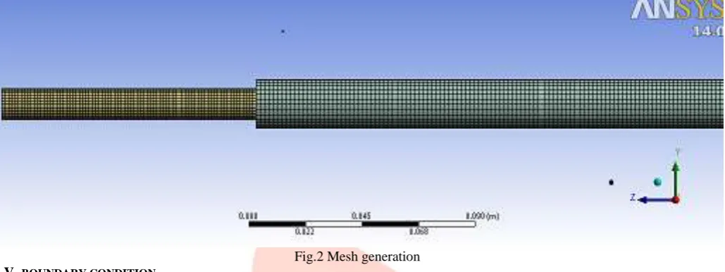
Initially a relatively coarser mesh is generated with 96833 cells. This mesh contains mixed cells (Tetra and Hexahedral cells) having both triangular and quadrilateral faces at the boundaries. Care is taken to use structured cells (Hexahedral) as much as possible, so further we switched to the medium mesh which generates 151962 cells with 139851 numbers of nodes. It is meant to reduce numerical diffusion as much as possible by structuring the mesh in a well manner, particularly near the wall region. Later on, for the mesh independent model, a fine mesh is generated with 200950 cells. For this fine mesh, the edges and regions of high temperature and pressure gradients are finely meshed. But the fine mesh lies very close to the medium mesh and considering the medium mesh the results for the temperature change comes out very good. So that’s why we go with the medium mesh.
Fig.2 Mesh generation V.BOUNDARY CONDITION
In order to simulate the conditions observed in the experiments, the fully developed parabolic velocity profile needs to be obtained before the fluid enters the tube. The parabolic velocity profile in a laminar flow and the empirical power-law equation in a turbulent flow in the channel with a circular cross-section are obtained and verified [8]. To make the inlet velocity profile to be similar as in the following literature [8], some dynamic boundary conditions are applied. Aluminum is used as a material of construction and water liquid for fluid phase. Using viscous k-ε RNG model turning the energy equation on the iterations continued.
VI.RESULTS AND DISCUSSION
IJEDR1802003
International Journal of Engineering Development and Research (
www.ijedr.org
)
19
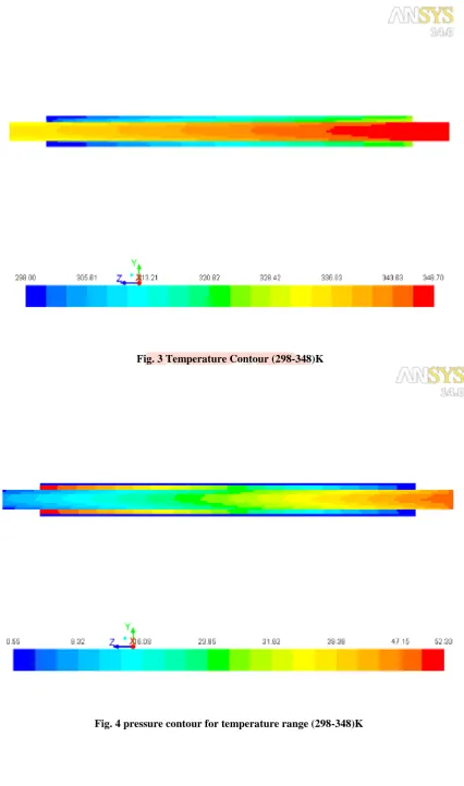
Fig. 3 Temperature Contour (298-348)KIJEDR1802003
International Journal of Engineering Development and Research (
www.ijedr.org
)
20
Fig. 5 Velocity contours for temperature (298-348)KIJEDR1802003
International Journal of Engineering Development and Research (
www.ijedr.org
)
21
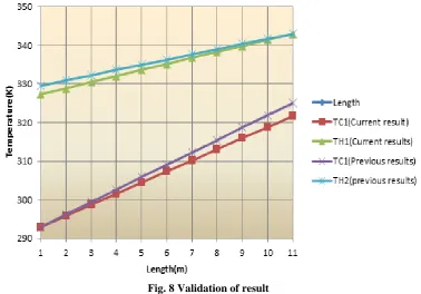
Fig. 7 Graphical representation of cold inlet temperature variationBy step changing the input temperature of cold inlet fluid and hot inlet fluid the temperature profile are studied. The results are also validated as shown in the fig.6 below. It also shows the current results are better than the following literature [8]. As the heat transfer increases the LMTD results also affects. The LMTD increases along with that heat transfer.
Fig. 8 Validation of result VII.CONCLUSION
IJEDR1802003
International Journal of Engineering Development and Research (
www.ijedr.org
)
22
could have profound effects on the performance of the counter flow heat exchanger. From the pressure and temperature contours it was found that along the outer side of the pipes the velocity and pressure values were higher in comparison to the inner values. REFERENCES[1] Mohammed, H. A., et al. "Heat transfer and fluid flow characteristics in microchannels heat exchanger using nanofluids: a review." Renewable and Sustainable Energy Reviews 15.3 (2011): 1502-1512.
[2] Kamyar, A., R. Saidur, and M. Hasanuzzaman. "Application of computational fluid dynamics (CFD) for nanofluids." International Journal of Heat and Mass Transfer 55.15-16 (2012): 4104-4115.
[3] Das, Prasanta Kumar, and Indranil Ghosh. "Thermal design of multistream plate fin heat exchangers—a state-of-the-art review." Heat Transfer Engineering 33.4-5 (2012): 284-300.
[4] Raj, R. Thundil Karuppa, et al. "Experimental and numerical analysis using CFD technique of the performance of the absorber tube of a solar parabolic trough collector with and without insertion." Energy Efficient Technologies for Sustainability (ICEETS), 2013 International Conference on. IEEE, 2013.
[5] Mohanty, Rajiva Lochan, Sharon Bashyam, and Darpahari Das. "Numerical analysis of double pipe heat exchanger using heat transfer augmentation techniques." International Journal of Plastics Technology 18.3 (2014): 337-348.
[6] Raj, R. Thundil Karuppa, et al. "Numerical analysis of helically coiled heat exchanger using cfd
technique." ARPNJEAS 9.3 (2014): 300-307.
[7] Aneesh, A. M., et al. "Thermal-hydraulic characteristics and performance of 3D straight channel based printed circuit heat exchanger." Applied Thermal Engineering 98 (2016): 474-482.
[8] Nagarsheth, Shaival H., Dhruvi S. Bhatt, and Jayesh J. Barve. "Temperature profile modelling, simulation and validation for a counter flow water tube in tube heat exchanger." Control Conference (ICC), 2017 Indian. IEEE, 2017.
[9] Peigné, Pierre, Christian Inard, and Lionel Druette. "Ventilation heat recovery from wood-burning domestic flues. A Theoretical Analysis Based on a Triple Concentric Tube Heat Exchanger." Energies 6.1 (2013): 351-373.