*Corresponding author: [email protected] 2017 UTHM Publisher. All right reserved.
penerbit.uthm.edu.my/ojs/index.php/jst
The Determination of Laser Spot Size of an Optical Tweezers by Stuck
Bead Method
Muhamad Safuan Mat Yeng, Shahrul Kadri Ayop* and Muhammad Yunus Hamid
Department of Physics, Faculty of Science and Mathematics, Universiti Pendidikan Sultan Idris, 35900 Tanjong Malim, Perak.
Received 30 September 2017; accepted 30 November 2017; available online 26 December 2017
1. Introduction
Laser technology has undergone revolution from time to time. Many instruments use lasers as the core component for various applications. The advance of laser manipulation technology has enabled the development of many devices for example optical tweezers and optical spectroscopy. Lasers can be operated in various modes. The basic mode is the single Gaussian beam profile which is widely chosen for its profile has better in coherence, power and directionality [1] . Gaussian beam profile shows a bell shape line when the laser intensity is plotted along the lateral axis of the beam [2].
The most basic parameter needs to be considered when handling laser instrument is the laser beam waist, . There are several suggested methods to determine such as boundary-diffraction wave [4], knife-edge method, burn spot [5], opaque ribbon [1], slit method and, pinhole method. The knife edge method (KEM) is one of the traditional method being applied for beam waist measurement due to cheap and quick procedures [6]. KEM requires error function fitting to the observed intensity profile to get the beam waist. The experimental data of power of laser beam used across scanning the knife edge is recorded and fitted with equation
(1)
The parameter represents power transmitted passed the knife, represents detected power offset, is maximum measurable power, is complimentary error function, is position shift and is beam waist.
However, the beam waist definition was not standardized. Some researcher define the beam waist is the distance of the laser drop power from 10% to 90% of its full power [7] [8]. In another study, the beam waist is measured at distance where the laser power drop to [9] and also [10] from the maximum power.
In this study, an alternative method to determine laser spot size is proposed using stuck bead method (SBM). This is referred as laser beam waist at the focal point of an objective. For an optical tweezers, of interest is the laser spot size at the focal plane of an objective. This will affect the spatial distribution of the optically trapped particle [3]. The SBM is generally used in the signal-to-displacement calibration of QPD in optical tweezers applications [11]. Thus, SBM will greatly reduce experimental time because it can be used in both laser spot size determination and QPD calibration. Obtained Abstract: The determination of laser spot size is one of an essential requirement in a laser system. This study proposed an alternative method to determine the laser spot size by using stuck bead method (SBM). 3 µm polystyrene bead stuck at glass slide was used to scan laser spot in an optical tweezers setup. This was compared with beam waist measurement using Knife Edge Method. In both methods, quadrant photo-diode (QPD) was used to collected position dependent intensity profiles at three applied laser powers (95 mW, 122 mW and 150 mW) of 915 nm wavelength. Even though there is still no standard definition of beam waist, the using SBM is suggested as the alternative definition of beam spot in optical tweezers application.
71 values using SBM are compared with values
using KEM.
2. Experimental Setup
Optical System
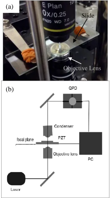
An optical tweezers was set-up as illustrated in the Fig. 1. An infrared laser beam with 915 nm wavelength was emitted from laser diode and coupled through fiber coupler. The laser beam passed through beam expander and polarizer. The laser beam was reflected by dichroic mirror into the objective lens (100× NA 1.25 WD 0.25 mm, oil immersion type)
and focused at a sample on
nanopositioner stage. Then the scattered laser was collected by condenser lens (10× NA 0.25 WD 7.0 mm, air type) and deflected by dichroic mirror toward the QPD (PDQ80A, Thorlabs). The QPD detects the change in laser intensity due to the movement of the sample. This signal was recorded and the signal was transferred to PC for post-analysis. The experimental process was observed by a CCD camera installed behind the objective.
Fig. 1 (a) The experimental setup for SBM
method and (b) schematic diagram of optical tweezers setup.
Knife-Edge Method (KEM)
Fig. 2 shows the plan view of measurement using KEM. A knife blade (1.7 mm × 5.7 mm) was placed at the focal plane of the objective. The function of knife blade was to block the laser. When the laser was switched on, the knife was moved along one direction until totally blocking the beam. The passed laser was detected by QPD at every move position. The laser power was set at 95 mW, 122 mW and 150 mW.
Fig. 2 (a) The experimental setup for KEM
method and (b) the motion of knife-edge along - direction blocking the laser spot (plan view).
Stuck Bead Method (SBM)
This method used a microbead stuck at glass slide to scan across the laser beam spot. The used bead was 3 m in diameter of polystyrene type (Polysciences, Inc). A drop of bead solution was diluted with 2 ml of deionized water. The solution was then dropped on glass slide and covered with cover slip with a space made by double sided tape. The sample was then left for 2 hour for the bead to stick at the wall of the glass. The sample was then placed at the focal plane of the objective. One can verify the stuck bead when it was not affected by optical trap force when the optical tweezers is operated.
(b) (a)
Objective Lens Knife
(a)
(b)
Slide
72 Fig. 3 visualizes the SBM process. The
stuck bead was moved by nanopositioner stage along one direction from point a to g. The scattered laser due to the disturbance of the bead was collected by the QPD and transferred to PC for post analysis. The laser power was set to 95 mW, 122 mW and 150 mW for every set of stuck bead data.
Fig. 3 (a) 3µm stuck bead image taken from
CCD camera (b) The motion of stuck bead over the laser spot at the focal plane (plan view).
3. Results and Discussion
The QPD is able to detect sum and differential signal of light upon its sensing element. In this study, the sum signal was the most useful to evaluate . Fig. 4 shows the sum signal of QPD versus knife position using KEM for three laser powers, 95 mW, 122 mW and 150 mW as measured at the position before the objective.
Fig. 4 The sum signal of QPD versus knife
position for KEM.
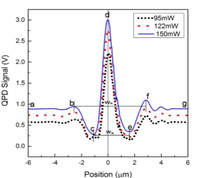
The SUM signal in -direction for SBM is illustrated in Fig. 5 for used laser power 92 mW, 122 mW and 150 mW. The spot size was scanned by the stuck bead in one direction. All the curves show similar profile. The relative position refers to the center of the spot where the intensity peak is detected. This corresponds to point d in Fig. 3. At this point, the bead acted like a lens where incoming beam was being focused and intensified on the QPD. At point a and g, the bead did not effectively cross the spot. When the bead was at point b, the beam started to be disturbed. A substantial amount of light reflected toward the QPD. The same explanation applied to point f. At point c and e, the beam diverted the beam away from central axis. Therefore, the detected intensity dropped.
(a) 3µm
Stuck bead
73
Fig. 5 Sum signal in -direction using SBM.
Four definition of measuring was performed in the data collected using KEM: (i) 10%-90% : the distance from the 10% of drop to 90% drop from the maximum measured power
(ii) : the distance from the maximum power to (63%) drop.
(iii) : the distance from the maximum power to (86%) drop.
(iv) : the width fitting from Eq. 1.
The fitting is shown in Fig. 4
The intensity profiles are independent of used laser power. Average was obtained from these three powers. These results are tabulated in Table 1.
Table 1 Comparison of between KEM and
SBM.
Method Beam Waist,
(µm)
KEM 10%-90% 2.75 ± 0.02
3.34 ± 0.02
4.41 ± 0.01
3.75 ± 0.02
SBM A 5.45 ± 0.02
B 2.72 ± 0.01
Two range of interested can be figured out from the measurement using SBM, and . is the distance between point b and f while is the distance between point c and e. The results were compared to KEM method in Table 1.
The comparable pair of spot size are
10%-90% and B. These were the smallest defined spot sizes. While A was the largest defined spot sizes. The error function fitting resulted in values between and . For the purpose of beam spot size in optical tweezers, was suggested for the best definition. It is because, these waist covers the area of effective optical trap where the optically trapped bead can produce detectable change in QPD signal.
4. Conclusion
This study proposed an alternative way to measure laser spot size by using stuck bead method (SBM). Beam waist measurement result by SBM was compared to common knife edge method (KEM). Even though there is still no standard definition of beam waist, the using SBM is suggested as the alternative definition of beam spot in optical tweezers application.
Acknowledgements
The first author would like to acknowledge the support from MyBrainSc program. This study was supported under FGRS 2017-0076-101-02 program. Both are provided by Malaysia Ministry of Higher Education.
References
[1] A. Yoshida, “A simple technique for quickly measuring the spot size of Gaussian laser beams,” Opt. Laser Technol., no. December, pp. 273–274, 1976.
[2] H. M. Shapiro, “Laser beam shaping and spot size.,” Curr. Protoc. Cytom., vol. Chapter 1, p. Unit 1.6, 2001. [3] M. Y. Hamid, S. K. Ayop, W. N. S.
74 1–8, 2016.
[4] S. Kimura and C. Munakata, “Method for measuring the spot size of a laser beam using a boundary-diffraction wave.,” Opt. Lett., vol. 12, no. 8, pp. 552–4, 1987.
[5] Y. C. Kiang and R. W. Lang, “Measuring focused Gaussian beam spot sizes: a practical method.,” Appl. Opt., vol. 22, no. 9, p. 1296, 1983. [6] J. Magnes, D. Odera, J. Hartke, M.
Fountain, L. Florence, and V. Davis, “Quantitative and Qualitative Study of Gaussian Beam Visualization Techniques,” J. Opt., no. 2, pp. 1–5, 2006.
[7] J. Trägårdh et al., “A simple but precise method for quantitative measurement of the quality of the laser focus in a scanning optical microscope,” J. Microsc., vol. 259, no. 1, pp. 66–73, 2015.
[8] A. E. Siegman, “Choice of clip levels for beam width measurements using knife-edge techniques,” IEEE J. Quantum Electron., vol. 27, no. 4, pp. 1098–1104, 1991.
[9] M. A. de Araújo, R. Silva, E. de Lima, D. P. Pereira, and P. C. de Oliveira, “Measurement of Gaussian laser beam radius using the knife-edge technique: improvement on data analysis,” Appl. Opt., vol. 48, no. 2, p. 393, 2009. [10] J. Blazej, “The measurement of a
transverse profile of laser beam by Knife Edge method,”no. 1, pp. 3–8. [11] K. C. Neuman and S. M. Block,