TB Wood’s • 888-829-6637 P-5020-TBW Form 1445 1
G-Flex Coupling
Service & Installation Instructions
P-5020-TBWGeneral Guidance for the installation of TB Wood’s grid couplings
General Guidance for the installation of TB Wood’s grid couplings
1. MOUNT SEALS AND HUBS 1000T10 (horizontally split cover): Light-ly smear seals with grease and place on shafts before mounting hubs.
1000T20 (vertically split cover): Vertical covers are NOT axially split and MUST be placed over shaft before fitting hubs. Check to verify that half covers have been placed correctly on shafts. Mount hubs, usually with the hub face flush with shaft end. Where supplied, tighten set screws.
2. ALIGNMENT
Satisfactory alignment can be achieved with the use of a straight edge and feeler gauge, although a dial indicator would generally improve accuracy.
3. GAP AND ANGULAR ALIGNMENT Set gap using a spacer bar equal in thick -ness to the hub gap specified in the table on back page. With the spacer bar in -serted to the same radial depth, measure clearance between bar and hub face at 90° intervals using feelers.
4. PARALLEL OFFSET ALIGNMENT Use a straight edge and feelers, or dial indicator, over the tops of the coupling teeth,taking measurements at 90° inter -vals. Error should not exceed offset limit specified in the table on back page.
5. TIGHTEN ALL EQUIPMENT BASED MOUNTING FASTENERS. REPEAT STEPS 3 & 4 AND IF NECESSARY RE-ALIGN
6. GRID ASSEMBLY
1000T20 (vertically split cover), insert gasket through the gap and support on either hub or shaft. Before inserting the grid segments, thoroughly pack the grooves with NGLI #2 lubricant. A list of recommended lubricants can be found on the back page.
When grids are supplied in two or more segments assemble so the cut ends at a segment joint extend in the same direc -tion. Spread the grid slightly so that it will pass over the coupling teeth, and tap all the rungs into the respective slots with a soft mallet.
7. COVER ASSEMBLY
Pack the spaces around the grid with lu -bricant and wipe off the excess flush with top of grid.
1000T10 (horizontally split cover): Posi-tion seals on hubs so that they line up with grooves on cover. Position gaskets on low -er cov-er half and assemble cov-ers so that match marks are on the same side. If us -ing the coupl-ing in any position other than horizontal, assemble cover halves with the lug and match mark up, or on the high side. Fasten the cover halves to the torque specified in the table on back page.
Series 1000T20 (vertically split cover):
Remove lube plugs to ease cover assem
-bly. Slide cover halves, complete with seal, onto hubs. Position lube holes at 180° apart. Align cover and gasket bolt holes and fasten flanges together using the bolts provided, tightening to the torque speci -fied in the table on back page.
MAINTENANCE
Check coupling misalignment every year and adjust if required. Excessive misalign -ment, high ambient temperatures and/or frequent rapid reversing may necessitate more frequent inspections.
If quantity of lubricant appears low, check for leaks and change seals. If necessary, replenish lubricant.
Clean coupling of all old lubricant and re -place annually.
1. MOUNT SEALS AND HUBS
1000T10 (horizontally split cover): Lightly smear seals with grease and place on shafts before mounting hubs.
1000T20 (vertically split cover): Vertical covers are NOT axially split and MUST be placed over shaft before fitting hubs. Check to verify that half covers have been placed correctly on shafts. Mount hubs, usually with the hub face flush with shaft end. Where supplied, tighten set screws.
2. ALIGNMENT
Satisfactory alignment can be achieved with the use of a straight edge and feeler gauge, although a dial indicator would generally improve accuracy.
3. GAP AND ANGULAR ALIGNMENT
Set gap using a spacer bar equal in
thickness to the hub gap specified in the table on page 4. With the spacer bar inserted to the same radial depth, measure clearance between bar and hub face at 90° intervals using feelers.
4. PARALLEL OFFSET ALIGNMENT
Use a straight edge and feelers, or dial indicator, over the tops of the coupling teeth,taking measurements at 90°
intervals. Error should not exceed offset limit specified in the table on page 4.
TB Wood’s • 888-829-6637 P-5020-TBW Form 1445 3
General Guidance for the installation of TB Wood’s grid couplings
1. MOUNT SEALS AND HUBS 1000T10 (horizontally split cover): Light-ly smear seals with grease and place on shafts before mounting hubs.
1000T20 (vertically split cover): Vertical covers are NOT axially split and MUST be placed over shaft before fitting hubs. Check to verify that half covers have been placed correctly on shafts. Mount hubs, usually with the hub face flush with shaft end. Where supplied, tighten set screws.
2. ALIGNMENT
Satisfactory alignment can be achieved with the use of a straight edge and feeler gauge, although a dial indicator would generally improve accuracy.
3. GAP AND ANGULAR ALIGNMENT Set gap using a spacer bar equal in thick -ness to the hub gap specified in the table on back page. With the spacer bar in -serted to the same radial depth, measure clearance between bar and hub face at 90° intervals using feelers.
4. PARALLEL OFFSET ALIGNMENT Use a straight edge and feelers, or dial indicator, over the tops of the coupling teeth,taking measurements at 90° inter -vals. Error should not exceed offset limit specified in the table on back page.
5. TIGHTEN ALL EQUIPMENT BASED MOUNTING FASTENERS. REPEAT STEPS 3 & 4 AND IF NECESSARY RE-ALIGN
6. GRID ASSEMBLY
1000T20 (vertically split cover), insert gasket through the gap and support on either hub or shaft. Before inserting the grid segments, thoroughly pack the grooves with NGLI #2 lubricant. A list of recommended lubricants can be found on the back page.
When grids are supplied in two or more segments assemble so the cut ends at a segment joint extend in the same direc -tion. Spread the grid slightly so that it will pass over the coupling teeth, and tap all the rungs into the respective slots with a soft mallet.
7. COVER ASSEMBLY
Pack the spaces around the grid with lu -bricant and wipe off the excess flush with top of grid.
1000T10 (horizontally split cover): Posi-tion seals on hubs so that they line up with grooves on cover. Position gaskets on low -er cov-er half and assemble cov-ers so that match marks are on the same side. If us -ing the coupl-ing in any position other than horizontal, assemble cover halves with the lug and match mark up, or on the high side. Fasten the cover halves to the torque specified in the table on back page.
Series 1000T20 (vertically split cover):
Remove lube plugs to ease cover assem
-bly. Slide cover halves, complete with seal, onto hubs. Position lube holes at 180° apart. Align cover and gasket bolt holes and fasten flanges together using the bolts provided, tightening to the torque speci -fied in the table on back page.
MAINTENANCE
Check coupling misalignment every year and adjust if required. Excessive misalign -ment, high ambient temperatures and/or frequent rapid reversing may necessitate more frequent inspections.
If quantity of lubricant appears low, check for leaks and change seals. If necessary, replenish lubricant.
Clean coupling of all old lubricant and re -place annually.
5. TIGHTEN ALL EQUIPMENT BASED MOUNTING FASTENERS. REPEAT STEPS 3 & 4 AND IF NECESSARY RE-ALIGN
6. GRID ASSEMBLY
1000T20 (vertically split cover), insert gasket through the gap and support on either hub or shaft. Before inserting the grid segments, thoroughly pack the grooves with NGLI #2 lubricant. A list of recommended lubricants can be found on the page 4.
When grids are supplied in two or more segments assemble so the cut ends at a segment joint extend in the same
direction. Spread the grid slightly so that it will pass over the coupling teeth, and tap all the rungs into the respective slots with a soft mallet.
7. COVER ASSEMBLY
Pack the spaces around the grid with lubricant and wipe off the excess flush with top of grid.
1000T10 (horizontally split cover):
Position seals on hubs so that they line up with grooves on cover. Position gaskets on lower cover half and assemble covers so that
match marks are on the same side. If using the coupling in any position other than horizontal, assemble cover halves with the lug and match mark up, or on the high side. Fasten the cover halves to the torque specified in the table on page 4.
Series 1000T20 (vertically split cover): Remove lube plugs to ease cover assembly. Slide cover halves, complete with
seal, onto hubs. Position lube holes at 180° apart. Align cover and gasket bolt holes and fasten flanges together using the bolts provided, tightening to the torque specified in the table on page 4.
MAINTENANCE
Check coupling misalignment every year and adjust if required. Excessive
misalignment, high ambient temperatures and/or frequent rapid reversing may necessitate more frequent inspections.
If quantity of lubricant appears low, check for leaks and change seals. If necessary, replenish lubricant.
4 TB Wood’s • 888-829-6637 P-5020-TBW Form 1445
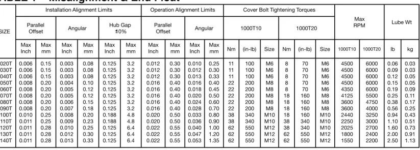
TABLE 1 – Misalignment & End Float
SIZEInstallation Alignment Limits Operation Alignment Limits Cover Bolt Tightening Torques
Max
RPM Lube Wt
Parallel
Offset Angular Hub Gap 10% ParallelOffset Angular 1000T10 1000T20
Max
Inch Maxmm Max Inch Maxmm Max Inch Maxmm Max Inch Maxmm Max Inch Maxmm Nm (in-lb) Size Nm (in-lb) Size 1000T10 1000T20 lb kg
1020T 1030T 1040T 1050T 1060T 1070T 1080T 1090T 1100T 1110T 1120T 1130T 1140T 0.006 0.006 0.006 0.008 0.008 0.008 0.008 0.008 0.010 0.011 0.011 0.011 0.011 0.15 0.15 0.15 0.20 0.20 0.20 0.20 0.20 0.25 0.25 0.28 0.28 0.28 0.003 0.003 0.003 0.004 0.005 0.005 0.006 0.007 0.008 0.009 0.010 0.012 0.013 0.08 0.08 0.08 0.10 0.12 0.12 0.15 0.18 0.20 0.23 0.25 0.30 0.33 0.125 0.125 0.125 0.125 0.125 0.125 0.125 0.125 0.188 0.188 0.125 0.125 0.125 3.2 3.2 3.2 3.2 3.2 3.2 3.2 3.2 4.8 4.8 6.4 6.4 6.4 0.012 0.012 0.012 0.016 0.016 0.016 0.016 0.016 0.020 0.020 0.022 0.022 0.022 0.30 0.30 0.30 0.40 0.40 0.40 0.40 0.40 0.50 0.50 0.55 0.55 0.55 0.010 0.012 0.013 0.016 0.018 0.020 0.024 0.028 0.033 0.036 0.040 0.047 0.053 0.25 0.30 0.33 0.40 0.45 0.50 0.60 0.70 0.80 0.90 1.00 1.20 1.35 11 11 11 22 22 22 22 22 38 38 62 62 62 100 100 100 200 200 200 200 200 340 340 550 550 550 M6 M6 M6 M8 M8 M8 M8 M8 M10 M10 M12 M12 M12 8 8 8 8 8 18 18 18 18 38 38 62 62 70 70 70 70 70 160 160 160 160 340 340 550 550 M6 M6 M6 M6 M6 M8 M8 M8 M10 M10 M10 M12 M12 4500 4500 4500 4500 4350 4125 3600 3600 2440 2250 2025 1800 1550 6000 6000 6000 6000 6000 5500 4750 4000 3250 3000 2700 2400 2200 0.06 0.09 0.12 0.15 0.19 0.25 0.38 0.56 0.94 1.10 1.60 2.00 2.50 0.03 0.03 0.05 0.05 0.09 0.11 0.17 0.25 0.43 0.51 0.73 0.91 1.13 MANUFACTURER PRODUCT
American Lubricants Co.
(Dayton, OH) Alubco Bison 1650
Brooks Technology (Cleveland, OH) (Fuchs Lubricants)
Superplex EP #1 or Benalene 350 EP #2 Chevron Lubricants Coupling Greaseor Duralith EP2 Citgo Petroleum Corp. Premium Lithium EP2
Exxon / Mobil Corp. Mobilux EP111 Fiske Bros. Refining Co. Lubriplate 630AA
Anderol Inc.
(Houghton, Canada) Anderol 786
Kendall Motor Oil L-424
Lyondell Lubricants
(Houston, TX) Litholene H EP 2
Maryn International/ Power Up Lubricants
(Calgary, Canada)
Thixogrease EP #2 Pennzoil / Quaker State or Pennlith EP712Pennlith EP711 Syn-Tech Ltd. (Addison, IL) NS-2913-G1
Texaco Inc. or Texaco Coupling GreaseMulifax EP2 UNOCAL 76
(TOSCO Corporation) UNOBA EP2
TABLE 2 – LUBRICANTS
TB Wood’s
G-Flex Coupling
Installation Instructions
TB Wood’s Incorporated
440 North Fifth Avenue • Chambersburg, PA 17201 Tel: 888-TBWOODS • 717-264-7161
-+
www.tbwoods.com
2000 Clovis Barker Road San Marcos, TX 78666 512-353-4000
Altra Industrial Motion
All Customer Service phone numbers shown in bold
For information concerning our sales offices in Asia Pacific check our website www.altramotion.com.cn
Linear Products
Warner Linear
Linear Actuators
New Hartford, CT - USA 1-800-825-6544 For application assistance: 1-800-825-9050
Saint Barthélémy d’Anjou, France
+33 (0)2 41 21 24 24 Overrunning Clutches
Formsprag Clutch
Overrunning Clutches and Holdbacks
Warren, MI - USA 1-800-348-0881– Press #1
For application assistance: 1-800-348-0881 – Press #2
Marland Clutch
Roller Ramp and Sprag Type Overrunning Clutches and Backstops
Warren, MI - USA 1-800-216-3515
Stieber Clutch
Overrunning Clutches and Holdbacks
Heidelberg, Germany +49 (0) 6221-30470 Belted Drives and Sheaves
TB Wood’s
Belted Drives
Chambersburg, PA - USA 1-888-829-6637– Press #5
For application assistance: 1-888-829-6637 – Press #7 Couplings
Ameridrives
Mill Spindles, Ameriflex, Ameridisc
Erie, PA - USA 1-814-480-5000
Gear Couplings
San Marcos, TX - USA 1 -800-458-0887
Universal Joints, Drive Shafts, Mill Gear Couplings
Erie, PA - USA 1-920-593-2444
Bibby Turboflex
Disc, Gear, Grid Couplings, Overload Clutches
Dewsbury, England +44 (0) 1924 460801 Boksburg, South Africa +27(0) 11 918 4270
Guardian Couplings
Engineered Flywheel Couplings, Engine Housings and Pump Mounts, Flexible Shaft Couplings
Michigan City, IN - USA 1-219-874-5248
Huco
Precision Couplings and Air Motors
Hertford, England +44 (0) 1992 501900 Chambersburg, PA - USA 1-888-829-6637
Lamiflex Couplings
Flexible Couplings, Bearing Isolators, and Coupling Guards
Cotia, SP - Brasil +55 (11) 4615-6300
Couplings Cont.
TB Wood’s
Elastomeric Couplings
Chambersburg, PA - USA 1-888-829-6637– Press #5
For application assistance: 1-888-829-6637 – Press #7
General Purpose Disc Couplings
San Marcos, TX - USA 1-888-449-9439 Electromagnetic Clutches and Brakes
Inertia Dynamics
Spring Set Brakes; Power On and Wrap Spring Clutch/Brakes
New Hartford, CT - USA 1-800-800-6445
Matrix
Electromagnetic Clutches and Brakes, Pressure Operated Clutches and Brakes
Brechin, Scotland +44 (0) 1356 602000 New Hartford, CT - USA 1-800-825-6544
Warner Electric
Electromagnetic Clutches and Brakes
New Hartford, CT - USA 1-800-825-6544 For application assistance: 1-800-825-9050
Saint Barthélémy d’Anjou, France +33 (0)2 41 21 24 24
Precision Electric Coils and Electromagnetic Clutches and Brakes
Columbia City, IN - USA 1-260-244-6183 Engineered Bearing Assemblies
Kilian
Engineered Bearing Assemblies
Syracuse, NY - USA 1-315-432-0700
Gearing
Bauer Gear Motor
Geared Motors
Esslingen, Germany +49 (711) 3518-0 Middlesex, NJ - USA 1-732-469-8770
Boston Gear
Enclosed and Open Gearing, Electrical and Mechanical P.T. Components
Charlotte, NC - USA 1-800-825-6544 For application assistance: 1-800-816-5608
Nuttall Gear and Delroyd Worm Gear
Worm Gear and Helical Speed Reducers
Niagara Falls, NY - USA 1-716-298-4100 Heavy Duty Clutches and Brakes
Industrial Clutch
Pneumatic and Oil Immersed Clutches and Brakes
Waukesha, WI - USA 1-262-547-3357
Svendborg Brakes
Industrial Brakes and Brake Systems
Vejstrup, Denmark +45 63 255 255
Twiflex
Caliper Brakes and Thrusters
Wichita Falls, TX - USA 1-844-723-3483 Twickenham, England +44 (0) 20 8894 1161
Wichita Clutch
Pneumatic Clutches and Brakes
Wichita Falls, TX - USA 1-800-964-3262 Bedford, England +44 (0) 1234 350311