PV and the Electrical Code
This course was prepared by the
Canadian Solar Industries Association (CanSIA) 2378 Holly Lane, Suite 208
Ottawa, Ontario K1V 7P1 Tel: (613) 736-9077 FAX: (613) 736-8938 Email: [email protected]
www.cansia.ca
Authors: Charles R. Price
Eric Smiley
with funding assistance provided by Natural Resources Canada
Renewable and Electrical Energy Division
Canadian Solar Industries Association 2004 Version 1.2
Notice to the Reader
Publisher and authors do not warrant or guarantee any of the products described herein or perform any independent analysis in connection with any of the product information contained herein. Publisher and authors do not assume and expressly disclaims any obligation to obtain and include information other than that provided to it by the manufacturer.
The reader is expressly warned to co nsider and adopt all safety precautions that might be indicated by the activities described herein and to avoid all potential hazards. By following the instructions contained herein, the reader willingly assumes all risks in connection with such instruction.
The publisher and authors maks no representation or warranties of any kind, including but not limited to, the warranties of fitness for particular purposes or merchantability, nor are any such representations implied with respect to the material set forth herein, and the publisher and authors take no responsibility with respect to such material. The publisher and authors shall not be liable for any special, consequential or exemplary damages resulting, in whole or in part, from the readers’ use of, or reliance upon this material.
PV and the Electrical Code
Table of Contents
1. INTRODUCTION 6
2. THE OBJECT OF THE CEC SECTION 2 AND GENERAL INFORMATION 7
2.1 The Layout of the CEC Book 7
2.2 The Object of the CEC 8
2.2.1 Rule 2-004: Permits 8
2.2.2 Rule 2-006: Application for Inspection 8
2.2.3 Rule 2-24: Use of Approved Equipment 9
2.2.4 Rule 2-308: Working Space About Electrical Equipment 10
3. CEC SECTION 50 – SOLAR PHOTOVOLTAIC SYSTEMS 11
3.1 Scope 11
3.2 Terminology 12
3.3 Marking 13
3.4 Voltage Rating 14
3.5 Current Rating 15
3.6 Overcurrent Protection 18
3.7 Disconnecting Means 18
3.8 Wiring 19
3.9 Module Interconnection 20
3.10 Interconnected systems 21
4. CEC SECTION 4 – CONDUCTORS 23
4.1 Scope 23
4.2 Ampacity of Wires and Cable 23
4.3 Insulated Conductors 25
4.4 Flexible Cord 25
4.5 Colour of Conductors 26
5. CEC SECTION 6 – SERVICES AND SERVICE EQUIPMENT 27
5.1 Scope 27
5.2 Overhead Conductors 27
5.3 Terminating Conductors 28
5.4 Consumer’s Service Equipment Location 28
6. CEC SECTION 8 – CIRCUIT LOAD AND DEMAND FACTORS 30
6.1 Scope 30
6.2 Conductor Selection on the basis of Current Carrying Capacity 30 6.3 Voltages to be used when determining conductor current ratings 30 6.4 Conductor Selection on the basis of Voltage Drop 31
6.5 Maximum Circuit Loading 34
7. CEC SECTION 10 – GROUNDING AND BONDING 37
7.1 Grounding 38
7.1.1 The DC Section 38
7.1.2 The AC Section 40
7.2 Bonding 41
7.2.1 Bonding Methods 41
7.3 Grounding Electrodes 42
7.4 Lightning Arrestors 42
8. SECTION 12 – WIRING METHODS 44
8.1 Scope 44
8.2 Underground Installations 44
8.3 Conductors in Parallel 44
8.4 Types of Conductors 46
8.5 Exposed Wiring 46
8.6 Non-metallic sheathed cable 46
8.7 Armoured Cable 47
8.8 Raceways 47
9. CEC SECTION 14 – PROTECTION AND CONTROL 48
9.1 Scope 48
9.2 AC and DC Ratings 50
9.2.1 Wires 50
9.2.2 Fuses and Circuit Breakers 51
9.2.3 Switches 51
10. CEC SECTION 18 – HAZARDOUS LOCATION 54
10.1 Location Classes 54
10.2 Installations in Hazardous Locations 54
10.3 Equipment Approved for use in Hazardous Locations 55 10.3.1 Installing Equipment Outside The Classified Area 56
10.3.2 Intrinsically Safe Equipment 56
11. CEC SECTION 26 – INSTALLATION OF ELECTRICAL EQUIPMENT 58
11.1 Storage Batteries 58
11.1.1 Battery Ventilation 59
11.2 Receptacle Configurations 61
Table of Figures
Figure 1: Diagram for Identifying PV System Components ... 13
Figure 2: Label for Solar Photovoltaic System... 14
Figure 3 Placement of Disconnect means in a Stand-alone PV System... 19
Figure 4 Arrangement of Bonding and Negative Conductors in a Grounded System ... 21
Figure 5: Rain-tight service head, indicating drip loops and attachment... 28
Figure 6 Battery State of Charge... 31
Figure 7 Maximum Allowable Voltage Drop in Circuits ... 32
Figure 8: Drawing of typical PV System with Bonding Conductors... 38
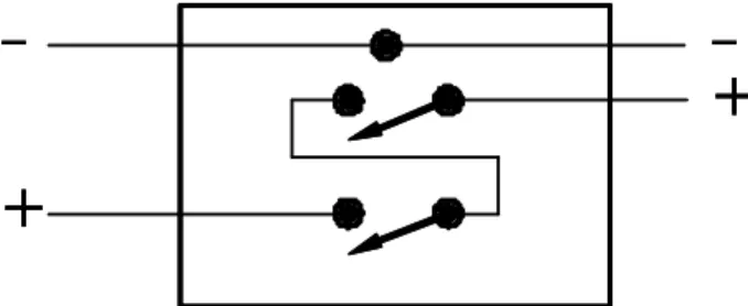
Figure 9 Double Pole Switch used for a DC Disconnect in a Grounded System... 51
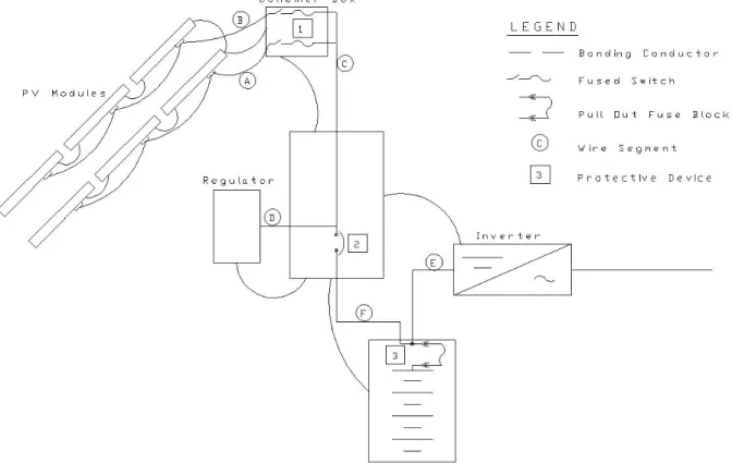
Figure 10 The DC Portion of a Typical PV System... 52
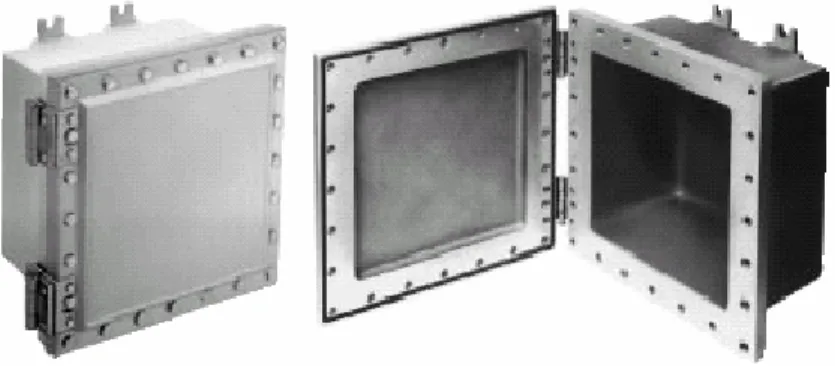
Figure 11 A Crouse Hinds Explosion proof Enclosure ... 55
1. Introduction
This manual has been developed for people involved in the installation of PV systems in Canada
A perusal of the Table of Contents of the Canadian Electrical Code (CEC) Part 1 will indicate that only one section (Section 50) deals with Photovoltaic Systems Installations. Rule 50-000(2), however, states that Section 50 is an amendment, which implies that all of CEC Part 1 applies to PV installations. This is indeed the case. Section 0 states “This code covers all electrical work and electrical equipment operating or intended to operate at all voltages in electrical installations for buildings, structures, and premises,…….”. There are 4 exceptions, namely; Utility Systems, Electric Railways, Aircrafts, and Marine Systems. These organizations have developed their own codes and standards and the CEC recognizes this.
Some explanation of how to interpret this manual is required. The material for this manual is based on the nineteenth edition of the Canadian Electrical Code Part 1, the 2002 CANADIAN ELECTRICAL CODE HANDBOOK and the authors’ experience.
This manual has 11 Chapters each of which deal with a specific section of the CEC. Not all sections of the CEC appear in this manual and those that do not appear have little or no relevance to PV installations. You will note that several methods have been used to quote the rules. In some cases the rule is quoted verbatim or is partially quoted, in others the rule is only referred to. The reader should have a copy of the nineteenth edition of the Canadian Electrical Code Part 1 available while reading this manual so they can read the full text of each Rule. The question, “Why develop a manual on the electrical code when the CEC book already exists?” may be asked. The answer is the CEC has been written primarily with conventional electrical systems in mind. This means that virtually all rules assume that the electrical circuits are AC but in many cases they still apply to DC systems and circuits (a Photovoltaic Modules generates DC). This manual identifies the existing rules that are pertinent to photovoltaic systems and assists the student in interpreting them from the point of view of DC systems and photovoltaic systems in particular. Further, the CEC states, “This code is not intended as a design specification nor an instruction manual for untrained persons.” This manual is specifically for persons learning about PV systems and also does provide some design guidance.
2. The Object of the CEC Section 2 and General Information
The purpose of this chapter is to discuss the layout of the Canadian Electrical Code Book, the Object of the CEC and sections, tables and appendices of the CEC that he/she may find useful when preparing to install a Photovoltaic System.
2.1 The Layout of the CEC Book
The CEC code book consists of 43 even numbered sections. Tables, Diagrams and Appendices are used to support and explain the rules. Section 50 deals specifically with PV systems but many of the other sections have rules that must be followed when installing PV systems (these are the sections that this manual deals with). Each section has a group of persons (see pages ix to xxii) considered to be knowledgeable with respect to that subject area that regularly discuss, revise and implement rules for that section. Anyone can submit a request for an amendment to the CEC and the form for submission is on page 424.
There are approximately 65 Tables that are of use to a designer and installer of electrical equipment. The tables that the PV Industry uses most frequently are:
Table 2 Allowable Ampacity of copper conductors in raceways and cables Table 5A Correction factors to Tables 1, 2, 3 and 4 for ambient temperature. Table 11 Conditions of Use for Various Types of Cords.
Table 12 Allowable Ampacity of Flexible Cord and Equipment Wire Table 16 Minimum Size of Bonding Conductors
Table 17 Minimum Size of Grounding Conductors for AC Systems Table 19 Conditions of Use of Wires and Cables
There are 10 pages of diagrams (pages 326 to 335) for use for very special applications. Diagrams 1 and 2 (pages 326 and 327) will be of interest for installations where a PV system is installed and DC is used rather than AC for operating equipment (see rule 26-700 (3)).
There are 9 Appendices. Appendix B provides backup information for each of the rules of Sections 0 to 86. Section 50 of Appendix B (pages 399) provides several diagrams very useful to those persons in the PV Industry.
Appendix D contains several tables that the PV installer may find useful. These are:
Table D2 Page 433 This table lists the rated currents of DC motors. Of course the voltages are higher than those normally encountered in PV systems; however a ratio can be used. For example a ¼ HP 120V motor has a listed current of 2.9 amps. The rated current for a 12V motor would be 120/12 x 2.9 or 29 amps etc.
Table D3 Page 434 This table can be used for determining conductor voltage drops. While the table is for a 1% drop on 120V systems, note 9 provides a formula to convert to any other voltage and % drop.
Table D4 Page 436 This table is similar to D3 but happens to be for 6V systems. The formulas at the bottom of the page indicate how to convert for other voltages. Both D3 and D4 are useful to a PV installer.
2.2 The Object of the CEC
Section 0 states the Object of the CEC - Which is to establish safety standards for the installation and maintenance of electrical equipment. This includes the prevention of fire and shock hazards and the operation of electrical equipment.
Section 2 of the Code sets general rules that are to be followed when undertaking an electrical installation. It is not the authors’ intent to discuss all of the material in Section 2 but to disuses only those rules of every day importance to PV system installers.
2.2.1 Rule 2-004: Permits
A permit is required prior to undertaking an electrical installation. The purpose of the permit is to insure that all electrical installations are installed by qualified persons. The purpose of this is to insure that someone qualified and experienced in electrical installations will be responsible for the installation. While the method varies from Province to Province the rules in place are intended to provide assurance to the system owner of a quality and safe installation. In Alberta only a qualified Journeyman Electrician is allowed to apply for an electrical permit. In BC only an Electrical Contractor is allowed to apply for a permit. To be an Electrical Contractor in BC the firm must have a journeyman electrician on staff. In most jurisdictions there is an exception that allows a homeowner to apply for a permit to undertake electrical work in their own home only. The homeowner must be qualified to do electrical work, but one would expect that a homeowner will not put themselves in danger.
2.2.2 Rule 2-006: Application for Inspection
A permit allows the installation of electrical equipment to proceed. At various milestones during the installation an inspection is required. Upon final inspection and approval by the inspector a permit to connect to the electrical supply is issued. If the installation is not satisfactory no connection permit will be issued.
The procedure outlined above provides checks and balances during the installation. The inspector has the authority to instruct changes to be undertaken if this is necessary. If the installation is not satisfactory then no connection to the supply will be made.
The above procedure also applies to a PV installation. A permit must be secured for the installation and regular inspections must occur. Unfortunately the final step of the process – the connection/no connection cannot be enforced. Because this final step cannot be enforced, many PV installations have been undertaken without a permit being issued. Hence no inspections have taken place and, in fact, many installations have been undertaken by unqualified installers. This is one of the major reasons for CanSIA undertaking the development and delivery of the PVT courses in conjunction with Canadian Colleges. One of CanSIA’s mandates is to promote safe and satisfactory PV installations.
2.2.3 Rule 2-24: Use of Approved Equipment
All equipment used in the electrical installations shall be approved for the application. This rule leads to the certification of electrical equipment. To be approved equipment must be tested for the application by a recognized testing agency and meet standards developed by the Canadian Standards Association. CSA certification is performed by a number of organizations such as, Electrical Testing Laboratories (ETL), Underwriters Limited (UL) and CSA International.
Until the early 1990’s certification was an issue for PV installations, particularly with respect to inverters and to the use of circuit breakers fuses and switches for the control of PV systems. Prior to the use of PV modules for generating electricity, residential and commercial electricity was all AC. Hence most residential and commercial electrical equipment was only certified for AC applications. Standards for PV modules, inverters and charge controllers did not exist and obtaining certified equipment usually meant a special inspection was required.
All equipment must be approved for the application. Lack of approval does not mean that a piece of equipment is unsuitable for an application, but it may mean that.
You will note that the title of the code book is the Canadian Electrical Code Part 1. There is also a Part 2 of the Canadian Electrical Code. The difference is that Part 1 is for Installation of Electrical Equipment whereas Part 2 is for the testing and approval of the Equipment only. This means that a PV module will be tested under Part 2 and, if approved, will be given a label indicating CSA compliance. An inspector when inspecting an installation may ask to see equipment approvals. If a piece of equipment does not have a CSA or equivalent sticker then he/she will not allow it to be connected.
2.2.4 Rule 2-308: Working Space About Electrical Equipment
Adequate space in front of and above equipment is necessary so that maintenance can be performed on electrical systems. Similarly, adequate lighting shall be provided for the operation and maintenance of equipment. This is a matter of safety for operating personnel. The minimum space in front of electrical equipment is to be 1 metre – IN ADDITION TO THE SPACE REQUIRED TO OPEN ENCLOSURE DOORS. The minimum head space is to be 2.2 m.
3. CEC Section 50 – Solar Photovoltaic Systems
3.1 Scope
As described in Rule 50-000(1), Section 50 applies to all photovoltaic systems except for those that meet the requirements for Class 2 circuits. Class 2 circuits are described in Rule 16-200(1)(a) and (b). These are circuits where current, voltage and power are limited so that they do not present as great a shock and fire hazard as those available from power circuits. [CEC Handbook]
Photovoltaic modules are current, voltage and power limited so there are many situations where a photovoltaic module may be part of a Class 2 circuit and the exception of Rule 50-000(1) would apply.
EXAMPLE:
A single photovoltaic module is directly connected to a small DC pump. The PV module has the following specifications:
Pmp 50 Watts Voc 21.5V Vmp 16.7V Isc 3.1A Imp 3.0A Is this a Class 2 circuit? Solution: Yes.
Rule 16-200(1)(b)(iii) applies since the open circuit voltage is over 20 V but does not exceed 30 V and the current is supplied from, “A device having characteristics which will limit the current under normal operating conditions or under fault conditions to a value not exceeding 100/V amperes, where V is the open circuit voltage; …”. In other words both the operating current (Imp = 3.0A) and the fault current (Isc = 3.1A) does not exceed, 100 divided by 21.5V = 4.65A.
It is also important to note that Rule 50-000(2) states that Section 50 is supplementary to, or amendatory of, the general requirements of the Canadian Electrical Code. In other words, all
photovoltaic systems must adhere to the general requirements of the Canadian Electrical Code including Sections 2 through 16 and Section 26.
A note in Appendix B places additional requirements on all solar photovoltaic systems, regardless of voltage and current ratings. If installed in hazardous locations, the requirements of Section 18 must be applied to these systems. See Chapter 10 for a discussion of Hazardous Locations.
3.2 Terminology
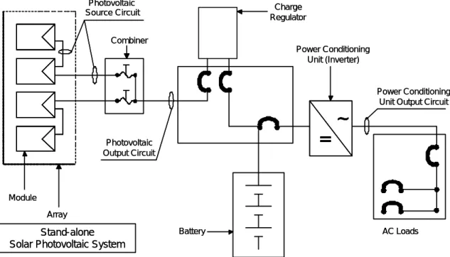
There are special terms used to describe the components and circuits within a solar photovoltaic system. These terms are defined in Rule 50-002 and are supplemented by a diagram in Appendix B. These definitions are specific to photovoltaic systems. Read Rule 50-002 and Appendix B and become familiar with the terms used to describe photovoltaic systems. Pay careful attention to the difference between the photovoltaic source circuit and the photovoltaic output circuit. The photovoltaic source circuit refers to only those conductors between modules and from the modules to the common connection point or combiner. The term Power conditioning unit is not a common term, but it refers to inverters and charge controllers.
Throughout this Chapter terms that are defined in Rule 50-002 and Section 0 will be used and highlighted in bold. Figure 1 identifies the main components and circuits of a stand-alone solar photovoltaic system.
Figure 1: Diagram for Identifying PV System Components 3.3 Marking
A permanent label shall be placed at the disconnect switch for the photovoltaic output circuit. Rule 50-004(1) states that the label must show the following information:
• Rated operating current and voltage; and
• Rated open-circuit voltage; and
• Rated short-circuit current.
This marking should be a permanent sign or label which is affixed to the enclosure which contains the disconnect for the PV array. In stand-alone systems a single enclosure, or Control Centre, often contains all the disconnects for the DC portion of the system.
Interconnected systems may have a disconnect for the photovoltaic output circuit located in the inverter. The information on the label allows the inspector to verify proper conductor ampacity and overcurrent device ratings. The label also enables the user, designer or installer to install the system, assess the performance of the system and make changes to the system. In addition to specifying the operating voltage and current, this rule also requires that the rated open-circuit voltage rated short circuit current be specified. Both the rated open-circuit voltage and short circuit current are higher than the operating voltage and current and therefore may present a hazard to operating personnel.
~
=
Photovoltaic Source Circuit Photovoltaic Output Circuit Power Conditioning Unit (Inverter) Power Conditioning Unit Output CircuitStand-alone Solar Photovoltaic System
Array Module Battery Charge Regulator Combiner AC Loads
~
=
~
=
Photovoltaic Source Circuit Photovoltaic Output Circuit Power Conditioning Unit (Inverter) Power Conditioning Unit Output CircuitStand-alone Solar Photovoltaic System
Array Module Battery Charge Regulator Combiner AC Loads
EXAMPLE:
A PV system contains a single module with the following specifications: Pmp 50 Watts
Voc 21.5V Vmp 16.7V Isc 3.1A Imp 3.0A
Write out a label for this system. Solution:
Solar Photovoltaic System
Operating Current 3.0 A
Operating Voltage 16.7 V
Rated Open Circuit Voltage
21.5 V Rated Short Circuit Current 3.1 A
Figure 2: Label for Solar Photovoltaic System
3.4 Voltage Rating
Photovoltaic modules are rated at Standard Test Conditions (STC) which stipulate a module
temperature of 25°C. The open-circuit voltage of a PV module is affected by temperature such that the open circuit voltage increases as temperature decreases. Thus if a PV array is operating at temperatures below 25°C, the electrical equipment in a PV system will be exposed to voltages greater than the open circuit voltage obtained at Standard Test Conditions. Rule 50-006 increases the voltage rating of the photovoltaic source circuit by 25% above the STC rated open circuit voltage. This ensures that the components of a photovoltaic system are chosen so they are not exposed to voltages exceeding their voltage rating when the photovoltaic modules are operating at temperatures below 25°C. Since there is nothing to prevent the voltages present in the photovoltaic source circuits from being present in the
photovoltaic output circuits, the rated voltages for the photovoltaic source circuits should also be applied to the photovoltaic output circuit.
Two PV modules, each rated 21 V open circuit at 25°C are connected in series before being connected to the combiner.
What is the rated open circuit voltage of the photovoltaic source circuit?
Solution:
2 modules in series x 21 V = 42 V 42 V x 125% = 52.5 V
Rated open circuit voltage is 52.5 V
3.5 Current Rating
Photovoltaic modules are current limited. The maximum current produced by a photovoltaic
module, or its short circuit current, depends on the intensity of sunlight striking the module
and the surface area exposed to the sunlight. The short circuit current of a photovoltaic
module is typically 10 to 15 percent higher than its operating current.
Photovoltaic modules are rated by manufactures at Standard Test Conditions which stipulate that the modules are exposed to sunlight at 1000 W/m2. 1000 W/m2 is a typical irradiance at sea level when the sun is directly overhead. However, reflected light from grass, snow, water or cloud formations can cause irradiance to exceed 1000 W/m2. Additionally, PV modules installed at higher elevations may experience higher irradiance due to less atmosphere between the module and the sun.
If overcurrent protection is not provided, Rule 50-008 states that the current rating of a photovoltaic source circuit shall be the rated short circuit current of all available photovoltaic power sources multiplied by 125%.
Often, several photovoltaic source circuits are connected in parallel at a common connection point or combiner. The output from the combiner is called the photovoltaic output circuit . If a fault occurs in one of the photovoltaic source circuits connected to a combiner, all the parallel
photovoltaic source circuits can feed the fault through the combiner. For this reason, if no overcurrent protection is provided, the current rating of any one photovoltaic source circuit
must be calculated based on all of the available photovoltaic power sources. The current rating for each photovoltaic source circuit is, therefore, the sum of the rated short-circuit currents of all the photovoltaic source circuits multiplied by 125%, and is the same as the current rating of the photovoltaic output circuit. The conductors in the photovoltaic source circuits are selected based on this current rating.
If overcurrent protection is installed in the photovoltaic source circuit, Rule 50-008 doesn’t specify what the current rating should be. However, Rule 8-104(1) states that the ampere rating of a circuit shall be the ampere rating of the overcurrent device protecting the circuit or the ampacity of the conductors, whichever is less. Therefore the current rating of the
photovoltaic source circuit is usually based on the overcurrent protection in that circuit. How does one choose the overcurrent protection in the photovoltaic source circuit? Good design practice dictates that the overcurrent protection for the photovoltaic source circuit
should be at least 125% of the rated short-circuit current of the photovoltaic module in that circuit. Doing so will avoid nuisance tripping of breakers or nuisance blowing of fuses during periods of increased irradiance, while still protecting the circuit in the event of a fault.
In some situations the 125% factor, which we have borrowed from Rule 50-008, is not adequate to prevent blowing of fuses when no fault is present. A combination of reflected light off snow and fog in parts of Canada has been reported to cause as much as an 80% increase in irradiance above Standard Test Conditions. In order to ensure reliable system operation, overcurrent protection, conductors and charge regulators may need to be chosen for operation under this extreme condition.
Refer to Chapter 6 and Rules 8-104(4), (5) and (6), which apply to the selection of equipment in the photovoltaic source and output circuits since the rated current, as calculated in Rule 50-008, should be considered a continuous load on the photovoltaic source circuit.
EXAMPLE:
A photovoltaic array comprised of three photovoltaic modules is connected via wire in raceway to a combiner, where the modules are connected in parallel. The module specifications are:
Pmp 50 Watts Voc 21.5V Vmp 16.7V Isc 3.1A Imp 3.0A
1. If no overcurrent protection is provided, what is the current rating of the photovoltaic source circuit?
Solution:
9.3A x 125% = 11.6 A
The current rating of the photovoltaic source circuit is 11.6 Amps
2. If overcurrent protection is provided in the form of fuses sized to operate at 125% of the rated short-circuit current, what is the current rating of the photovoltaic source circuit?
Solution:
First the size of the fuse must be determined. 1 module in parallel x 3.1A = 3.1 A
3.1A x 125% = 3.875A
The load on the photovoltaic source circuit must be considered continuous and Rule 8-104(5)(a) applies (See Chapter 6). The fuse size should be:
3.875A / 80% = 4.84A (rounded up to 5 Amps)
The current rating of the photovoltaic source circuit is 5 Amps
There is a Maximum Fuse Size stated in the specifications for any UL listed photovoltaic
module. This Maximum Fuse Size takes into account both the 125% factor of Rule 50-008 and the requirements of Rule 8-104. Although this Maximum fuse size is based on the National Electrical Code, using the maximum fuse size recommended by the manufacturer as protection for the photovoltaic source circuit should enable one to meet the requirements of the Canadian Electrical Code.
Rule 50-008 should not be interpreted to mean that overcurrent protection is not required in the photovoltaic source circuit. Stand-alone systems often have a battery. A fault in the
photovoltaic source circuit could occur such that the battery supplies fault current to the
photovoltaic source circuit which exceeds the rated ampacity of the components and conductors in the circuit. Read Rule 50-010, which addresses whether overcurrent protection is required.
3.6 Overcurrent Protection
The requirements of Section 14 apply to the overcurrent protection for photovoltaic conductors and apparatus. Rule 50-010(1) states that when the available short-circuit current does not exceed the rated ampacity of the electrical apparatus or conductors in the circuit, overcurrent protection is not required. If the available short circuit current is less than the ampacity of the conductors or apparatus, then a hazardous condition should not exist in the event of a fault.
However, the total of the current ratings of all photovoltaic source circuits and the fault current available from the battery must be taken into account when applying this rule. Overcurrent protection will be required between the battery and the photovoltaic source circuits since batteries are a source of very high fault currents.
According to Rule 50-010(2), if overcurrent devices are installed for the photovoltaic source circuits, they shall be accessible and grouped where practicable. If a combiner is used, this is the appropriate place for the overcurrent devices, but this may pose a problem if the combiner is located near a photovoltaic array located on the roof of a building. According to the definitions in Section 0, Accessible means the equipment is not guarded by locked doors, elevation or other effective means. Therefore Rule 50-010(2) may preclude installing a combiner with overcurrent protection near a roof mounted photovoltaic array since access to most roofs is either locked or requires a ladder. Photovoltaic system installations are still a relatively new practice in Canada and this rule illustrates why it is a good idea to contact the electrical inspector before commencing work so that difficulties in interpreting the rules of the CEC may be worked out ahead of time.
3.7 Disconnecting Means
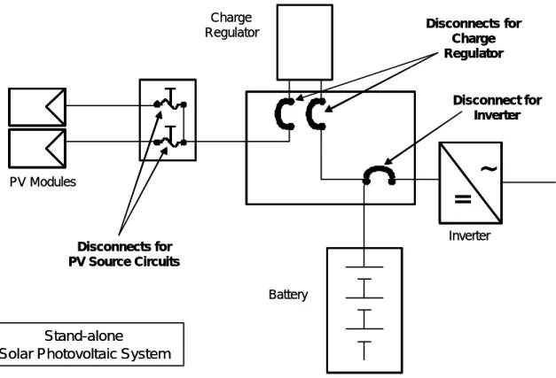
Photovoltaic modules are energized whenever exposed to light and a battery is always energized. Thus it is important in a photovoltaic system that a means is provided to disconnect all equipment from all ungrounded conductors of all sources as describe din Rule 50-012(1). This will allow safe servicing of equipment in the photovoltaic system. Figure 3 illustrates the placement of disconnecting means in a photovoltaic system. Pull out fuses are often used in the combiner and these can serve as the disconnect means if they are listed for operation under load. Some types of attachment plugs, as described in Rule 50-016, may also be suitable as a disconnect means if properly rated for disconnection under load.
Note that simply disabling a photovoltaic array by placing an opaque covering over the modules does not satisfy the requirements of 50-012. An opaque covering does not isolate the
equipment. Furthermore, read Rule 14-700 which specifically states that diodes, transistors and other solid state devices are not suitable for disconnecting or isolating equipment.
~
=
Inverter
Stand-alone
Solar Photovoltaic System
PV Modules
Battery Charge
Regulator
Disconnects for PV Source Circuits
Disconnects for Charge Regulator Disconnect for Inverter
~
=
~
=
Inverter Stand-aloneSolar Photovoltaic System
PV Modules
Battery Charge
Regulator
Disconnects for PV Source Circuits
Disconnects for Charge Regulator
Disconnect for Inverter
Figure 3 Placement of Disconnect means in a Stand-alone PV System
Typically the charge regulator in a photovoltaic system is supplied by two energy sources and requires a disconnect means for each source of energy. This is also shown in Figure 3.
Modules, panels and arrays may be connected in parallel with other modules, batteries and even power sources such as wind generators. Thus the equipment in a photovoltaic system is often energized from more than one source. If this is the case, Rule 50-012(2) states that the installation must comply with Rule 14-414.
3.8 Wiring
Rule 50-014 makes an exception from the general rules for the interconnection of PV modules. In most PV installations, Section 12 allows photovoltaic modules to be interconnected with wires and cables in accordance with Table 19 of the CEC. Read Chapter 4 for more information on wire types and conductors. The most common wire types used for PV module interconnection are single conductor RW90 in raceway, Tray Cable (where properly supported), NMWU and TECK90.
However, Rule 50-014 also allows flexible cords of a type specified in Table 11 of the CEC for extra-hard usage to be used. For example, SOW meets this requirement and is often used to interconnect the modules in PV arrays that actively track the motion of the sun. Stranded or flexible wire is preferred for making module interconnections.
3.9 Module Interconnection
Attachment Plugs and Similar Wiring Devices shall be permitted for the connection of flexible cord between photovoltaic modules or panels. Rules 50-016 states that these devices must have the following characteristics:
• No exposed parts
• Polarized
• Non-interchangeable
• Locking
• Properly rated
• Provide strain relief
The bonding conductor plays an important safety function and safe working procedures require the presence of this conductor so that all equipment is bonded to ground. According to Rule 50-018, removal of a photovoltaic module or panel shall not interrupt the bonding conductor to other photovoltaic modules. This Rule requires that modules not be bonded in a daisy chain such that removing a module during service or maintenance would leave remaining modules without a bond to ground. Read Chapter 7 for more information on Grounding and Bonding.
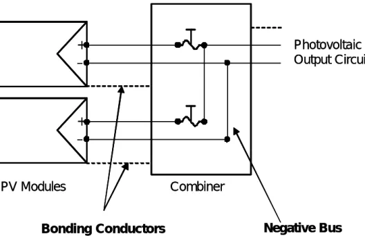
Although Rule 50-018 requires module connections to be arranged so that the bonding conductor is not interrupted when a module is removed, there is no specific rule that requires the installation of photovoltaic modules so that removal of a module or panel from a photovoltaic source circuit does not interrupt the identified conductor. However, Rule 4-034 requires that devices installed in multi-wire branch circuits shall be installed such that they may be disconnected without interrupting the continuity of the identified conductor. Further more, Rule 4-026(d) stipulates that a neutral conductor be installed so that any neutral conductor may be disconnected without disconnecting any other neutral conductor. If the same logic is applied to photovoltaic systems in which the negative is grouned, a negative bus arrangement such as provided in a combiner should be used so that PV modules may be removed from a PV array without interrupting the identified conductor in the other
photovoltaic source circuits. Figure 4 illustrates the proper connection of the bonding and negative (identified) conductors in a combiner. Note that the bonding conductors are between
the frame of the photovoltaic modules and the enclosure of the combiner. A bonding conductor also runs from the combiner to the main DC disconnect along with the photovoltaic output circuit.
PV Modules
Bonding Conductors
+
+ – –
Negative Bus
Combiner
Photovoltaic Output Circuit
PV Modules
Bonding Conductors
+
+ – –
Negative Bus
Combiner
Photovoltaic Output Circuit
Figure 4 Arrangement of Bonding and Negative Conductors in a Grounded System 3.10 Interconnected systems
Rule 50-020 applies to photovoltaic systems that are interconnected with the utility or supply authority. Rule 50-020(1) states that the equipment in an interconnected system must be connected in compliance with Section 84. Section 84 applies to the installation of consumer-owned electric power generation equipment connected and operating in parallel with another
supply authority system.
Take note of Rule 84-002 which states, “interconnection arrangements shall be in accordance with the requirements of the supply authority.” The utility that owns the distribution system (the supply authority) which a photovoltaic system is to be interconnected with has the last word on how that interconnection is to be made. Utilities that allow the interconnection of photovoltaic systems will publish their own document outlining such requirements. Typically this document will reference documents from organizations such as CSA, IEEE and/or the IEC and explicitly state the parameters that such systems must operate within and the applicable equipment standards. For example, CSA C22.2 No 107.1-01 is the applicable standard for inverters used in interconnected systems.
Rule 84-026 is also of particular importance. This rule lists the requirements of the disconnecting means for a parallel generation system. Since Rule 84-026(1)(c) states the disconnecting means shall, “have contact operation verifiable by direct visible means…”, molded case switches or circuit breakers are not acceptable. Safety Switches with visible blades are most often used for this application.
50-020(2) allows either a dedicated branch circuit breaker or a fused disconnect on the load side of the service box to be used as the point where the photovoltaic system ties into the building electrical distribution system. No electrical loads may be connected to the branch circuit breaker or fused disconnect and it should be labeled as being the power conditioning output circuit.
4. CEC Section 4 – Conductors
4.1 Scope
Rules 4-000 and Rule 4-002 define the scope Section 4 and the minimum wire size for electrical circuits covered by the CEC Part 1. PV source circuits, output circuits, etc. are power supply circuits and thus Section 4 applies to photovoltaic installations.
4.2 Ampacity of Wires and Cable
Rule 4-004 describes the tables that must be referred to when determining if a conductor has the required ampacity for a circuit. Conductors carrying current produce heat due to the resistance of the wire. This Rule and the Tables it refers to, are designed to prevent the temperature of a conductor from exceeding the temperature rating of its insulation while carrying its rated current or ampacity.
Two rules from Section 8 also apply to the selection of conductor sizes. Rule 8-102 states the requirements for voltage drop in a circuit and Rule 8-104 imposes limitation on the current a conductor may carry based on the calculated load in the circuit. Wire size selection most be checked against both of these rules in addition to the Tables described in Rule 4-004. Read Chapter 6 for more information on Rules 8-102 and 8-104.
Conductor size in a PV system will be chosen on the basis of either the current carrying capacity of the conductor or on the voltage drop – whichever results in the greater size. Often, in PV systems operating at nominal 12 V or 24 V the conductor sizes chosen to limit voltage drop will have ampacities that exceed the current they are required to carry.
The current carrying capacities calculated from the information in Tables 1 through 5C are the maximum values for various conductor types and insulation types under various conditions of operation. These tables are valid for both direct current (DC) and alternating current (AC). By definition, the heating value of a DC Amp is equivalent to the heating value of an AC Amp. Table 1 through Table 4 are used depending on the material the conductor is made from. Tables 1 and 2 are for copper and Tables 3 and 4 are for aluminum. A further distinction is made between conductors installed in free air or in raceway or cable. A conductor that is enclosed within a raceway or cable is not going to dissipate heat as rapidly as one in free air and thus the ampacities in Tables 1 and 3 for free air, are generally slightly greater for a given wire size than those in Tables 2 and 4, which are for conductors installed in raceway or cable.
Tables 5A, 5B and 5C are used to modify the data in Tables 1 through 4. Table 5A provides correction factors for conductors operating at ambient temperatures above 30°C, Table 5B provides correction factors for Tables 1 and 3 when more than one conductor is present and the conductors are in contact, and Table 5C provides correction factors for cables or raceway that contains more than three conductors.
Table 5A will be used quite extensively in selecting conductors for the photovoltaic source circuits. Photovoltaic modules are often installed on roofs where the ambient temperature may exceed 30°C, and the PV modules often have surface temperatures 20°C to 30°C above the ambient temperature. The conductors for the PV modules are usually installed in junction boxes attached directly to the back of the module and thus the ambient temperature within the junction boxes is essentially the same as the module temperature. Conductors operating at high ambient temperatures can carry less current because the ambient temperature plus the temperature rise created by the current must not exceed the temperature rating of the insulation.
EXAMPLE:
Two conductors of copper RW90 in raceway comprise the photovoltaic source circuit in a photovoltaic array. Each source circuit is protected with a 10 amp fuse. The maximum operating temperature of the photovoltaic module is 70°C. What size conductor is required?
Solution:
Since the source circuit is connected directly to the PV module its temperature will be approximately the same as the PV module. From Table 5A, Row 70°C and Column 4: 85-90°C, the Correction Factor is 0.52 and the ampacity of the conductor must be at least:
A A
23 . 19 52 . 0
10 =
From Table 2, Column 4: 85-90°C, at least a #12 AWG conductor, with ampacity of 20A, is required for this circuit.
4.3 Insulated Conductors
Rule 4-006 refers to Table 19 which lists the uses for the various types of approved insulated conductors. The table also lists the maximum allowable conductor temperature. Many of the Wire and Cable types may be used in more than a single condition of use. For example you will note that TECK90 may be used in almost all conditions of use. The conductors used for the photovoltaic source circuits will be either exposed, or installed in raceway and must also be suitable for use in wet locations. PV module interconnection are often single conductor RW90 in raceway, Tray Cable (where properly supported), NMWU and TECK90.
EXAMPLE:
RW90 may be used under what conditions? Solution:
RW90 is listed for the following conditions of use:
• For exposed wiring in wet locations
• For exposed wiring where exposed to the weather
• For use in raceways, except in cable trays, in wet locations
• For use in ventilated and non-ventilated cable trays in vaults and switch rooms
• For concealed wiring used as non-heating leads on heating panels and panel sets
4.4 Flexible Cord
Rule 4-010 limits the uses of Flexible Cord so that it would not ordinarily be used in a permanent solar photovoltaic system unless that system used a solar tracker. Rule 4-010(2)(g) permits the use of Flexible Cord for, “The connection of electrical components between which relative motion is necessary;”. Since a solar tracker would create motion between the PV modules and the combiner, Flexible cord may be permitted. However, Refer to Chapter 3: Section 50 – Solar Photovoltaic Systems and see Rule 50-014 which amends this interpretation and explicit permits flexible cord to be used for the interconnection of modules. The size of flexible cord is limited by Rule 4-012. Flexible cord shall be not smaller than a No. 18 AWG copper conductor, except for certain conditions which do not apply to photovoltaic source circuits.
For current carrying capacity, Rule 4-014 refers to Table 12. For 2 or 3 conductors in a flexible cord, the maximum current any copper conductors of a given size may carry is specified in Table 12. Note that Table 12 is based on an Ambient Temperature of 30°C. Although there is no specific rule, it is advisable to determine the Temperature Rating of the flexible cord one is using from Table 11 and apply appropriate temperature derating factors from Table 5A.
4.5 Colour of Conductors
Rule 4-036 states the requirements for the colour of grounding and bonding conductors, which shall be green or green with a yellow stripe. The Rule goes further to state the required colours of the current carrying conductors in a circuit. Rule 4-036(3) is quoted below as it is very specific about the colour of the conductors in dc circuits.
4-036 Colour of Conductors
Where colour coded circuits are required, the following colour coding shall be used, except in the case of service-entrance cable and insofar as Rules 4-030, 4-032, and 6-308 may modify these requirements:
1 phase ac or dc (2-wire) —1 black and 1 red or
1 black and 1 white*† (where identified conductor is required); 1 phase ac or dc (3-wire) — 1 black, 1 red, and 1 white*†; 3 phase ac — 1 red (phase A),
1 black (phase B), 1 blue (phase C), and
1 white* (where neutral is required) *Or natural grey;
†Or white with coloured stripe (see Subrule 4-034).
Rule 4-036(3) specifies that two wire dc circuits should be black and red, or black and white if an identified conductor is required – i.e. if the system is grounded the grounded conductor, which is usually negative, should be white. This white conductor is the system conductor that is bonded to the grounding system and is at the same potential as the earth. Read Section 0 where the term identified is defined. Under definition (a) it states, “… the conductor is either a grounded conductor or a neutral …”. Also refer to Chapter 7 and the definition of grounded in Section 0.
This colour coding may result in confusion as the convention in electronics and automotive wiring is that the positive conductor is red and the negative is black. Using red as the positive and white as the negative may be acceptable in certain applications and will help avoid mistakes – check with the electrical inspection authorities to make sure.
5. CEC Section 6 – Services and Service Equipment
5.1 Scope
Section 6 of the Canadian Electrical Code Part 1 applies to services, service equipment and metering for electrical installations. The requirements of Section 36 may apply to installations exceeding 750 V, but for most photovoltaic interconnected or stand-alone systems Section 36 does not need to be referenced.
Although there is no actual supply authority for a photovoltaic stand-alone system, there are still rules in Section 6 that may apply to such an installation. On the other hand, an interconnected system has a supply service, but the scope of a photovoltaic installation would generally not include this service equipment. Nonetheless, because power circuits are entering a building, the installation of the photovoltaic output circuit from the PV array to the main PV array disconnect may be similar to the installation of consumer’s service conductors to the service box especially if exposed conductors are used. See Chapter 6: Section 8 for more on this similarity.
Some PV systems use a separate structure to house the battery and inverter in much the same way that people will construct a separate generator shed (in fact the generator may also be housed in the same structure as the battery and inverter – in separate rooms). When this is done, the conductors from the separate structure become the Consumer’s Service Conductors and Section 6 is very relevant to the installation of AC components of the system.
5.2 Overhead Conductors
Rule 6-112 is relevant to photovoltaic installations that include overhead conductors. This rule is intended to protect people and vehicles from contact with overhead conductors. Thus requirements for the clearance of the conductors above finished grade are stipulated and the location and structural characteristics of the point of attachment are also stipulated. The point of attachment should be sufficiently high and strong such that snow and ice accumulation, in addition to the weight of the conductors, will not cause the conductors to sag, the service mast to bend or pull fasteners from the building.
If the PV system is using exposed wiring for the photovoltaic source circuits or photovoltaic output circuit, refer to Chapter 8 which covers Section 12 including Rules 12-300 to 12-318, which are specific to exposed wiring.
5.3 Terminating Conductors
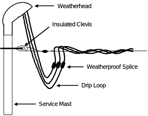
Rule 6-114 is intended to protect cables and conduit from water infiltration. This can be accomplished by using a rain-tight service head, cable terminations suitable for exposure to the weather, or tape or heat shrink tubing. Drip loops and suitable clamps, fittings or terminations to hold cables securely in place are also required as shown in Figure 5
Drip Loop Weatherhead
Service Mast
Insulated Clevis
Weatherproof Splice Drip Loop
Weatherhead
Service Mast
Insulated Clevis
Weatherproof Splice
Figure 5: Rain-tight service head, indicating drip loops and attachment
5.4 Consumer’s Service Equipment Location
Rule 6-206 sets out the requirements for the location of service boxes or other service equipment. The equipment must be readily accessible or have the means of operation readily accessible. In addition the equipment should be located within the structure being served and located as close as practicable to the point where the consumer’s service conductors enter the building. (see Consumer’s Service Conductors Location below) In a stand-alone photovoltaic system, the service equipment may include the DC disconnect for the PV array and the inverter. However if a separate structure houses the battery and inverter the Service Equipment only includes the AC wiring and the Service Equipment is more conventional.
There is an exception to this rule if the environmental conditions within the structure are unsuitable. Some of the unsuitable conditions are described in 6-206(1)(c) and include dangerous or hazardous locations.
If the service equipment is located outside, it must be protected from both the weather and mechanical injury. This will entail using proper weatherproof enclosures and raceway or conduit for protecting conductors.
5.5 Consumer’s Service Conductors Location
Rule 6-208 requires service conductors to be located outside of buildings except in special circumstances described in Rules 6-208(1)(a), (b), and (c). The raceway or cables containing the consumer’s service conductors may only enter the building to connect to the service box.
There are established methods in the electrical industry for installing overhead conductors, terminating conductors in wet environments and installing consumer’s service conductors. These methods are readily adapted to the installation of photovoltaic source circuits and photovoltaic output circuits. Figure 5 shows some of the details for bringing overhead wiring into a building, but such techniques are beyond the scope of this manual.
6.
CEC Section 8 – CIRCUIT LOAD AND DEMAND FACTORS
6.1 Scope
Rule 8-000 defines the scope of Section 8.
It covers the conductor ampacity and equipment ratings for consumers services, feeders, and branch circuits and the number of branch circuit positions for residential buildings.
8-108 discusses the number of branch circuits required in a residential dwelling however these rules assume that the branch circuits are supplied with 120V AC. Since the scope of this manual is the DC only portion of a PV system rule 8-108 will not be discussed.
There are 2 factors that are used to determine the size of a conductor: either the current capacity of the conductor or the ohmic voltage drop of that conductor. Whichever method results in the larger conductor size is the one that must be used. Section 4 discusses the selection of conductors on the basis of current carrying capacity and the use of Tables 1 through 5C, but Section 8 also contains rules that apply to conductor selection.
6.2 Conductor Selection on the basis of Current Carrying Capacity
Since CEC Part 1 is primarily written for AC systems and based on electrical energy distributed by a Supply Authority, Section 8 has been written with that in mind. In these systems a consumers service consists of the conductors between the connection to the Supply Authority and the main disconnect in a residence. Thus the Rules governing Services and Feeders, Branch Circuits and Automobile Heater Receptacles would be difficult to apply to a PV system since many of the assumed loads are not practical in a PV system. Nonetheless, the AC wiring of a residence or structure should be wired in compliance with Section 8 to allow for future changes such as extension of the utility grid.
6.3 Voltages to be used when determining conductor current ratings
Voltages to be used for calculating currents are specified by 8-100 and are the normal AC voltages of 120, 208, 240, 277, etc. The voltages used for PV systems typically span the extra low voltage and low voltage of CEC Part 1 definitions (see definition of Voltage in Section 0). Because the service voltages of most PV systems are 12V, 24V or 48V, and the conductor voltage drop may have a major impact on the operation of a PV system, the actual voltage rather than nominal values should be used. When the system includes batteries the battery voltage must be used – and the battery voltage will vary with the SOC. For convenience Figure 6 has been reproduced from PVT210.
Battery Open Circuit Voltage State of Charge Specific Gravity Cell Voltage 12 V 24 V 48 V
Fully Charged 1.2650 2.12 12.72 25.44 50.88 75% 1.2250 2.10 12.60 25.20 50.40 50% 1.1900 2.08 12.48 24.96 49.92 25% 1.1550 2.03 12.18 24.36 48.72 Discharged 1.1200 1.95 11.70 23.40 46.80
Figure 6 Battery State of Charge
EXAMPLE 6-1
A 24V PV system supplies a summer cottage. On the basis of Figure 6, determine the voltage to be used to determine the current in the conductors:
a. Between the PV array and the fused disconnect ahead of the battery. b. Between the batteries and the loads.
Solution
a. When determining the current rating of a conductor the maximum possible current must be determined. Typically a calculation is required to determine that current. The maximum current between the PV array and the battery will be determined by the short circuit PV module rating and Rule 50-008. Hence, the basis of the current rating will be the nameplate of the module and not the voltage of the battery.
b. If the battery supplies an inverter the maximum current will occur when the battery voltage is lowest, therefore use 23.4V.1 If there is no inverter and the battery is supplying resistive loads, the maximum current will occur at maximum voltage, hence use the highest voltage of 25.4V.
When close to the maximum rating for that conductor always choose the next larger conductor. (See Section 0, CEC page 1 paragraph 3).
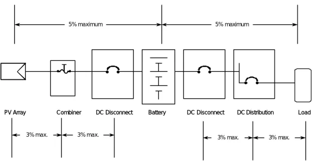
6.4 Conductor Selection on the basis of Voltage Drop
The maximum voltage drop for AC systems is governed by 8-102 and is specified as 3% for any portion of a circuit and 5% overall. For the purposes of PV systems the photovoltaic
1
Note that discharged does not mean that there is no current available. Terminal voltage is an indication only of SOC. A battery with a terminal voltage of say 23.5 V will still yield considerable current to a load.
source circuits and photovoltaic output circuits may be interpreted as feeders and/or branch circuits In PV Systems the maximum voltage drop allowed between the PV array and the battery is 5%, with no more than 3% allowed on any portion of the circuit. Feeder and Branch circuits on the DC side should be treated as though they were AC circuits. Figure 7 illustrates this concept.
PV Array Combiner DC Disconnect Battery
3% max. 5% maximum
3% max.
DC Disconnect
3% max. 3% max.
5% maximum
Load DC Distribution
PV Array Combiner DC Disconnect Battery
3% max. 5% maximum
3% max.
DC Disconnect
3% max. 3% max.
5% maximum
Load DC Distribution
Figure 7 Maximum Allowable Voltage Drop in Circuits
There is always the question of what to take as the current when determining the voltage drop. Subrule 2 states that if the actual current is not known then one is to use 80% of the rating of the overload device protecting that conductor. This is reasonable since a fuse or circuit breaker exposed to its listed rating will take a considerable time to trip. Instantaneous trip currents will be considerably higher than the name plate value.
Conductors to be used for PV systems shall follow this rule. The size of a conductor is to be based on the maximum current that can exist in that conductor and then choose from the conductors listed in Tables 1 to Table 4 of the CEC as long as the voltage drop meets the 3% or 5% rule. For 120V AC circuits and systems Tables 1 to 4 will be correct in most applications. For the DC portion of PV systems, because of the voltages used, a conductor selected based Tables 1 to Table 4 may have a voltage drop greater than that allowed by Rule 8-102.
EXAMPLE 6-2
Specify the size of copper conductors to be used in the photovoltaic output circuit, connecting the combiner box of a 24V PV 152A array to the battery disconnect, if the one way distance is 5 metres.
Solution:
Table 2 specifies that 14 AWG is rated at 15A. But what is the voltage drop for this conductor? By 8-102 it shall not be greater than 3% or in this case 0.72 volts. Ohms law, can be used to determine the voltage drop. Table 10 of PVT100 states that the resistance of #14 AWG is 8.46 Ω/km. The voltage drop will be:
Vd = current times resistance
= 15A x 8.46Ω/1000 x (2 x 5m) = 1.27V
Since the voltage drop is higher than that allowed, the next larger wire (a #12 AWG) must be chosen – as long as it will meet the requirement of less than a 3% drop. It is left to the reader to determine this.
Alternate Solution:
Using Table D4, #12 wire can conduct 15 A with 5% voltage drop a one-way distance of 1.9 meters at 6 Volts. Using the formula provided the maximum run length for 3% voltage drop is:
m A
A V
V
m 4.56
15 15 6
24 % 5
% 3 9 .
1 × × × =
4.56 meters is less than 5 meters. Therefore #12 is not suitable, according to Table D4, and #10 would have to be used.
2
In this case to keep things simple we are assuming that the 15A array current is already enhanced by 125% (see 50-008)
6.5 Maximum Circuit Loading
Rule 8-104 appears at first reading to be confusing and contradictory. Unfortunately code rules have developed over time and generally they do not get rewritten – they only have additions. In plain words Rule 8-104 states that conductors and equipment must not carry more than the current that they are rated for. 8-104(1) states that the lesser rating of either the conductor or the overcurrent device3 determines the maximum allowable current in a circuit. Some electrical equipment is rated as continuous at 100%, as described in Rule 8-104(4) and some is rated continuous at 80% of rated current, as described in Rule 8-104(5).
Some loads are continuous and some are intermittent and Rule 8-104(3) explains how to determine this. An examination of Tables 1 to 4 and Tables 5A to 5C will indicate that the rated current of a wire depends upon size, the type of conductor, the ambient temperature, the number of conductors in contact and whether it is a cable or in free air. With all of these variables it becomes very difficult to produce rules that ensure the compliance to the first sentence – conductors and equipment must not carry more current than they are rated for. It is best to proceed using a step by step process, which might be:
1. Determine the calculated load using 8-104(3) and 50-008 if working on the photovoltaic source circuits.
2. Select the conductor to be used from Tables 1 to 4 (Insulation types, hence
temperature –Columns 2, to 7) and whether a cable (Tables 2 or 4) or free air (Tables 1 or 3) or whether copper (Tables 2 or 4) or aluminum (Tables 1 or 3).
3. Select the overcurrent device or other equipment that it will be connected to (is it rated at 100% or only 80%)4
4. Ensure that the conductor is still cable of carrying the rated current of the selected overcurrent device.
5. Ensure that the voltage drop of the conductor is not more than 3%5.
EXAMPLE 6-3
3
An overcurrent device is interpreted as a fuse or circuit breaker. Most frequently it is a circuit breaker.
4
Examine the name plate ratings. If it does not indicate continuous at 100% then it mu st be taken as 80% of the nameplate rating. See 8-104, Appendix B.
5
Remember – individual voltage drop cannot exceed 3%. 5% is the overall total voltage drop. Add all of the individuals up – the sum shall not be greater than 5%.
A stand-alone solar system consists of 6 – 64 Watt 12 V modules each having a short circuit current of 4A connected to charge a 24V battery that supplies an inverter. Specify the conductors and disconnect switch for the photovoltaic output circuit that connects the combiner box to the charge controller for this system. Assume that the conductors are copper and in a RW90 cable installed totally within the building. The one-way length of the cable is 5 metres and the disconnect switch does not have a 100% continuous rating. Assume the circuit configuration is that shown by 50-002 in Appendix B.
Solution
As indicated above it is best to use a step by step approach to select the components Step 1: Determine the load (current)
This is a 24 V system used to charge a battery. The voltage to use will be as given by Figure 6 and the module current in this case must be taken as 125% of the short circuit current (50-008) and modified depending upon whether it is deemed to be continuous (8-104(3)(a)). The sun certainly can persist at 100% for more than 1 hour in any 2 hour period.
The rated current is:
12 x 1.25 =15A (3 strings of 2 modules in series). Step 2: Select the service conductors
The conductors are copper, in a cable and inside the building; hence the temperature will be not greater than 30°C6 hence select #12 AWG.
Step 3: Select the Switch Rating
The current is rated as continuous (8-104(3)(a)) and the switch to be used is not rated 100% continuous therefore it must be de-rated by 80% (8-104, Appendix B), hence the rating of switch must be 15A/0.8 = 18.75 A.
Switches do not have fractional ratings hence the next larger must be selected. The switch to be used must have name plate rating of 20A or greater. Step 4: Check the voltage drop
In this case the section that we are concerned with is classified as a feeder circuit hence it must comply with the 3% rule.
L= 24/6 X 3/5 X 15/18.75 X 1.9 = 3.65 m
Even # 12 AWG too small! Using the same equation for #10 yields 5.95 metres.
The wire to be used to connect the combiner box to the overcurrent device must be #10 AWG.
6
7. CEC Section 10 – GROUNDING AND BONDING
Grounding and Bonding are difficult concepts for many people to grasp. Generally, the question is “Why are systems grounded and bonded”? Rule 10-002 provides the answer to this question and it is:
• To protect life from the danger of electric shock, and property from damage by bonding to ground non-current-carrying metal systems; and
• To limit the voltage upon a circuit when exposed to higher voltages than that for which the circuit is designed; and
• In general, to limit ac circuit voltages-to-ground to 150V or less on circuits supplying interior wiring systems; and
• To facilitate the operation of electrical apparatus and systems; and
• To limit the voltage on a circuit which might otherwise occur through exposure to lighting
There is considerable confusion regarding grounding and bonding and the differences between the two. Section 0 defines the two terms.
Bonding means a low impedance path obtained by permanently joining all non-current-carrying metal parts to assure electrical continuity and having the capacity to conduct safely any current likely to be imposed on it.
Grounding means a permanent and continuous conductive path to the earth with sufficient ampacity to carry any fault current liable to be imposed on it, and of a sufficiently low impedance to limit the voltage rise above ground and to facilitate the operations of the protective devices in the circuit.
Enclosures of electrical equipment are connected together with a conductor (they are bonded) and the bonding conductor is connected to earth. And because an electrical system is grounded (connected to earth) this also means that the enclosures of electrical equipment will be at earth potential regardless of the type of fault or the magnitude of current that happens to be in the bonding or earthing conductor.
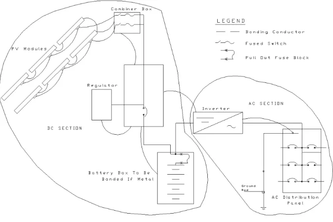
Figure 8: Drawing of typical PV System with Bonding Conductors 7.1 Grounding
A perusal of Figure 8 will indicate that for a typical PV system there are 2 distinct circuit sections – the DC section and the AC section. We must observe the rules for each section.
7.1.1 The DC Section
For voltages between 50 V and 300 V inclusive, DC systems must be grounded as indicated by 10-102(1).
10-102 Two-Wire Direct-Current Systems
(1) Two-wire direct-current systems supplying interior wiring and operating at not more than 300 V or not less than 50 V between conductors shall be grounded, unless such system is used for supplying industrial equipment in limited areas and the circuit is equipped with a ground detector.
For voltages less than 50 V Rule 10-114, provides guidance.
10-114 Circuits of Less than 50 V.
Circuits of less than 50 V shall be grounded: (a) Where run overhead outside of buildings
(b) Where supplied by transformers energized from: …
For the PV case (a) is applicable and the rationale as stated by the Handbook is that out of door wires may be exposed to higher AC voltages (i.e. a supply grid). While a standalone system such as Fig 7 is unlikely to be exposed to supply grid wires it definitely is exposed to lightning. Grounding (and bonding) will insure that the all components of a PV system will be at ground potential by providing a low electrical resistance path to earth for lightning strikes. There is one other interesting aspect to solar systems (both PV and thermal). It is that a solar module mounted and exposed to the sun is essentially a large flat plate capacitor (a conductive plate with insulation on each side) and as such under certain atmospheric conditions will become charged with respect to earth (as does a cloud). Grounding and bonding will insure that any static charge will be neutralized.
10-114(b) does not have any relevance as there will be no transformers on a DC system.
10-104: Three-Wire Direct Current System
The neutral conductor of all 3-wire direct-current systems supplying interior wiring shall be grounded.
This rule is in keeping with the object of grounding (see 10-002) which is to limit voltages for interior wiring to 150 V or less. PV systems designed for grid tied applications typically operate at much higher voltages than those designed for stand alone applications. Typical grid tied inverter output voltages are 120 V or 208 V. By connecting modules in series the input voltage to the inverter will be approximately the same as the output voltage thus eliminating the need for a transformer. The intent of 10-002 can be met by using a 3 wire system i.e. a conductor is connected to the electrical center of the array and then grounded. Thus the maximum voltage to earth is 50% of the maximum system voltage. By definition this conductor becomes a neutral (see section 0).
As indicated by 10-002 the purpose of grounding and bonding is to protect life from the danger of electric shock. Grounding and bonding achieves this by ensuring that when an electric fault occurs the potential of the metal parts of enclosures will be maintained at a safe value with respect to earth and/or the fault will cause the system to be disconnected by a protective