© 2018, IRJET | Impact Factor value: 6.171 | ISO 9001:2008 Certified Journal | Page 1297
Obstacle Detection and Collision Avoidance System
Mr. Dnyaneshwar V. Nimse
1, Prof. S. B. Abhang
21,2Department of Electronics and Telecommunication
JSPM Narhe Technical Campus,Pune-411041 Savitribai Phule Pune University, Pune -411007
---***---Abstract - The most common of accident being
unavoidable is a bane of any society. Obstacle detection has been topic of much concern since past few decades. Accidents can be unintentional and sometimes can be random but are generally found to occur due to the unexpected obstacles on the moving path. Warnings can be like alarm and beep, if the vehicle is approaching a pothole, or any moving obstacle, driver can be warned in advance regarding what the road entails. Describe the design of the obstacle detector irrespective of their movements. It detect the discontinuities in terrain and alerts users of potential hazards like open manholes, protrusions, etc. which are common on Indian roads. Hence, automobile safety can be improved by anticipating a crash before it occurs and providing additional time to deploy safety technologies.
Key Words: MATLAB, Robot, camera, PIC Controller, Image Processing.
1. INTRODUCTION
Road safety is not an issue that will resolve itself, every citizen has responsibility for actions. We commit our combined knowledge, technology and network to promote safety. Between 25 percent and 33 percent of global crash are work related and 36 percent of occupational deaths worldwide are due to road crashes. Hence, crash avoidance system and devices help the driver and, increasingly, help the vehicle itself to avoid collision. This literature survey implement one such safety subsystem, Adaptive Cruise Control (ACC) using the ultrasonic sensors. This system uses an ultrasonic set up to allow the vehicle, to slow when approaching another vehicle or obstacle and accelerate again to the pre-set speed when traffic allows. ACC technology is widely regarded as a key component of any future generations of smart cars, as a form of artificial intelligence that may usefully be employed as a driving aid.
Adaptive nonlinear coordinated control strategy is
propose strong nonlinearities and parametric
uncertainties. The task of longitudinal control autonomous vehicles is tracks desired velocity or desired safe distances in real-time while maintaining stability and riding comfortably. In nonlinear cascade longitudinal control system with inner and outer loops proposed to ensure safety and comfort of autonomous vehicles. In the practical implementation longitudinal velocity controls, sliding mode control technique.
This application measure range in terms of physical distances and controls the speed of the motors. As the transit time of the echo drops below each threshold the duty cycle of signal varies and thus speed is controlled. On the other hand, motion sensors senses motion by analyzing sound waves in its environment. Some just listen for sounds while others send out ultrasonic signals and analyze how they are reflected back. This type of motion sensor is often used in home security systems as well as it can also be used in automobiles to detect the sudden appearance of any object on the path and hence based on the threshold of duty cycles again the speed is controlled. In Autonomous base vehicle system detection of vehicle for avoidance of collision avoidance system by PC camera and by MATLAB coding help to protect. By pixel formation of data through linear way avoid collision of system.
The motion planning layers is responsible computing safe, comfortable, and dynamically feasible trajectory from the vehicle current configurations to the goal configuration provide by the behavioral layer of the decision making hierarchy. Depending on context, the goal configuration may different. For example, the goal location may be the center point of the current lane a number of meters ahead in the direction of travels, the center of the stopped lines in next intersections, or the next desired parking spots. The motion planning components accepts information about statics and dynamics obstacle rounded vehicle and generate a collision-free trajectory that satisfies dynamics and kinematic constraint on the motion of vehicles. The motion planner also minimize a given objective functions. In addition to travel times, the objective function may penalize hazardous motions or motions that cause passenger discomfort. In a typical setup, the output of the motion planner is then passed to the local feedback control layers. Feedback controller generates input signals to regulated the vehicle to follow this given motion plan. A motion plan for the vehicle can take the form of a path or a trajectory. Note that such a solution does not prescribe how this path should be follow, ones can either choose a velocity profile for path or delegate this task to lower layers of the decision hierarchy. Within the trajectory planning framework. Control execution time is explicitly considered. This consideration allows for direct modeling of vehicle dynamics and dynamic obstacles.
© 2018, IRJET | Impact Factor value: 6.171 | ISO 9001:2008 Certified Journal | Page 1298
2. LITERATURE REVIEW
Avery, Wang and Rutherford [1] propose digital image processing algorithms for length base vehicle classifications. Use stream of image capture from un-calibrate video camera. Actually compares length of different vehicle, to estimate the trucks volume, eliminate needs of different complex calibration system. Implemented length classifications algorithm on trucks, get 92% accuracy under condition.
Zhang, Avery, Wang [2] describe length base classification techniques are important for transportation planning. This data cannot be measurable by single hardware detectors. They developed Video-Based Vehicle Detection and Classification System (VVDC) for the collection of trucks relate data. They divide VVDC system into six module for capturing of live video, get user input, extraction of backgrounds, vehicle detection, shadow removal, length base classifications. Their defined algorithm got 97% accuracy for classifying trucks. But this VVDC systems can’t handle longitudinal vehicles occlusion. Camera movement and head-light reflection problems.
Wu, Zang, Xu, Song [3] reviewed different video vehicles classification technique and suggest that video base vehicles classification are more advantageous than any other classification techniques. Explain different video base vehicles classification technique such as optical flow field, background removals, edge detections, frame differential, gray comparison techniques. They highlighted that no doubt video detectors are advantageous but still have many resolved issue. Issues resolved by using better and appropriate vehicles classification algorithms.
Wang [4] presented an approaches for detecting the moving vehicle, removal of cast shadow for video base traffic monitoring, control systems. He developed an algorithm to handle non-stationary backgrounds for vehicle detection in live video streams. Method significantly improve overall performances of vehicle detection and shadow removal process.
Qin [5] used basic techniques for vehicle classification by analyzing images taken from video. Firstly he set up road background relative to the different serial image. By using background division he segment vehicle region and calculate the moment invariant features. These features were passed as an input to the BP neural networks. The network is divided into three layers such as Light Vehicles, Heavy Vehicles, Intermediate Vehicles. Neural network help in classifying the autonomous vehicle type more efficiently, effectively. One of the reasons for the popularity of a method it is simplicity, elegance.
Lai, Huang, and Tseng [6] used a technique of three basic steps. These steps are use by any of the vehicle classification techniques. The steps were vehicle region extraction, vehicle tracking and classification. They
adopted the techniques of background subtraction in order to extract the foreground. By applying some geometric parameter it removes the false edge and shadow from the images. After vehicle detection, tracking method is used for creating the correspondence between the detect vehicle at different time intervals. Vehicle classifications are done by using two metrics, aspect ratio and level of compactness.
3. RELATED WORK
3.1 The Proposed System
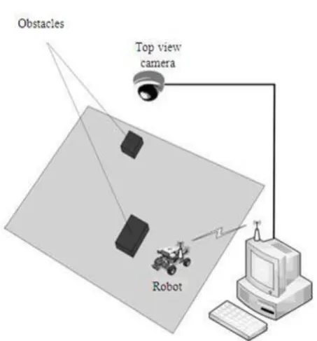
Fig -1: Principal architecture of vision based autonomous mobile robotic systems.
The main advantages of digital image over analogue is longevity of the digital medium (although this assumes a well-manage archiving strategies). Even carefully store film or glossy pictures will become brittle in 20 years, and is also subject to physical damages that cannot be repairs. Analogue images cannot be accurately copy or reproduce into multiple generations without loss of data, degradation or alteration of original material.
[image:2.595.320.547.232.476.2]© 2018, IRJET | Impact Factor value: 6.171 | ISO 9001:2008 Certified Journal | Page 1299 A second advantage of the digital image is its
ability to reproduce the original with far more exactitude than analogue images can be done. Digital capture at resolutions employed by DIAMM , involves the acquisition of a far greater quantity of information than analogue. Most of this information is not visible to the naked eye except under extreme magnification, but this sort of magnification are possible in digital medium. The basic digital images tolerates for more enlargement without graining than its analogue counterpart would.
Because analogue developed processes required the use of human judgmental equally as much as any technical processes to produce the final image, any close study of color and ink bleed (for example) would be pointless less conduct on the original source. Given the fragility of most of the source from the Medieval period, this would be highly desirable.
When photo labs make a reprint either from a print or from its negative they are rarely, if ever, able to reproduce the colors of the original print precisely, because they reply both on human judgments and the use of chemical process that are too inaccurately calibrated to be exactly reproduce.
The mechanism by which we perceive colors is still only partially understood, but one ordinary ability of the brain, chromatic adaptation, which enables us to function normally in changing light conditions becomes a handicap, it is dealing with precise colors balancing. As an example, if you put on a pair of dark glass, the lens will completely change the real colors reaching your eyes. However, a split-second adjustment in the brain allows us to continue to recognized correctly and understand color even through a very heavily tint filter.
All capture device from scanner to hand held camera required calibration to determine how the CCD respond to color. Archival digital scanning work is done with consistent daylight balanced lighting: this increases the scan time but ensures a more accurate results. Since the light is continuous (unlike flash), exact calibrations of the captured equipments will ensure a correct records of the lighting conditions.
Direct digital acquisition from the original sources ensures both stability of the colors balance, the quality of the information, which remain true to the original because it is not subject to transformation from the analogue to the digital languages. As long as the equipment used to view or print the image is correctly calibrated, and makes correct use of the embedded profile of the capture equipment, the user will see correct colors either on screen or when the digital images is print. No post-processing (sharp masking to correct poor focus, level adjust to correct exposure, color adjustment, etc.) should be necessary on a correctly scan or photographed image. If
any post processing are required, then the image has not been properly taken, and the work must be done.
4. RESULTS
1. If no interrupt from any side then robot is move in straight direction. Its, result is given below
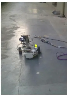
Fig -2:. Actual system with no interrupt.
The obstacle detection is carried out by software, which analyzes and processes scene images captured by a (vision) camera installed on the ceiling inside the site, where the robot and the obstacles are located.
After building a computer model of the site with its different objects (the robot and the obstacles), the system starts planning the routing path that reaches from the current point to other possible end points. The methods and techniques used for building the model are image processing and computer vision. The former involves manipulating a digital image to generate a second image that differs in some respects from the original one.
LASM byte code is sent to the RCX from a PC via infrared data transfer, usually from a tower connected to the PC via USB or RS-232 (serial) cable. Two motors built in the robot are used to provide all possible motions including forward, reverse, right and left turns.
Actually in that system no interrupt from any side so, robot move in foreword direction.
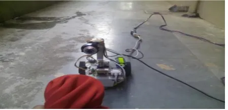
[image:3.595.364.503.172.368.2]© 2018, IRJET | Impact Factor value: 6.171 | ISO 9001:2008 Certified Journal | Page 1300 Fig -3: Free system without obstacle.
There is no obstacle for interrupt to robot. So. There is linear position between them. MATLAB not showing any correspondence of interrupt and its scanning check by every millisecond.
In order to execute the reference path or trajectory from the motion planning system a feedback controller is used to select appropriate actuator inputs to carry out the planned motion and correct tracking errors. The tracking errors generated during the execution of a planned motion are due in part to the inaccuracies of the vehicle model. Thus, a great deal of emphasis is placed on the robustness and stability of the closed loop system. Many effective feedback controllers have been proposed for executing the reference motions provided by the motion planning system.
3. If interrupt from left side then robot is move to right direction. Its, result is given below
Fig -4: Actual system with left side interrupt.
It checks resolution between 640 * 480 pixel format. From above resolution it is clear that x-axis is 355 and y-axis is 150 therefore for area is 136327. This gives response of red color because MATLAB coding design for red color configuration. It is clear that object gives interrupt from left side. By RS 232 serial communication,
It take command from PC to LM323 IC to avoid collision. Therefore with the help of coding it gives command to system to move in right direction. Its actual system configuration with real-time system in MATLAB showing coding.
[image:4.595.312.558.186.328.2]4. Its coding in MATLAB shows left side interrupt. Is given below.
Fig -5: MATLAB coding for left side interrupt.
There is a obstacle from left side to robot. By using MATLAB coding it shows x-axis is 355 and y-axis is 150 therefore for area is 136327. By RS 232 serial communication, It take command from PC to LM323 IC to avoid collision.
5. If interrupt from right side then robot move to left direction. Its, result is given below.
Fig -6: Actual system with right side interrupt.
[image:4.595.337.530.469.599.2] [image:4.595.58.267.507.663.2]© 2018, IRJET | Impact Factor value: 6.171 | ISO 9001:2008 Certified Journal | Page 1301 6. Its coding in MATLAB shows its right side interrupt. Is
[image:5.595.39.286.116.270.2]given below.
Fig -7: MATLAB coding for right side interrupt.
There is a obstacle from left side to robot. By using MATLAB coding it shows x-axis is 128 and y-axis is 205 therefore for area is 103648. By RS 232 serial communication, It take command from PC to LM323 IC to avoid collision. It checks resolution between 640 * 480 pixel format. From above resolution it is clear that x-axis is 128 and y-axis is 205 therefore for area is 103648. This gives response of red color because MATLAB coding design for red color configuration. It is clear that object gives interrupt from left side. By RS 232 serial communication, It take command from PC to LM323 IC to avoid collision. Therefore with the help of coding it gives command to system to move in right direction. Its actual system configuration with real-time system in MATLAB showing coding.
[image:5.595.324.546.151.300.2]7. If interrupt from opposite side then robot is stop. Its, result is given below.
Fig -8: Actual system with opposite side interrupt.
It checks resolution between 640 * 480 pixel format. From above resolution it is clear that x-axis is 260 and y-axis is 198 therefore for area is 144591. This gives response of red color because MATLAB coding design for red color configuration. It is clear that object gives interrupt from opposite side. By RS 232 serial communication, It take command from PC to LM323 IC to avoid collision. Therefore with the help of coding it gives
command to system stop. Its actual system configuration with real-time system in MATLAB showing coding.
8. Its coding in MATLAB shows opposite side interrupt. Is given below.
Fig -9: MATLAB coding for opposite side interrupt.
Autonomous robotic system based on the previous and current obstacle information its next motion course concludes, thereby avoiding to collide with the obstacles. In this example, the robot moves in the vertical direction. Within this state, the parameters for the most adjacent obstacle (Fig. 5) that are necessary for controlling the robot movement inside the environment have these values: “side = obstacle to the right of the robot”, “closeness = contact” and “obstacle motion = to the right”. Accordingly, the motion decision for the robot is “Turn to the left to bypass the obstacle”.
5. CONCLUSION
This paper discuss the different techniques of obstacle detection vehicle. But these technology are complicated, costly and have some limitations while operating in real time. By overcoming all these limitations, proposed system in this paper is simple, cost-efficient and robust and also have row detection capability. The proposed control strategy possesses better tracking performances and enhances the riding comfort and stability of autonomous vehicles, even under adverse driving conditions.
REFERENCES
[1] Ryan P. Avery, Yinhai Wang, and G. Scott Rutherford,” Length-Based Vehicle Classification Using Image from Un-calibrat Video Camer”, Intelligent Transportation System, 2004 Proceedings. The 7th International IEEE Conference.
[image:5.595.51.276.527.636.2]© 2018, IRJET | Impact Factor value: 6.171 | ISO 9001:2008 Certified Journal | Page 1302 [3] Kun Wu, Haiying Zhang, Tianmao Xu, Ju Song,
“Overview of Video Base Vehicle Detection Technologies”, The 6th International Conference on Computer Science & Education (ICCSE 2011) August 3-5, 2011. SuperStar Virgo, Singapore
[4] Yang Wang,, “Real-Time Moving Vehicle Detections With Cast Shadow Removal in Video Base on Conditional Random Field”, IEEE transactions on circuit, system for video technology, vol. 19, no. 3, March 2009
[5] Zhong Qin,” Method of Vehicle Classification Base on Video”, Proceedings of the 2008 IEEE/ASME International Conference on Advanced Intelligent Mechatronic July 2 - 5, 2008, Xi'an, China