© 2017, IRJET | Impact Factor value: 5.181 | ISO 9001:2008 Certified Journal | Page 3441
A New Complexity Reduced Hardware Implementation of 16 QAM
Using Software Defined Radio
K.Bolraja
1, V.Vinod kumar
2, V.JAYARAJ
31
Nehru Institute of Engineering and Technology, PG scholar, Dept. of ECE
2
Nehru Institute of Engineering and Technology, Assistant prof, Dept. of ECE
3
Nehru Institute of Engineering and Technology, HOD, Dept. of ECE
---***---Abstract
–
The proposed software defined radio (SDR) isfully focused on a communication system that used for modulating, demodulating, coding and decoding of data. This paper mainly concentrated for hardware implementation of 16 QAM specifications to create a SDR. The practicability of using Mathworks to test, design and prototype the Quadrature amplitude modulation (QAM) gives better result than conventional model.
Key Words: 16-QAM, BENCHMARK WICOMM-T, SDR,
Transceiver, MATLAB.
1.INTRODUCTION
This paper focused on the design and implementation of a SDR. This allowed for greater accuracy and flexibility when designing the communication system. This paper focused on using the 16 QAM specification to create a SDR the coding and modulation scheme. The paper also focused on rapid development and prototyping by using Simulink MATLAB program and benchmark WI-COMM Trainer board.
The transceivers are designed with hardware. So, incase if we need to do any research activities by modifying the modulation technique, frequency and amplitude levels, filters etc. we need to change the entire hardware which is a time consuming and cost implementing process. SDR (software defined radio) is the concept in which these research activities can be implemented at ease of time. It uses a generic hardware that is a radio that can be driven with any type of modulation signals.
2. PROPOSED 16 QAM USING SDR
SDR is the concept in which these research activities can be implemented at ease of time. It uses a basic hardware that is a radio that can be driven with any type of modulation signals. This is achieved by using software like MATLAB or Lab VIEW to drive the hardware. So, for any further modifications we can modify the source code and this system acts as a test bed. In the conventional communication system, the modulation concept is implemented with hardware. The transmitter and receiver are designed with hardware. So, in case if we need to do any research activities by modifying the modulation technique, frequency and amplitude levels, filters etc. we need to change the entire
hardware which is a time consuming and cost implementing process.
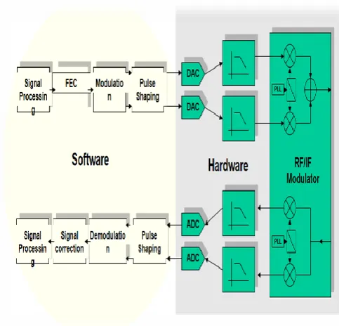
2.1 Proposed System Block Diagram
Fig -1: Proposed system block diagram
2.2 QAM Modulator & Demodulator
The QAM modulator and demodulator are fundamental elements within any communication system. The modulator and demodulator are used to encode the signal, often data, onto the radio frequency carrier that is to be transmitted. Then the demodulator is used at the remote end to extract the signal from the RF carrier so that it can use at the remote end.
2.2.1 16 QAM Modulator
[image:1.595.310.552.271.503.2]© 2017, IRJET | Impact Factor value: 5.181 | ISO 9001:2008 Certified Journal | Page 3442
Fig -2: 16 QAM ModulatorThe two main resultant signals are get summed together and finally get processed in the chain of RF signal, generally converting signal in frequency domain requires final frequency and amplification also required. The RF amplifier must be linear to save the integrity of the data signal. If any non-linearities content present in the data causes altering of levels of the signal and phase difference. This will cause distortion in the signal and possibility of error data.
2.2.2 16 QAM De Modulator
The reverse process of QAM modulator is known as QAM demodulator. Initially the signal get spited in each side is then
applied to the mixer circuit.
Fig -3: 16 QAM De Modulator
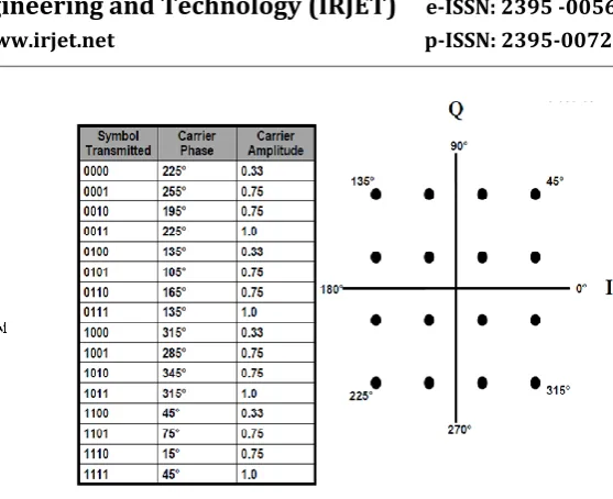
2.2 Constellation Diagrams For QAM
The constellation diagram is to represent the signal modulated by the digital modulation scheme like the quadrature amplitude modulation or the phase-shift keying. The constellation diagram displays signal as the two dimensional X and Y plane scatter diagram in a complex plane at symbol sampling instants.
Fig -4: 16 QAM constellation vs symbol tx and 16 QAM constellation IQ(º)
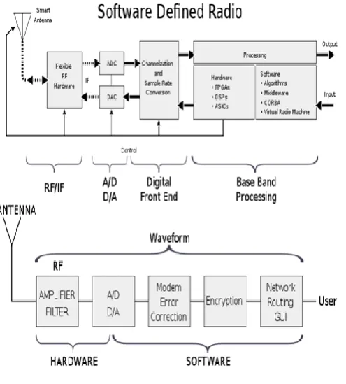
2.3 Software Defined Radio
A software defined radio is defined as a form of transceiver in which ideally all aspects of its operation is determined using versatile, general-purpose hardware whose configuration is under software control. This is often thought of in terms of base-band digital signal processers (DSPs).
2.3.1 Proposed Software Defined Ratio (
SDR)The SDR is a kind of communication system where the components are typically implemented in hardware. Then they are get implemented by the means of software domain on any kind of embedded system or personal computer. Although it may kind of sound a trivial exercise, creating the definition for the SDR is not as case of simple as it seems. Finally it is also essential to produce the strong definition for many reasons together with standards issues, regulatory applications and for activating the SDR technology to move forwards more quickly.
Many descriptions have appeared that might cover a description for the SDR. The SDR Forum they have defined in the two main types of radio containing software in the following fashion:
Software Controlled Radio: The radio in which all the physical layer’s and some function are controlled by software. This kind of radio only uses software for to provide a control of a various functions that are fixed within the radio.
[image:2.595.278.557.53.280.2] [image:2.595.41.278.102.279.2] [image:2.595.36.290.443.633.2]© 2017, IRJET | Impact Factor value: 5.181 | ISO 9001:2008 Certified Journal | Page 3443
Fig -5: Block diagram of software ratio2.5 Benchmark Wireless Communication Trainer
Kit
The Benchmark Wireless Digital communication training system WiCOMM-T is the real implementation of a modern digital communication system with connected to MATLAB through the high speed USB port of a PC. The system is implemented using the three main functional blocks of any modern digital communication systems and gadgets viz. Data Processing Block, ADC - DAC conversion block and RF block.
It is a versatile training system to cover the important concepts of wireless digital communication which includes digital modulation techniques, Baseband Equalization, pulse shaping concepts and the basics of CDMA, GSM, and OFDM etc. The MATLAB interface easily provides to generate essential signal and send it to a real life wireless digital communication system. The MATLAB interface also provides the user with the flexibility to try out other topics of Digital communication on their own.
3. SIMULATION RESULTS
The proposed 16 QAM Using SDR is implemented and simulated using MATLAB7.1 on a Personal computer equipped with 2GHZ operating speed 2GB RAM and benchmark wicomm-t hardware kit.
3.1 16 QAM Output Analyses
Fig -6: Receiver Block diagram in MATLAB
A RRC pulse with a roll off factor defined by the user is generated by Figure 7 shows the generated RRC pulse and fig 8 shows the impulse response of the RRC pulse. The random data generated is up sampled by number of samples in one bit duration. These are quadrature data. Then I and Q data are convolved with the RRC pulse to obtain the pulse shaped bits. Finally, 16-QAM modulated data is given to the WiCOMM-T Tx interface block to send it through WiCOMM-T. The samples are received from the WiCOMM-T Rx interface as blocks, the received samples are then get downsampled using RRC filter. The filtered signals are then 16-QAM demodulated and Bit error rate (BER) is calculated and results are stored.
3.2 Transmitter output analyses
3.2.1 RRC Pulse
The phase response is linear within the bandwidth of interest and the group delay is constant within the bandwidth as shown in Figure 7.
Linear phase mainly point to the condition where in the phase response (Pr) of the filter is straight line (linear) function of the frequencies. This causes in the delay though a filter being the equal at all the frequencies. So the filter doesn’t cause phase distortion or delay distortion.
[image:3.595.40.288.114.389.2] [image:3.595.319.550.127.263.2] [image:3.595.367.523.618.747.2]
© 2017, IRJET | Impact Factor value: 5.181 | ISO 9001:2008 Certified Journal | Page 3444
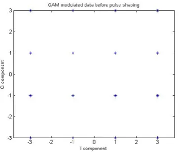
Fig -8: Impulse response of RRC Filter3.2.1 QAM Modulated Data Before Pulse Shaping &
After Pulse Shaping
[image:4.595.56.284.96.234.2]Fig -9: QAM modulated data before pulse shaping
Fig -10:QAM modulated data after pulse shaping
[image:4.595.317.514.126.308.2]3.2.2 Output analyses of Receiver
Fig -11:Eye diagram for IQ pulse
In the transmitter, the generated signal from the random integer generator is modulated by the 16-QAM modulator, which has a symbol rate of 2.5 M symbol/s. The ideal eye figure of the generated 16-QAM baseband signal is shown in Fig 9, whereas the constellation diagram output is shown in Fig 10. The modulated signal is subsequently upconverted by a factor of 16 QAM and pulse-shaped by the RRC filter.
Fig -12:Demodulated data eye diagram IQ pulse
4. CONCLUSIONS
[image:4.595.50.233.321.475.2] [image:4.595.324.541.450.630.2] [image:4.595.45.248.506.673.2]Re-© 2017, IRJET | Impact Factor value: 5.181 | ISO 9001:2008 Certified Journal | Page 3445
usable and re-configurable modules that realize multimodemodems, e.g., in an SDR framework [10], overcomes memory/ DSP processing power (or FPGA gate-count/ speed) limitations, without compromising performance.
REFERENCES
[1] E. Agrell, K. Eriksson, A. Vardy, and K. Zeger, “Closest
point search in lattices,” IEEE Trans. Inf. Theory, vol. 48, no. 8, pp. 2201–2214, Aug. 2002.M.
[2] A. Chan and I. Lee, “A new reduced-complexity sphere
decoder for multiple antenna systems,” in Proc. ICC, New York, Apr. 28–May 2 2002, vol. 1, pp. 460–464.IEEE signal processing letters, vol. 13, no. 9, september 2006
[3] A. Due-Hallen, “A family of multiuser decision-feedback
detectors for asynchronous code-division multiple-access channels,” IEEE Trans. Commun., vol. 43, no. 234, pp. 421–434, Feb.–Mar.–Apr. 1995.
[4] J. Jaldén and A. Ottersten, “An exponential lower bound
on the ex- pected complexity of sphere decoding,” in Proc. ICASSP, Montreal, QC, Canada, May 17–21, 2004.
[5] X. Luo, and M. Kisialiou, “An efficient quasimaximum
like- lihood decoder for PSK signals,” in Proc. ICASSP, 2003.
[6] C. Ching, and Z. Ding, “Semidefinite relaxation based
multiuser detection for M-ary PSK multiuser systems,” IEEE Trans. Signal Process., vol. 52, no. 10, pp. 2862– 2872, Oct. 2004.
[7] T. N. Davidson, K. M. Wong, Z.-Q. Luo, and P.-C.Ching,
“Quasi-ML multiuser detection using semi-definiterelaxation with ap- plication to synchronous CDMA,” IEEE Trans. Signal Process., vol. 50, no. 4, pp. 912–922, Apr. 2002.
[8] R. Sotirov, and A. K. Khandani, “A near maximum
likelihood decoding algorithm for MIMO systems based on semi-definite programming,” in Proc. Int. Symp. Information Theory, Sep. 4–9, 2005, pp. 1686–1690.
[9] A. Stamoulis, G. B. Giannakis, and A. Scaglione, “Block
FIR decision- feedback equalizers for filterbank precoded transmissions with blind channel estimation capabilities,” IEEE Trans. Commun., vol. 49, no. 1, pp. 69–83, Jan. 2001.
[10] Jeffry. H. Reed, “Software Radio a modern approach to
radio engineering”, Prentice Hall PTR, A division of person education Inc, ISBN 0-13-081158-0, pp.33-12, 2002
[11] D.Zafor and R.Farooq,"Implementation and Analysis of
Qpsk & 16 QAM Modulator & Demodulator," vol.2,P.64 -68, Norember ,2008.
[12] M.S. Naghmash ,M.F. Ain, C.Y.Hui,"FPGA Implementation