POWER SPEED REDUCTION UNITS FOR GENERAL AVIATION
PART 4: SIMPLIFIED GEAR DESIGN FOR PISTON-POWERED,
PROPELLER-DRIVEN “HEAVY DUTY” AIRCRAFTS
AND HELICOPTERS
Luca Piancastelli1 and Stefano Cassani2
1Department of Industrial Engineering, Alma Mater Studiorum University of Bologna, Viale Risorgimento, Bologna (BO), Italy 2MultiProjecta, Via Casola Canina, Imola (BO), Italy
E-Mail: [email protected]
ABSTRACT
Bending fatigue (Strength) or surface compression/lubrication (Hertz stress) and scuffing resistance define aerospace gearing design and optimization. In addition, a correct design method must include adequate ability to resist all these types of failures. Of all the failures modes, tooth bending has the most severe consequences, whereas pitting and scuffing are durability-type failures that can be (theoretically) anticipated and corrected before final failure. However, in helicopter transmission pitting and scuffing are the main failure cause. Therefore, it is important for the designer to understand the criticalities of the different application. The third paper dealt with the general problem of designing the PSRU (Power Speed Reduction Unit) gear drives on a general aviation propeller-driven aircraft. This fourth part deals with aerobatic/racing/STOL-utility “heavy duty” aircrafts and with helicopters. In the first part of this paper, a verification method of a “general aviation PSRU” for a heavy duty aircraft is introduced. Then helicopter transmissions are discussed, starting from the most suitable gear types, the transmission architecture and the main problems. Bevel gearing are briefly introduced by defining design criteria, suitable materials properties and selection method. Then the flash temperature concept is briefly summarized along with experimental data on the most advanced steel alloys available on the market.
Keywords: PSRU, aircraft, piston engine, gear drive, involute.
INTRODUCTION
In PSRU (Power Speed Reduction Unit) drive system, gears reduce/increase speed, change the direction of drive, and split/combine torque paths. A designer has several different types of drive configurations to select from, in order to best achieve the intended function. Spur, helical, and planetary gears transmit power along parallel
axis. Bevel, worm, and face gears transmit torque along intersecting axis. For helicopter transmissions, efficiency is the main problem. In fact, efficiency is directly linked to lubrication and cooling. For heavy duty aircraft, strength is more critical, since these PRSU are usually derived from “general aviation” ones. Table-1 outlines the gear types, functions, and typical uses in aerospace transmissions.
Table-1. Gear types and applications.
Gear type Axis type Function Typical use
Spur Parallel Speed reducer Combined/Split paths
Aircraft PSRU Planetary gearing Accessory gearbox
Tail Rotor gearbox Helical Parallel Combine/Split paths Speed reducer High speed, high load Aircraft PSRU
Bevel Intersecting Speed reducer Direction change Combine/Split paths Intermediate gearboxes Change drive direction
Face (still
experimental) Intersecting
Speed reducer Direction change Combine/Split paths - 90°
direction change
High gear ratio Crown/collector gear
Aircraft gearing design is based on bending fatigue. In fact, of all the failures modes, tooth bending has the most severe consequences.
On the contrary, pitting is the second important constraint for helicopter gears that run always close to top speed. Scuffing (scoring) failure occurs when the mating gear welds the metal surface of the mated gear. Although scoring is not a fatigue failure, excessive compressive stress over a period of time induces radial scratch lines in the surface that promotes the onset of scoring. Scuffing is
a durability failure that may occur instantaneously. Heavily loaded, high-speed gearssuch as helicopter gears tend to fail by scoring. The probability of a gear pair to resist scoring is called scuffing resistance. A correct design method must include adequate resistance to all these types of failures.
bearings. For this reason, double helical gears are common in aerospace.
As we will see in this paper, helix angles over 30° are critical. In theory, relative to a spur gear, the effective face width and line of contact in a helical mesh is longer due to the angled nature of the tooth face. This generates higher contact ratios than spur gears and improves load sharing. This improved load sharing should permit smoother meshing, reduces noise and better handles higher speeds and torque. Practically, misalignments and deformations partially reduce the helical gear advantage. Bevel gears are the primary option to change direction between intersecting axis. The shaft angle between the intersecting axis is typically between 0º and 115º, with 90º being the most common angle. Straight bevel gears with radial teeth are to be avoided being extremely critical. Spiral (Gleason) bevel gears with curved teeth are far more common.
Load model
A load model is the worst-case operating scenario, which realistically define environment in which the gearing is intended to operate. Therefore, it is extremely critical that, early in the design process, the requirements establish a load model for any system being designed or evaluated. From that model, the designer calculates the loads and number of cycles, which the scenario imposes on the various parts. It is then possible to design the components to achieve the desired life under those loads and durations.
Table-2 shows a typical heavy-duty aircraft load model using the torque curve from a turbocharged 1, 000 HP CRDID (Common Rail Direct Injection Diesel) [1] [2] [3] engine and a set of flight conditions, which reasonably approximate worst-case usage of a “heavy duty” aircraft.
Table-2. Aerobatic/racing/STOL-utility “heavy duty” aircrafts load model.
# Load step Crankshaft speed rpm Torque Nm Time % Cycles x106
1 Climb+ Aerobatics Take off + Steep 6000 1170 15 122.4
2 Max. eff. Climb. 5500 1200 10 66
3 Max Cruise 5200 1000 20 124.8
4 Cruise 4800 800 53 305.3
- Total - - 100 618.5
The load model of Table-2 has no idling/low-power considered. In this type of aircrafts, idling time is very short [4] [5]. For comparison, Table 3 shows a load cycle for a general aviation aircraft. For aircrafts, an acceptable TBO is 2,000h. As it can be seen the “heavy
duty” cycle is much more critical with nearly 125millions of cycles at maximum output power vs. the 0.72 of a general aviation aircraft. The total number of cycles is also nearly doubled.
Table-3. General aviation aircraft load model.
# Load step Crankshaft speed rpm Torque Nm Time % Cycles x106
1 Take Off 6000 1170 0.1% 0.72
2 Climb 5500 1000 1% 6.6
3 Cruise 4800 800 78% 450
4 Idling 2000 - 20.9% 50
- Total - - 507
Table-4 shows the load cycle of a helicopter. In this case, the TBO is 3, 000h. Table-4 shows that the most critical factor of helicopter is the very high number of cycles, nearly three times the general aviation aircraft. The
Table-4. Helicopter load model.
# Load step Crankshaft speed rpm Torque Nm Time % Cycles x106
1 TO 6000 1079 0.9 9.72
2 Hover-1 6000 1170 1.9 20.5
3 Cruise-1 6000 803 40 432
4 Hover-2 6000 1032 1.9 20.5
5 TO-2 6000 630 1.1 11.9
6 Cruise-2 6000 464 42 464
7 Cruise-3 6000 574 11.8 127.4
8 Hover-2 6000 555 0.4 4.3
- Total - - 100 1080
Table-4 also shows that the helicopter engine and transmission run at constant speed with extremely variable loads (torque).
Table-5. Engine data.
Engine type V12@60° Injection/Firing (even) 1-12-5-8-3-10-6-7-2-11-4-9
Power max 1,000HP@6000rpm
Rpm_max 6,200rpm
Torque_max 1,250Nm@3800rpm Torque@max _power 1,170Nm@6000rpm
Idling rpm 1,000rpm
Table-5 shows the main data for a CRDID (Common Rail Diesel Direct Injection Diesel) piston engine. This engine is used as the reference piston engine for this paper.
Theoretically, for each step in the load model, the designer calculates the gear loads from applied torque and
speed, verifies pitting and strength and the cooling load imposed by the power transmitted. This last data is often referred as temperature rise. It is then possible to verify that lubrication and cooling requirements are fulfilled. Practically, the designer should know the most critical condition of the gear drive to begin the calculation and optimization process. In comparison with an automotive-five-speed manual-gearbox load model, the “heavy duty” aircraft is closer to the design of the third speed. In fact, this speed may be used for towing on maximum allowed slope. This means high thermal and mechanical loads for a relatively short period of time. In fact, most “heavy duty” piston aircrafts have a reduced TBO. The helicopter transmission is closer to the “overdrive” or fifth speed, where the car runs for long periods typically at a torque of less than 50% the maximum. For gears, AGMA (American Gear Manufacturing Association) specifies six classes of gear tooth failure: overload, bending fatigue, Hertzian fatigue, wear, scuffing, and cracking. Bending stress is the most critical, since provokes the complete failure of the gear drive.
Table-6. Gear material comparison.
Material Pitting ultimate [MPa] Sc Ultimate Bending [MPa] Sf
1 Carburised Steel Ferrium C69 1550 920 2 Carburized Steel AISI 9310 1330 740
3 AISI E4340 Mod (AMS 6419) Nitrided Steel 1450 1050
Cylindrical gears: design based on bending stress Bending stress is the concentrated tensile stress at the base of the tooth on the loaded side. A simplified model is to consider the gear tooth as a short cantilever beam with a force pushing at the base of the beam at the root fillet. To determine tooth (gear) life, allowable bending stress are derated by factors such as dynamic loading [6], overloading, and reliability.For practical reasons, these factors are considered all unitary with exception of the overload factor K0.The load-cycle factors
YNfor each load step is then calculated (1). Then the life of the gear (in number of cycles) Lifor the ith load cycleis determined by equations (3)(4) for carburized and (5) (6) for nitrided steel.
i t
F d t i
N L
FJ S
S P K
The cumulative fatigue condition of the Locati’s method should be verified (2). Where Ni are the number of cycles for each load step (last column of Tables 2, 3 and 4). 1 1
n i i i L N (2)For example, the traditional approach of an offset-gear drive for a general-aviation aircraft is to design the PSRU for a 4 in-lineeven-fire piston-engine. The peak torque of a4-in-line, even-fire piston engines is 3 times the average one. Therefore, the overload factor K0 is 3. In this case, YN=1.23 (from eq. (3)) for a carburized steel AISI9310 (material N.2 of Table-6) and a life of 720,000cycle. This is the life of load step 1 for a general aviation aircraft (load step 1, last column of Table-3). FAA and EASA require a safety SF greater or equal to 2.YN, for the case hardened steel,(materials N.1 and 2 of Table 6) follows the curves of equations (3) and (4).
3 6
1192 .
0 10 ,3 10
1514 .
6
N withN
YN
(3)
6 10
0178 .
0 3 10 ,10
3558 .
1
N withN
YN (4)
For the case of nitridedsteel (material N.3 of Table-6) YN equations (5) and (6) hold.
3 6
0817 .
0 10 ,3 10
517 .
3
N withN
YN (5)
6 10
0178 .
0 3 10 ,10
3558 .
1
N withN
YN (6)
A PSRU calculated for general aviation with standard automotive/aircraft carburized gears (Material 2 of Table 6) is used as an example. If the PRSU is designed for a 4-in-line powered general aviation engine, the gear drive is verified with our V12 even in “heavy duty aircrafts” (Table 2). In fact, an even-fire V12 has a peak torque of 1.4 (K0=1.4). In this case, from equation (1) the YN of the first step of the “heavy duty” PSRU is 0.57(7).
57 . 0 23 . 1 3 4 . 1 1 12 1 4 0
0
GA V N L heavyduty N Y K K Y (7)
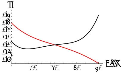
[image:4.612.326.529.88.215.2]From equation (3) L1 (cycles to failure of the first load step) for the “heavy duty” PSRU (Table-2) is already larger than 1010 cycles. In addition, load step 2 of “heavy duty” aircraft is verified in the same way. With this level of torque double helical gears are the best choice. However, the helix angle should not exceed 30° (Figure-1).
Figure-1. SF for pitting (Red) and for Strength (black) with helix angle (Beta).
Figure-1 shows the Safety Factor (SF) for pitting (Red) and for strength (Black) with the helix angle Beta for cylindrical-helical pinion.
As it can be seen, the best compromise is between 20 and 30°. The gear drive of Figure 1 had a mesh of 13/141, a transverse pitch of 2.94, a normal pressure angle of 20° and a face width of 100mm. For aircraft PSRU, the designer should start with an angle of 20°. In case of problems, it is possible to improve strength by increasing the helix angle. Pitting in aircrafts is not a common problem and can be solved by reducing TBO or by working on lubrication and cooling.
Helicopter gearing
In helicopter transmissions, breakage is the less critical of the four main failure modes: wear, plastic flow, surface fatigue, and breakage [7] [8] [9]. This is because helicopter transmission maximum torque is always limited. In fact, the enormous inertia moment of the rotor requires a decoupling joint for the engine. While turbo shaft are gas coupled to the free turbine, piston engine requires a proper decoupling and damping device. Typically, centrifugal clutches, belts and springs are uses for this purpose. In piston powered helicopters, a mechanical over torque device is always present. Therefore, a maximum torque value is guaranteed. In a few designs (mainly western designs) the torque is limited by a torque limiter on the fuel flow, in other, (Russian designs) the maximum torque is limited by the turboshaft efficiency. Therefore, the maximum transmissible torque is known. For large automotive engines, like trucks and heavy duty vehicles, torque converters are used for the decoupling purpose. This solution is the best also for helicopters, with a proper tuning of the converter stall speed. The helicopter gearing design focuses on the surface fatigue class of failure, which is characterized by the removal of metal and the formation of cavities. These cavities may grow or go into remission. Repeated stresses beyond the endurance limit of the metal make the gear material fail. Surface fatigue may be classified into four modes: micro pitting, pitting, spalling and destructive pitting. Micropitting engraves on the surface very small micropits, usually below 0.0001 inches deep. This is often an indication of lubrication problems. If the marginal lubrication condition persists, these micropits grow and
10
20
30
40
Beta
merge with others, producing larger cavities. Therefore, it becomes pitting. In this case, the cavities have a diameter between 0.015” and 0.030” inches in diameter. Pits always occur in over-stressed parts of the gear teeth. Corrective pitting tends to redistribute the load by progressively removing high pressure contact spots and often stops once the load has been redistributed. This happens typically during the run-in. When the pits continue to grow the phenomenon is called spalling. A customary dividing line between spalling and pitting is a pit diameter of 0.030 inches. As a spalled tooth meshes, the absent portion of the tooth surface does not carry the load. This results in a large stress concentration around the pit’s edges. These stresses lead to accelerated material removal, resulting in further spall. This phenomenon increases vibration levels because the impulsive effect can excite previously dormant modes of the transmission. All these damages are linked to poor, improper lubrication and thermal overload. On the contrary, overload (mechanical and thermal) or undersizing is the cause of Destructive Pitting. This fault appears as larger pits in the dedendum section of the gear teeth. These larger craters usually are caused by more severe overload conditions and are characterized as size does not stabilize. As stress cycles build up, spalls whose destructive pitting destroys the tooth profile and takes up a considerable percentage of the tooth face. It is not possible, just from an inspection, to discriminate spall from destructive pitting. Often, in helicopters, the worst condition is loss-of-lubricant test. This certification test is carried out by simulating a loss of lubricant on the main gearbox by draining the gearbox and using only the remaining residual oil. Then gearbox operation continues in accordance with the requirements of AC 29-2C. The purpose of this test, outlined in the test documentation, is to demonstrate that the transmission can provide “continued safe operation for a minimum of 30 minutes following a complete loss of lubricating oil in accordance with the requirements of FAR 29.927(c).” This test is extremely critical due to absence of the cooling provided by the lubricant. Temperatures rise well over normal levels and steel faces a reduction of hardness and strength. Continuous improvements and tests are made by steel companies to improve temperature resistance. The main difference between carburized steel 1 and 2 of Table 6 is residual strength at high temperature. Nitrided gears are slightly better from this point of view, but the lower hardness tends to reduce gear life in normal conditions. However, modern helicopter bearings are manufactured with nitrided steel. Even standard gearing lubrication is critical. Concentrated load-transmitting contacts such as gear teeth have surfaces that do not conform to each other, so small, lubricated areas must then carry the load. The lubrication area of a non-conformal conjunction is typically three orders of magnitude less than that of a conformal conjunction like journal bearings. In general, the lubrication area between non-conformal surfaces enlarges considerably with increasing load, but it is still smaller than the lubrication area between conformal surfaces. Gear tooth contacts are still one of the most complicated applications of tribology. Therefore, practical
experience in gear design is still fundamental. These lubricated contacts are often referred as Elasto-Hydrodynamic Lubrication (EHL). Elasto-Hydrodynamic film thicknesses in this regime range from 0.025 to 1.250 µm. The gear manufacturing processes tend to leave relatively rough surfaces so that the oil films, generated by the EHL action, are thin compared to the height of roughness asperities present on the mating teeth. For example, typical high quality ground gears currently used in aerospace applications have teeth with a roughness average (Ra) of 0.4 µm, giving peak to valley dimensions of about 2 µm. Under the most favorable conditions of load, speed, and temperature, the lubricant film is about 1 µm for such gears, but much thinner films are common at low speeds or at high temperatures. It is therefore clear that the majority of gears operate in a lubrication regime in which there is significant interaction between the surfaces within a film the size of the asperities. From the kinematic relations of gears, the rolling and sliding velocities can also be determined. Theoretically, with this input data, one can determine the lubrication performance of the gears using recent EHL theories. However, there are concerns about thetrue location of the areas of very thin film thickness and the true sizes of these films. Consequently, it is difficult to individuate the location of the areas of very high surface contact temperatures that can initiate scuffing and to calculate these contact temperatures. Practically, lubricants include highly-resistant adhesive-additives that strengthen the resistance of the oil film. Furthermore, anti-seizure additives are added to avoid metal direct contact and seizure. These additives minimize frictional forces between moving surfaces, create a surface active film via polar and non-polar ends and forms a layer that provide lubricating effects. In high temperature environments, with high temperatures and high contact stress, these lubricant tend to deteriorate rapidly. Therefore, lubricant monitoring is fundamental. In gearing EHL the pressure between contact surfaces is very high so that the contact surfaces deform elastically to an amount comparable to the film thickness. Unlike hydrodynamic lubrication where the expression for the film thickness can be determined a priori, in EHL problems the pressure distribution and the film thickness should be determined simultaneously. In point contact EHL; the contact takes place within a finite “elliptical” region. As the gear pitch line velocity increases, the pressure peaks decrease, and the film thickness increases significantly. The differences in the pressure distributions are not significant, but there are significant differences in fluid film thickness distribution. For example, a two-fold increase in speed increases the film thickness by 50%. Large velocities do not significantly influence the surface temperature distribution.
maximum. In equation (8) u1 and u2are the maximum surface speeds of pinion and gear respectively.
2
2 1
2 1
u u
u u SR
(8)
As SR changes from 0.1 to 0.5, the fluid temperature in the contact zone increases 3-folds. Therefore, large increases in the surface temperature are obtained if SR increases, for both the temperature in the contact zone and the temperature at the exit of the contact zone.
Bevel spiral helicopter gearing
The most common spiral bevel normal pressure angles are within 16° and 20°, with the latter now being standard. Angles between 20.5° and 25° are more often used in highly-loaded high-speed helicopter transmission. As the pressure angle increases the spiral angle decreases. For the normal pressure angle of 20° the most common spiral angle is 35°. With larger pressure angles, the spiral angles decrease from 25° down to 15°. The profile contact ratio on all bevel gears is substantially lower than equivalent spur gears. This fact makes bevel gear noisier. In addition, efficiency is lower due to the higher total load for a given tangential load and substantially higher sliding velocity. Therefore, the efficiency of spiral bevel gears is rarely higher than 99.2%. For comparison, the efficiency of spur gear may reach 99.75%, while the efficiency of helical gear can arrive at 99.85%. The more common spiral bevel gears are the “Gleason” ones, from the Company that manufactures the grinding machine. These are the circular-lengthwise tooth-curvature bevel gears. These gears are cut with face-milled cutters with multiple blades. Spiral bevel gears are can reach pitch line velocity of more than 160m/s.Due to the restrictive pitch line velocity and the small contact area the straight bevel gears are not feasible for helicopter drive systems, while face gears are still in development. Face gears are convenient for 90° split torque transmission, where spiral bevel gears are difficult to use. The three dimensional curve of spiral bevel gears generates three-dimensional loads on bearings. For this reason, bevel gears are used in the low-torque
high-speed part of the transmission system, leaving the high torque low-speed high-reduction-ratio part to planetary gearings. Double helical planetary gearing easily reach efficiencies up to 99.7% with a lowest worn-out point down to 99.5%.
Usually bevel gearing are calculated with the AGMA method, while the best correction method comes from the Merrit’s book [10]. For manufacturing easiness and cost effectiveness, the best normal pressure angle is 20°. In addition, the most common spiral angle is 35°.AGMA recommends higher values than 2.0 for the face contact ratio for smooth and quiet operation, or high speed applications. The AGMA equation for face contact ratio Crf is (9).
tan
0 do sm rf
b
p
A
A
C
(9)Where A0 and Am are the outer cone and mean cone distance. Pdo is the transverse diametral pitch. Bw and φ are the net face width and the spiral angle.
Face contact ratios below 2.0 are unadvisable. Contact ratios larger than 2.0 generally reduce the gearing efficiency. The safety factor for pitting is 2.0 with the maximum effective torque (Table-4). For bending (strength), the maximum transmissible torque should be used. Also for strength, the minimum safety factor is 2.0. Spiral angle should be reduced as pressure angle increases. A contact ratio around Crf of2.0-2.2 should be considered a good criterion for efficiency. A 20% reduced addendum is also advisable to keep SR low and to reduce scuffing probability. For backlash regulation, the unloaded gear-tooth contact should initiate from the small end and extend to approximately75%of toothlengthtowardthelargeend. Chamfered or rounded tooth edges are not convenient. Profile correction for load is necessary and can be obtained with a brief run-in under design load with annealed steel gears (material 3 of Table-6 without nitriding).
Flash temperature calculation is also fundamental. Table-7 shows allowable flash temperatures for the materials of Table-6.
Table-7. Maximum Flash Temperature °C.
Material Mil-L-2105 with EP 90 with
1 Carburised Steel Ferrium C69 440 770 2 Carburized Steel AISI 9310 343 649
3 Nitrided Steel
AISI E4340 Mod (AMS 6419) 450 800
From reference [11], a simple equation for flash temperatures Tf(Fahrenheit) above the bulk operating temperature is (10).
3125 . 0 6875 . 0 75 . 0
291
.
1
GW
S
P
n
Where G is the geometry factor, W is the load factor that depends on torque, gear quality and operating speed.
s
S
50
50
(11)
In equation (10) s is the average roughness (μinch). P is the diametral pitch (inch) and n is the pinion speed (rpm). The number of Tf obtained is only to validate the design and it is not a true temperature value. Therefore, the “flash temperature number” is a tool of comparison with already proven designs. Load, diametral pitch, pinion rotational speed and roughness are critical for flash temperature. Therefore, it is important to obtain the best roughness value possible. In fact, the other parameters are difficult to vary. For this purpose, run-in is particularly important.
CONCLUSIONS
Aerospace gearing is sized on bending fatigue, surface compression/lubrication (Hertz stress) and scuffing resistance (Flash temperature). A correct design method should include adequate ability to resist all these types of failures. On aircraft PSRU the tooth bending is most critical, whereas pitting and scuffing are durability-type failures that can be (theoretically) anticipated and corrected before final failure. On the contrary, helicopters are more critical for scuffing and pitting. However, it is important for the designer to understand the criticalities of the different applications. This fourth part deals with aerobatic/racing/STOL-utility “heavy duty” aircrafts. Typical load histories for general aviation/heavy-duty aircrafts and helicopters are detailed with an example. A practical method to verify whether a PSRU for general aviation is verified also for a “heavy duty” aircraft is introduced. Criteria for helicopter transmission design and advanced material data are also included in this paper. New data on flash temperature of bevel gears are also introduced. Gear type selection and general transmission design criteria are also introduced.
REFERENCES
[1] L. Piancastelli, L. Frizziero, E. Pezzuti. 2014. Aircraft diesel engines controlled by fuzzy logic. Asian Research Publishing Network (ARPN). Journal of Engineering and Applied Sciences”, ISSN 1819-6608, 9(1): 30-34, EBSCO Publishing, 10 Estes Street, P.O. Box 682, Ipswich, MA 01938, USA.
[2] L. Piancastelli, L. Frizziero, E. Morganti, A. Canaparo. 2012. Fuzzy control system for aircraft diesel engines, International Journal of Heat and Technology, ISSN 0392-8764, 30(1): 131-135.
[3] L. Piancastelli, L. Frizziero and I. Rocchi. 2012. Feasible optimum design of a turbo compound Diesel
Brayton cycle for diesel-turbo-fan aircraft propulsion. International Journal of Heat and Technology. 30(2): 121-126.
[4] L. Piancastelli, L. Frizziero, N.E. Daidzic, I. Rocchi. 20136. Analysis of automotive diesel conversions with KERS for future aerospace applications. International Journal of Heat and Technology, ISSN 0392-8764, 31(1).
[5] L. Piancastelli, L. Frizziero, E. Pezzuti. 2014. Kers applications to aerospace diesel propulsion. Asian Research Publishing Network (ARPN). Journal of Engineering and Applied Sciences. ISSN: 1819-6608, 9(5): 807-818, EBSCO Publishing, 10 Estes Street, P.O. Box 682, Ipswich, MA 01938, USA.
[6] L. Piancastelli, L. Frizziero, I. Rocchi. 2012. An innovative method to speed up the finite element analysis of critical engines components, International Journal of Heat and Technology, ISSN 0392-8764, 30(2): 127-132.
[7] L. Piancastelli, L. Frizziero, G. Zanuccoli, N.E. Daidzic, I. Rocchi. 2013. A comparison between CFRP and 2195-FSW for aircraft structural designs. International Journal of Heat and Technology, ISSN 0392-8764, 31(1): 17-24.
[8] L. Piancastelli, L. Frizziero, E. Morganti, E. Pezzuti. 2012. Method for evaluating the durability of aircraft piston engines. Walailak Journal of Science and Technology, ISSN 1686-3933, 9(4): 425-431.
[9] L. Piancastelli, L. Frizziero, G. Zanuccoli, N.E. Daidzic, I. Rocchi. 2013. The "C-Triplex" approach to design of CFRP transport-category airplane structures. International Journal of Heat and Technology, ISSN 0392-8764, 31(2): 51-59.
[10]H.E. Merrit. 1975. Gear Engineering SBN 10: 0470596279 - ISBN 13: 9780470596272 - John Wiley and Sons Inc, N.Y.