International Journal of Emerging Technology and Advanced Engineering
Website: www.ijetae.com (ISSN 2250-2459, ISO 9001:2008 Certified Journal, Volume 6, Issue 12, December 2016)
Energy Efficient Smart Tubelight Technology
Apurv Agrawal
1, KM Garima Mishra
2, Sumit Kumar Verma
3, Padma Batra
4 1,2,3,4Electronics and Communication, KIET Ghaziabad, India
Abstract— Several kinds of lamps have been developed
since Thomas Edison patented his incandescent bulb in 1879 and after a year in 1880, he began to commercialize his bulb. Different lamps have different aspect in terms of voltage, current, performance, size, temperature, color and etc. There is a need to carefully utilize the available energy resources as the energy crisis is increasing day by day. The need of energy can be met by different ways by conversion of waste to useful energy, using non conventional energy resources and etc. Energy conservation is always preferred over the energy generation. There is always a need to make the device efficient and energy-saving than its previous version. This paper deals with change in the design of the back frame of the fluorescent tubelight which results in conversion of waste to useful energy. The conventional fluorescent tubelight is available with white flat back supporting frame. The various changes have been made in the past and still continuing in design of conventional tube or tube holder to make it efficient and better in appearance. The modification discussed in this paper provides some exceptional features in the existing design of tubelight frame. This would increase the amount of light (lux or lumens/m2) reaching to the destination after getting
reflected from the modified frame in the same power consumption. The new design will enhance energy conservation.
Keywords—NI LabVIEW, Wireless Sensor Network, LDR energy, tubelight, reflector, efficiency
I. INTRODUCTION
A wide range of rules and regulations must be kept in mind before the designing of lighting solutions. In present time different types of lighting devices with different designs are used. The device‟s design and power consumption varies according to the need and the place of its usage for example- Industries, offices, schools, house etc.
Out of all lighting devices fluorescent tubelight are widely used because of their low power consumption and homogenous distribution of light. In the fluorescent tubelight when the voltage is applied across its terminals, it creates an electric current between electrodes i.e. cathode and anode which are placed at either end of the fluorescent lamp. This current energies the mercury atoms. These energized mercury vapors delivers ultraviolet photons that is invisible to the human eye. There is phosphor coating on the inner walls of the glass tube. When these photons react with this coating, they began to radiate visible light photons. The color of the visible light can be changed from cool to warm by changing the material of the coating.
The ballast regulates the current and provides the sufficient voltage. [1]
Consideration of amount of functional light is different for different area either in terms of energy expended or in terms of aesthetic value. Sports facilities require appropriate light for the task. Office buildings require energy-saving lightning system, whereas theaters and casinos have a major to do with the architecture through lighting systems. Designing of the lightning system should have a concern with the daylight and the energy-saving mode. [2]
This results in that illumination of any buildings or spaces has the following fundamentals:
Aesthetic appeal of a building The ergonomic aspect Energy efficiency issue
Each of these aspects is considered by the designer. This paper is especially concerned with the last aspect that is the energy-efficiency issue. [2]
Table 1:
Luminous Efficacy Of Different Light Sources [3]
[image:1.595.310.555.670.756.2]In the above Table:1luminous efficacy of different light sources are mentioned. The following parameter such as Luminous efficacy and the light source are given their corresponding column.
Table 2:
Iesna Standard Lighting Requirements [4] Light source Luminous efficacy
(lumen/watt)
Light source
Incandescent light
18-20 Incandescent light
Fluorescent light
60-70 Fluorescent light
Sodium Vapour
40-120 Sodium Vapour
Mercury Vapour
50-60 Mercury Vapour
Metal Halide 80-125 Metal Halide
CFLs 50-80 CFLs
S. No. Location Lighting Power Density(wt/ft2)
1. Manufacturing 1.3
2. Office 1.1
3. Warehouse 0.8
International Journal of Emerging Technology and Advanced Engineering
Website: www.ijetae.com (ISSN 2250-2459, ISO 9001:2008 Certified Journal, Volume 6, Issue 12, December 2016) In the above table:2 the location of and the lighting
devices and lighting power in wt/ft2 is mentioned. Manufacturing spaces requires high lighting power density while warehouse requires the least.
II. WORKING PRINCIPLE
A. Reflection
Reflection is the process of change in direction of a wavefront at an interface between the two different media so that the wavefront returns into the medium from which it was originated. Examples - reflection of light, sound and water waves. According to the law of reflection, for specular reflection the angle at which the wave is incident on the surface equal to the angle at which it is reflected. [5]
B. Diffraction
Diffraction is the phenomena in which a wave encounters an obstacle or a slit which results in bending of light around the corners of an obstacle into the region of the geometrical shadow of the obstacle. This property of wave is exhibited when a wave encounters an obstacle that is comparable in size to its wavelength. [6]
C. Absorption
[image:2.595.315.547.249.364.2]Absorption is the phenomena in which the energy of a photon (of electromagnetic radiation) is taken up by matter, typically the electrons of an atom. So, the electromagnetic energy is transformed into the internal energy of the absorber, example-thermal energy. [7]
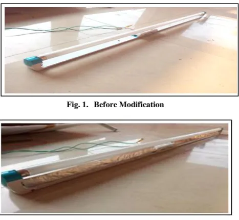
Fig. 1. Before Modification
Fig. 2. After Modification
III. EXPERIMENTAL DESIGN
In this technique, the design of back frame of tubelight has been modified to increase the amount of light or the luminous intensity (lumens/m2 or Lux) reaching to the destination. Light Intensity from different shapes (parabolic, straight triangular etc) of the reflector has been experimentally tested. The best result comes out with the triangular shape reflector with its sides slightly curved inwards.
Fig. 3. Designed Triangular Reflector
The back frame is designed in a triangular shape with its edge towards the tube. The edge width is kept very small so that the back and forth reflection will reduce to almost zero as the surface has been reduced. The frame has silver coating over its surface to provide a better reflection of light with minimum absorption and width of edge is kept very small.
[image:2.595.51.285.484.699.2]In the modified design the light emitted from the upper half cylindrical portion of the tube directly reaches to the destination. But the light emitting (in cylindrical wavefront) from the back half cylindrical portion of the tube in Fig: 4 that is facing towards the edge of the triangular frame strike onto the silver coated side planes of the triangular reflecting sheet and get reflected back towards the destination and its surroundings.
[image:2.595.312.548.554.686.2]International Journal of Emerging Technology and Advanced Engineering
[image:3.595.44.280.141.284.2]Website: www.ijetae.com (ISSN 2250-2459, ISO 9001:2008 Certified Journal, Volume 6, Issue 12, December 2016)
Fig. 5. Process of Emission and Absorption Before Modification
The above modification in the design of back supporting frame results in maximum transfer of light to the destination while in the previous design involving white flat supporting frame in Fig: 5, the light which comes from the back half cylindrical portion of tube is being absorbed in white frame and then emits towards the same back half cylindrical portion of the tube.[8] This process is continuous which results in the trapping of light during the multiple reflections between the tube and its back frame. The modification in design removes the trapping of light that results in efficient use of waste energy.
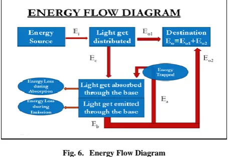
[image:3.595.317.544.230.403.2]According to the energy flow diagram in Fig:6 Ei is the energy that is given to the fluorescent tubelight which get distributed in the surrounding in from of its luminescence.
Fig. 6. Energy Flow Diagram
Most of the light energy reaches to the destination Eo1 . But some part of light emitting from the back portion of the tube which interacts with the back supporting fame is Ec. This light get absorbed and some absorption losses occur and after that light get emitted and some emission losses occur. Some part of light Ea is trapped in multiple reflection process as discussed above and rest part E02 is moves out to surrounding after suffering absorption and emission losses.
The modification in design is tested with the help of an experimental setup which consists of a fluorescent tube light, a circuit consisting of National Instruments WSN (wireless sensor network) node [9], an LDR (light dependent resistor), a resistor of a 10k ohm and a constant DC power source of 5 Volt (as shown in figure 7). The LDR changes its resistance with respect to the intensity of light of the fluorescent tube.
Fig. 7. Experimental Setup
For the precise observation, the whole system is placed in a dark room on the wooden table. The voltage drop across the LDR was fed into WSN node which is connected through a router to the PC having NI LabVIEW software. The terminals of LDR was connected to to the pin AI0 (+ve) and GI0 (-ve) or ground of WSN (node 3202). A proper VI (virtual instrument) as shown in figure 4 is designed in NI LabVIEW that converts the LDR voltage drop into the resistance of LDR and then finally to lux (lumen/m2).
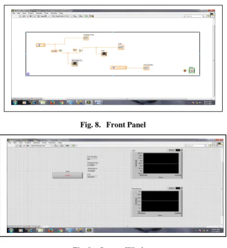
Figure 8 shows the block diagram of the VI. The voltage across the LDR has been multiplied to the calibrated constant i.e. 4.5169 to obtain the corresponding resistance across the LDR. A Multimeter was used to find the calibration constant. Further this resistance has been divided by the constant 500 using the standard formula and this division gives the luminous intensity or lux of the tube. [10]
Lux (Lumens/m2) = 500/R R= Resistance of LDR
The whole block diagram is in a while loop for the continuous output. A block of „link quality‟ in the diagram shows the quality of the link between the node and the router.
The output has been shown in the figure 8 i.e. is the front panel. It has a stop button for stopping the while loop, numeric value of the link quality, voltage drop, resistance and the lux. The graph of the luminous intensity (Amplitude v/s time) and the resistance
[image:3.595.50.280.500.657.2]International Journal of Emerging Technology and Advanced Engineering
[image:4.595.48.281.130.384.2]Website: www.ijetae.com (ISSN 2250-2459, ISO 9001:2008 Certified Journal, Volume 6, Issue 12, December 2016)
Fig. 8. Front Panel
Fig. 9. Output Window
IV. RESULT AND DISCUSSION
Modification in the design of the tube light back frame results in increased amount of light reaching to a destination with the same power consumption. The other type of the reflectors is also available but they are not as efficient as we have embedded. The ballast is hidden in tube light frame in the new design. The design modification can be done most of the tube light assembly. Also, the triangular frame can be easily placed in the tube lights which manufactured already with no modification in design.
The number of readings was taken by varying the distance of LDR from the tube light. R1 is the resistance of LDR without modification in design. R2 is the resistance of LDR after modification in design. L1 is the luminous intensity without modification in design. L2 is the luminous intensity after modification in design.
Table 3 given below shows the comparison between the intensity of tubelight with conventional fixture and the new designed fixture. The number of observations were taken by varying the distance of LDR from the tube light. The first column of table 3 shows the distance of LDR from the tube in centimetres. The adjacent column is of R1 that is the resistance of LDR without modification in design of the back frame. L1 is the luminous intensity in Lux (lumen per square meter) without the modification in design.R2 shows the resistance of LDR after the design has been modified. The last column of the table shows L2 that is the luminous intensity in Lux after modification in design.
[image:4.595.306.561.192.560.2]Table 4 shows the comparison in features of the conventional design and modified design of the back frame, for example in aesthetic value as well as in the brightness.
Table 3: Comparision Between Lux
S.NO Distance
(cm)
R1 (ohm)
L1 (lux)
R2 (ohm)
L2 (lux)
1. 0 451 1342 404 1554
2. 5 636 849 618 882
3. 10 832 593 797 628
4. 15 1002 463 962 489
5. 20 1176 374 1116 401
6. 25 1333 316 1267 339
7. 30 1496 271 1423 290
8. 40 1806 211 1716 226
9. 50 2.12k 170 2.02k 182
10. 60 2.46k 140 2.36k 148
11. 70 2.84k 115 2.77k 119
12. 90 3.61k 84 3.51k 87
13. 110 4.45k 63 4.29k 67
Table 4: Comparision
S.NO Conventional Design Modified Design
1. Less Intensity High Intensity
2. Flat back frame Triangular back frame
3. No reflecting coating only white paint. A frame having a reflecting coating.
4. Ballast mounted outside Ballast fitted inside.
V. CONCLUSION AND FUTURE SCOPE
The modification is very simple and cost effective as it involves a change only in shape without increasing the amount of material used at manufacturing level and only a small cost of reflecting coating is required.
Also any existing user can put the triangular reflector in the gap present between the tube and the back frame.
International Journal of Emerging Technology and Advanced Engineering
Website: www.ijetae.com (ISSN 2250-2459, ISO 9001:2008 Certified Journal, Volume 6, Issue 12, December 2016) The integration of daylight with the tubelight light
energy is another feature that will be provided. That means it will have the intensity variation feature. This feature will work accordingly to the availability of daylight if the daylight is in fewer amounts, the intensity of the tube light will increase and if the daylight is in sufficient amount the tube light will provide the lumen/mt2 for which it is designed. By providing such a feature to it the existing tube light will become smart and also become popular in the market.
REFERENCES
[1] Lokendra Pal Singh,GoldyKatal, “A Comparative Study on
Design and Operation of Fluorescent Lamps, Cfls and Leds, Journal of Engineering Research and Applications,Vol. 3, Issue 5, Sep-Oct 2013, pp.401-407
[2] P. Mukherjee, "An Overview of Energy Efficient Lighting System
Design for Indoor Applications of an Office Building", Key Engineering Materials, Vol. 692, pp. 45-53, 2016
[3] Biswajit Biswas, Sujoy Mukherjee and Aritra Ghosh,
Conservation of Energy: a Case Study on Energy Conservation in Campus Lighting in an Institution, International Journal of Modern Engineering Research (IJMER), Vol.3, Issue.4, Jul - Aug. 2013, pp-1939-1941, ISSN: 2249-6645
[4] EnergyCodes.gov, “ANSI/ASHRAE/IESNA Standard 90.1-2007:
An Overview of the Lighting and Power Requirements,” January 2008. http://www. energycodes.gov/training/pdfs/lighting07.pdf
[5] Lekner, John (1987). Theory of Reflection, of Electromagnetic
and Particle Waves. Springer. ISBN 9789024734184.
[6] Copyright Holder-Springer Verlag Berlin Heidelberg, Wave
Physics, Publisher-Springer Berlin Heidelberg,,
Copyright-2009,DOI-10.1007/97835408790845,
Print-ISBN-9783540879077,Online-ISBN-9783540879084
[7] Craig F. Bohren and Donald R. Huffman, Absorption and
Scattering of Light by Small Particles, ISBN: 978-0-471-29340-8
[8] P.U.P.A. Gilbert and Willy Haeberli, Physics in the Arts: Revised
Edition (Complementary Science), , 13 Jul 2011, Imprint:
Academic Press, Print Book ISBN : 9780123918789, eBook ISBN : 9780123918895
![Table 2: Iesna Standard Lighting Requirements [4]](https://thumb-us.123doks.com/thumbv2/123dok_us/8688808.876628/1.595.310.555.670.756/table-iesna-standard-lighting-requirements.webp)