Effect of Front and Back Suppressing Vibration on
Actuation Waveform Design of DoD Inkjet Printer to
Droplet Speed and Volume
Oke Oktavianty1,*, Shigeyuki Haruyama2, Yoshie Ishii2, Zefry Darmawan1
1
Universitas Brawijaya, Indonesia
2
Yamaguchi University, Japan
Received April 26, 2019; Revised October 1, 2019; Accepted December 23, 2019
Copyright©2019 by authors, all rights reserved. Authors agree that this article remains permanently open access under the terms of the Creative Commons Attribution License 4.0 International License
Abstract
One of the operational issues that are generally encountered on the print-head performance is residual vibration. For good performance of droplet, the satellite and ligament of an ink droplet must be suppressed during the jetting process. It was proved that the suppressing vibration is viable to control the droplet’s speed and volume. Two kinds of suppressing vibration with front and back position of suppressing pulse from the main pulse were investigated. The suppressing vibration was proved to be an effective way of damping the residual vibration and reducing the droplet volume and speed. By analyzing two types of actuation waveforms effect on droplet quality, this paper analyzes the distinctive effect of front and back suppressing vibration on droplet quality.Keyword
Suppressing Vibration, Actuation Waveform, DoD, Inkjet Printer1. Introduction
The inkjet printer quality is strongly related to the print-head performance. The performance of an inkjet print-head is limited by residual vibrations, cross-talk and jet instability that will generate the droplet with ligament, satellite or even weeping, particularly in multi-drop ejection method. The properly waveform design can minimize those both cross-talk and the residual vibrations [1] & [2].
For enhancing the inkjet printer performance, we have to consider the following operational issues that are associated with the waveform design and operation of nozzle heads. The droplet and satellite can be eliminated by optimizing the waveform design. The basic waveform itself was proved not to generate a clear droplet if it is
applied without additional pulse. The satellite on droplet and ligament of an ink droplet can be suppressed during the jetting process. It was stated that the performance of Drop on Demand (DoD) inkjet printer is mainly affected by residual vibration occurrence [3] - [8]. The residual vibration and crosstalk influence each other, particularly in high drop repetition rate. This problem can cause a very large difference in droplet speed [9] & [10]. The actuation waveform of the piezoelectric element has a strong influence on the droplet ejection process, controlling both the size and velocity of the ejected droplets [11]. For reducing the residual vibration that caused satellite, the actuating waveform to eject the droplet must be properly designed [1], [4], [12] & [13]. In this study, the effect of different actuation waveform design with front and back position of the suppressing vibration was investigated by the experimental study. The waveform design with suppressing vibration that could generate the droplets with a good shape will be considered as the recommended waveform design.
2. Operational Issue of PIJ Print-head
The operational issues that generally deal with the performance of inkjet print-head [3] - [7], are namely: 1. Residual vibrations
Universal Journal of Mechanical Engineering 7(6B): 12-18, 2019 13
also influenced by cross-talk effects. Both residual vibrations and cross-talk can result in the variation of droplet speed on each nozzle [14] & [15].
2. Cross talk in piezo-inkjet
The cross-talk takes place when the neighboring nozzle is influenced by another channel actuation. The unintended ejection exists due to the disturbing resonances in the print-head structure. It also causes a difference in droplet speed and weeping occurrence. The existence of residual vibration and crosstalk will give significant effects in the ink chamber [7]. Therefore, in this study, the additional pulse will be applied to the basic waveform to suppress the effect of both residual vibration and the cross-talk.
3. Research Method
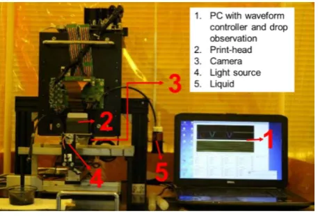
[image:2.595.309.537.385.641.2]The observation system GEN 5 on a personal computer was used to input the optimized waveform design. The signal was sent to the print-head to eject the droplet from the nozzle. The print-head type was GEN 5 with piezoelectric type D33 that was installed in PC. The droplet image was obtained by shadowgraph technique. The droplet image was taken by Charged Coupled Device (CCD)camera that is equipped with iDS Complementary Metal Oxide Semiconductor (CMOS) sensor and strobe lights. The CCD camera, CMOS sensor and stroble light were synchronized to the firing signal. The delay time of droplet to reach 1 mm from the nozzle and the droplet image will be displayed in the PC at drop watch form. The experimental equipment is shown in Fig. 1.
Figure 1. Experimental Equipment
In this section, the effect of suppressing vibration pulse was investigated when it is located prior to or after the
main pulse. In this study, the comparison of experimental result between the basic waveform or one main pulse was compared with two types of actuation waveform with additional suppressing pulse. The observation was conducted on the droplet speed and volume of a single droplet from one main pulse. Figure 2a depicts the waveform design with suppressing vibration that was located after main pulse, meanwhile the figure 2b shows that the suppressing vibration was placed prior to the main pulse.
There are two kinds of waveform design with the different parameters of time for down, keep, up and wait. The suppressing pulse with suppressing pulse parameter of time for down, keep and up = 2 µs called as Suppress A. In another side, the suppressing pulse parameter of time for down, keep and up = 1 µs called as Suppress B. The suppressing pulse that was located after the main pulse was so-called back suppressing vibration, whereas this section used the actuation waveform with suppressing vibration that was located before main pulse, hereafter called as front suppressing vibration. The experimental study to investigate the droplet speed and volume was conducted. The waveform design with suppressing pulse as compared to the basic waveform, The basic waveform’s parameter is shown in Fig. 3.
Figure 2a. Suppressing Pulse Profile (back)
Main Pulse: t
down= t
keep= t
up= 2µs
t
wait= 6 µs
Suppressing Pulse: t
down= t
keep= t
up= 2µs
(Voltage: 30%, 50%)
Main Pulse: t
down= t
keep= t
up= 2µs
t
wait= 0 µs
Suppressing Pulse: t
down= t
keep= t
up= 1µs
(Voltage: 30%, 50%)
[image:2.595.61.290.474.629.2]
Figure 2b. Suppressing Pulse Profile (front)
Figure 3. Basic waveform
[image:3.595.60.288.82.379.2]4. Result and Discussion
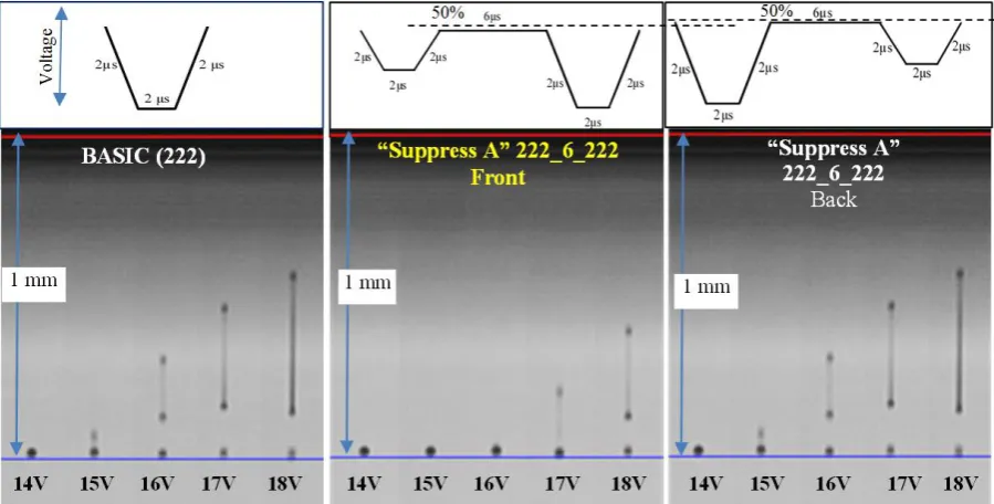
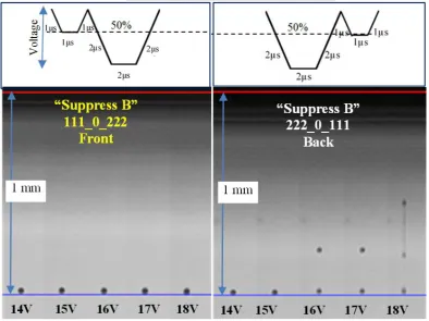
Figure 4 presents the droplet shape comparison of front and back suppressing vibration with basic waveform. The droplet shape from waveform design with different locations of suppressing pulse was observed. We can see the similar droplet shape for basic waveform and back suppressing waveform of “Suppress A”. Front “suppress A” generated the clear droplet at applied voltage 14 – 16 V and droplet with ligament at 17 – 18 V. The comparison of front and back “Suppress B” shows that the clear spherical droplet was generated at 14-15 V only for back “suppress B”, whereas front waveform generated clear droplet at all applied voltages. It expresses that we are able to get the higher speed of droplet with a clear shape for obtaining good print quality.
[image:3.595.353.489.95.191.2] [image:3.595.73.523.441.669.2]Universal Journal of Mechanical Engineering 7(6B): 12-18, 2019 15
[image:4.595.137.456.407.626.2]Figure 4. The droplet shape comparison between basic waveform with front and back suppressing vibration (voltage of tkeep = 50%)
Figure 5. The droplet velocity comparison between basic waveform with front and back suppressing vibration (voltage of tkeep = 50%)
The droplet shape is related to the droplet velocity particularly for back suppress A vibration, as shown in Figure 5. The figure shows that those waveforms also have similar velocity, with a similar trend to back suppress B vibration. The front suppress A and B have similar velocity trend with smooth linearity, but in lower velocity. It also
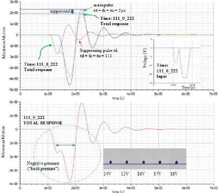
Figure 6. Conceptual model for “Front Suppress B” (111_0_222)
Figure 6 depicts that front “suppress B” (111_0_222) vibration has a different response than the others. The small pulse before the main pulse without separating time as well as preliminary vibration composes the wider negative pressure. It indicates that the “pull” mode of PZT (piezoelectric) print head plays a role in sucking the liquid thread into the liquid chamber so it will take a longer time for ejection and the volume inside the nozzle become larger. By the additional pulse on the waveform design as a preliminary vibration, will evoke the Helmholtz resonance inside the liquid chamber. Since the energy that used to “push” the ink out from the orifice is identical, consequently, the droplet velocity will be slower. This result then recommended being used for the next step in designing the actuation waveform for multi-drop method.
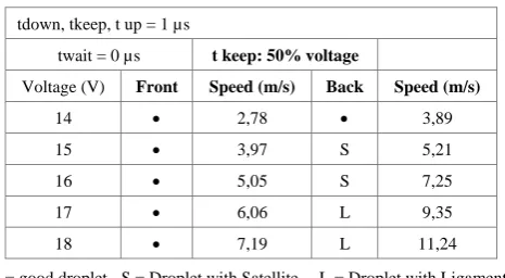
Table 1 until table 3 expressed the comparison of each waveform design, namely suppress A and B with different percentages of voltage on tkeep. It was clearly shown from
the tables that the best droplet shape with the highest speed will be generated from the waveform design namely suppress B. The best percentage of tkeep was 50% from the main voltage, e.g. 7 Volt for applied voltage 14 volt of the main pulse.
Table 1. Experiment result of Suppress A (50% voltage of tkeep)
tdown, tkeep, t up = 2 µs
twait = 6 µs t keep: 50% voltage
Voltage (V) Front Speed (m/s) Back Speed (m/s)
14 • 2,27 L 6,41
15 • 1,49 L 8,06
16 • 1,25 L 9,90
17 L 3,07 L 11,76
18 L 4,24 L 13,70
[image:5.595.70.513.82.473.2]Universal Journal of Mechanical Engineering 7(6B): 12-18, 2019 17
Table 2. Experiment result of Suppress A (30% voltage of tkeep)
tdown, tkeep, t up = 2 µs
twait = 6 µs t keep: 30% voltage
Voltage (V) Front Speed (m/s) Back Speed (m/s)
14 • 5,00 L 6,41
15 L (short) 5,95 L 8,00
16 L 7,14 L 9,90
17 L 8,33 L 11,76
18 L 9,71 L 13,70
• = good droplet S = Droplet with Satellite L = Droplet with Ligament
Table 3. Experiment result of Suppress B (50% voltage of tkeep)
tdown, tkeep, t up = 1 µs
twait = 0 µs t keep: 50% voltage
Voltage (V) Front Speed (m/s) Back Speed (m/s)
14 • 2,78 • 3,89
15 • 3,97 S 5,21
16 • 5,05 S 7,25
17 • 6,06 L 9,35
18 • 7,19 L 11,24
• = good droplet S = Droplet with Satellite L = Droplet with Ligament
Table 4. Experiment result of Suppress B (30% voltage of tkeep)
tdown, tkeep, t up = 1 µs
twait = 0 µs t keep: 30% voltage
Voltage (V) Front Speed (m/s) Back Speed (m/s)
14 • 3,85 • 4,88
15 L 5,52 S 6,25
16 L 6,67 L 8,33
17 L 8,06 L 10,31
18 L 9,43 L 12,20
• = good droplet S = Droplet with Satellite L = Droplet with Ligament
Figure 6 describes the simulation result of wave superposition from front suppressing vibration. The simulation was conducted by using modelica software to understand the wave response from front suppressing pulse. The simulation result shows that front suppressing vibration on type B will evoke the negative or back pressure that is able to withstand the high pressure on droplet ejection. The amplitude of wave response is related to the volume and speed of the droplet. It is shown that the meniscus motion of total response generates a lower amplitude. It is implied that the droplet speed and volume from waveform with suppressing pulse will generate the lower speed and volume of the droplet. The effect of suppressing vibration was shown in this wave response. When it was applied on the waveform design, the larger negative wave will pull the liquid inside the chamber before the ejection. Then, it will reduce the pressure and minimize the water gun effect from pull-push method of piezoelectric printhead.
5. Conclusions
The investigation of preliminary and suppressing vibration effect shows that the waveform can be used to control the droplet size, volume, and velocity. The important point to adjust the droplet velocity and volume is in the voltage percentage of preliminary and suppressing vibration. The effect of voltage and head temperature is also in a good agreement with previous studies by other researchers, by considering the maximum voltage and head temperature to obtain a good result. The conclusions about controlling the droplet velocity and volume with clear droplet are as follows:
• Suppressing vibration is effective to control the droplet speed and volume. The suppressing vibration was proved to be an effective way to damp the residual vibration and reduce the droplet volume and speed.
• It was found that 30% voltage percentage of tkeep of suppressing vibration namely suppress A can be utilized to reduce the residual vibration. The input parameter of suppress A was 2µs for tdown, tkeep and tup with delay time to the main pulse being 6 µs. The voltage of tkeep for suppress B was 50% with input parameter being 1 µs for tdown, tkeep and tup and no delay time to the main pulse. It also demonstrated its effectiveness to reduce the residual vibration, suppress the droplet volume and speed with a good droplet shape. The significant improvement in droplet shape performance was shown by suppress B particularly with 50% voltage of tkeep. This input waveform produced the clear spherical droplet for until 18V, in order to get the higher speed.
• The conceptual simulation model by wave superposition principle can be used to improve the concept design of the future research. It was found that the suppress B vibration pulse, the large back pressure could be generated. It was proved to be an effective way for reducing the water gun effect from pull-push printhead method.
REFERENCES
[1] Kwon, K.S. & Kim, W.,“A Waveform design method for high-speed inkjet printing based on self-sensing measurement”, Sensor and Actuators A 140, pp 75-83, 2007 [2] Xu, J. and Attinger, D., “Drop on Demand in a Microfluidic
Chip”, Journal of Micromechanics and Microengineering, 18, 065020, 10 pp, IOP Publishing, 2008
[3] Kim, B.H et al., “Dynamic characteristics of a piezoelectric driven inkjet printhead fabricated using MEMS technology”, Sensors and Actuators A 173, pp 244-253, Elsevier, 2011 [4] Khalate, A.A., et al, “A Waveform Design Method for a
[image:6.595.52.284.90.224.2] [image:6.595.53.286.241.369.2] [image:6.595.52.284.395.527.2]Control”, Journal of Microelectromechanical Systems, Vol. 21No. 6, pp 1365-1374, 2012
[5] Bogy, D & Talke, F.E., “Experimental and Theoretical Study of Wave Propagation Phenomena in Drop-on-Demand Ink Jet Devices”, Ibm Journal of Research and Development, 1984, published on line at: https://www.researchgate.net/publication/224103962 [6] Ezzeldin, M. et.al, “Improving the Performance of an Inkjet
Print-head using Model Predictive Control”, 18th IFAC World Congress, 2011
[7] Morita, N., et.al., “Inkjet Printheads,” Fundamentals of Inkjet Printing: The Science of Inkjet and Droplets, ed. Hoath, SD., Wiley pp 57- 89, 2016
[8] Ezzeldin, M.,”Performance Improvement of Professional Printing Systems: from theory to practice”, dissertation, Océ Technologies B.V, 2012
[9] Korvink, J.G., et.al., “Inkjet-based Micromanufacturing, Wiley-VCH, 2012
[10]Ezzeldin M. et al, “Experimental-based feedforward control for a DoD inkjet printhead”, Control Engineering Practice 2, pp 940–952, 2013
[11]Martin, G.D., et.al., “Inkjet Printing – The Physic of Manipulating Liquid Jets and Drops”, Journal of Physics: Conference Series 105, IOP Publishing Ltd, 2008
[12]Kwon, K.S.,”Waveform Design Method for Piezo Inkjet Dispenser Based on Measured Meniscus Motion”, Journal of Microelectromechanical Systems, Vol. 18 No. 5, 2009. [13]Szczech et al., “Fine-Line Conductor Manufacturing Using
Drop-On-Demand PZT Printing Technology” IEEE Transactions on Electronics Packaging Manufacturing, vol. 25, no. 1, 2002
[14]Wijshoff, ”The Dynamics of the Piezo Inkjet Printheads Operation”, Physics Reports , 491, pp 77-177,2010