International Journal of Emerging Technology and Advanced Engineering
Website: www.ijetae.com (ISSN 2250-2459, Volume 2, Issue 10, October 2012)403
Improving Productivity of Jaw Crusher through OTIF
Delivery by Reducing Down Time
Shivam Choudaha1,Sunil Kumar Tiwari2, Sarang Pande3
1
PG Scholar, Department of Mechanical Engineering, JUET, Guna, M.P. 2
Lecturer, Department of Mechanical Engineering, JUIT,Waknaghat, H.P.
3
Astt. Professor, Department of Mechanical Engineering, JUET, Guna, M.P.
Abstract – Crushers are machines used to break or compress using the metallic plates during mining of materials. The chronic problem of High Maintenance cost and extensive downtime in Jaw crusher.
In this paper this problem is solved by implementing various techniques like process mapping, why why analysis, Brain storming and appropriate use of plan-do-check-act (PDCA) cycle. The developments achieved by these techniques led to increase in customer satisfaction and productivity enhancement.
Keywords—Just in Time (JIT), On Time In Full, Overall Equipment Effectiveness, POT, PDCA.
I. INTRODUCTION
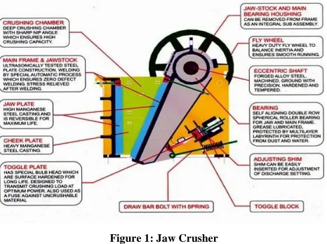
Crushers are commonly classified by the degree to which they fragment the starting material with primary and secondary crushers handling coarse materials and tertiary and quaternary crushers reducing ore particles to finer gradations. A jaw or toggle crusher consists of a set of vertical jaws, one jaw being fixed and the other being moved back and forth relative to it by a cam or pitman mechanism. The jaws are attached apart at the top than at the bottom, forming a tapered chute so that the material is crushed to smaller size as it travels downward till it escapes from the opening at bottom. The movement of the jaw can be quite small, since complete crushing is not performed in one stroke. The inertia required to crush the material is provided by a weighted flywheel that moves a shaft creating an eccentric motion that causes the closing of the gap. Jaw crusher functions and parts shown in figure 1. [5]
II. FUNCTIONS OF THE PLANT
The utilities department provides a support function to the entire plant and comprises of many departments such as auto shop, foundry, carpentry and painting, refractory, transport, electrical repair, bath crushing plant etc.
[image:1.612.327.560.434.608.2]This department provides flexible, cost economy and timely services to the alumina plant, boiler and co-generation, fabrication plant, and reduction plant. The major services are supply of water, painting jobs, metal casting, machining and repairing jobs, motor repairing, raw material unloading and bath crushing etc. to the entire plant. The smelter has a by-product as loose bath being generated in lumps and these lumps / chunks are brought to bath crushing plant via dumpers from smelter plant. The crushing plant has jaw crusher, which reduces size of bath from 5‖ to 1‖. The big size chunks above 5‖ are first broken manually to smaller pieces up to 5‖ and then fed to jaw crusher, around 250 MT of loose bath is crushed per day [1, 5, 6, 11].
Figure 1: Jaw Crusher
III. SPECIFICATIONS OF JAW CRUSHER
International Journal of Emerging Technology and Advanced Engineering
Website: www.ijetae.com (ISSN 2250-2459, Volume 2, Issue 10, October 2012)404 The equipment Specification is given below:
Capacity = 8 TPH, RPM = 300, Input Size = 6‖, Output Size = 1‖, Motor = 25 HP
Since the installation of this equipment, chronic problem of breakage of supporting bearing had been observed. The detail of Breakdown is shown in the (Figure 2).
The replacement of supporting bearing was very time consuming process and involved a lot of resources deployment, which used to take around 32 Hrs to restart the machine [9]. 34 32 35 36 32 30
32 32 32
30 32 34 32 25 27 29 31 33 35 37 39 7 /1 /11 1 8 /1 /11 2 /2 /11 1 7 /2 /11 2 /3 /11 1 9 /3 /11 3 /4 /11 1 8 /4 /11 1 /5 /11 1 7 /5 /11 5 /6 /11 1 9 /6 /11 5 /7 /11 B/D DATE B/D HOUR S
Data of Bearing Failure
[image:2.612.323.573.356.585.2]Avg. B/D frequency is 14 days & Repair Time is 32 Hrs.
Figure 2: Bar chart of bearing failure
IV. ANALYSIS OF BREAKDOWN DATA
The data of last six month was analyzed and found that the frequency of breakage of bearings is once in a fortnight and it was taking around 32 hrs to replace the bearing. As it has been mentioned earlier that 100% availability of the crusher was need and demand of the smelter plant for continuous operation of aluminum production, hence team members selected this project to be taken on priority to find the solution.
A. Need to Reduce Down Time of Jaw Crusher
Customer requirement was not fulfilled on time. The cost incurred for Spares i.e. bearings (Rs 49,540 / breakdown) was very high. Around 85% of the maintenance cost incurred in the maintenance of crusher. Dependency with other departments for arrangement of truck, hydra and cranes for crankshaft dismantling and assembly, was a perennial problem and thus challenging. Even after lot of valuable resources like energy and manpower was being consumed in this process, our main aim of customer satisfaction was not being fulfilled.
B. Problem Detail and Analysis
When the Supporting Bearing fails following Major steps needed to be taken for bearing replacement.
Dismantling of crank shaft assembly from main crusher body.
Shifting of crankshaft assembly to workshop (1 KM away from job site) for dismantling and refitting of pulley, fly wheel and bearings etc, as these was press fitted. Hydraulic Press for removal and fittings. Reshifting of crank shaft assembly to crusher area
(fitted with new bearing).
Crank shaft assembly mounting on crusher, inspection and trial and handing over to operation.
C. Tool and Techniques used for Problem Solving
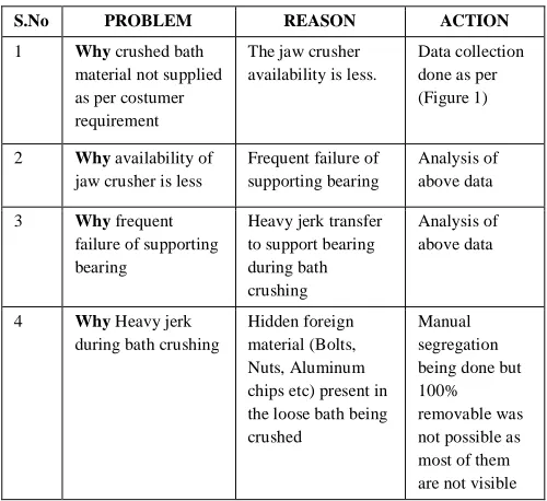
The problem is solved using following steps: Why-Why Analysis: This tool was used to find out
the root cause of problem by asking question (Why).
TABLEI
WHY-WHY ANALYSIS FOR PROBLEM IDENTIFICATION
S.No PROBLEM REASON ACTION
1 Why crushed bath material not supplied as per costumer requirement
The jaw crusher availability is less.
Data collection done as per (Figure 1)
2 Why availability of jaw crusher is less
Frequent failure of supporting bearing
Analysis of above data
3 Why frequent failure of supporting bearing
Heavy jerk transfer to support bearing during bath crushing
Analysis of above data
4 Why Heavy jerk during bath crushing
Hidden foreign material (Bolts, Nuts, Aluminum chips etc) present in the loose bath being crushed
Manual segregation being done but 100% removable was not possible as most of them are not visible
Brain Storming: Brainstorming is an excellent way of developing many creative alternate solutions to a problem. It is designed to break out of thinking patterns into new way of looking at things.
Many ideas generated in Brainstorming session were simultaneously argued, analyzed and evaluated.
International Journal of Emerging Technology and Advanced Engineering
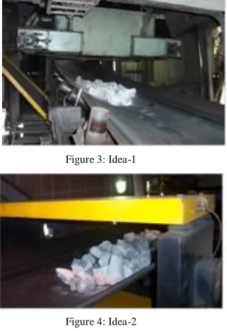
Website: www.ijetae.com (ISSN 2250-2459, Volume 2, Issue 10, October 2012)405 Analysis:-It could segregate only the ferrous material however most of non-ferrous material could not be separated out.
Action: - In our case 80% of foreign material is non ferrous (Aluminum) so the idea did not seem to be feasible. This idea was dropped and led to further discussion.
Idea-2: - Metal detector shown in Fig 4 to be provided for segregation of ferrous as well as non-ferrous materials Analysis: - It will detect all foreign materials including Aluminum chips, which will trip the belt to take out the detected foreign material. It was impossible to find out in which chunk of Bath the foreign material is present and will delay the Crushing processing.
Action: - This idea was also not found feasible.
Idea-3: - As the above 2 ideas could not work for elimination of bearing failure problem it was decided to minimize the repairing time for Bearing replacement. Analysis: -Though this was a short term solution but was the only way out at that time. By reducing the repairing time at least the productivity would amplify.
[image:3.612.95.259.425.664.2]Action: - According a detailed process mapping was carried out for the existing procedure of bearing replacement [10, 11, 12].
Figure 3: Idea-1
Figure 4: Idea-2
Process Mapping: Methods used to identify potential Improvement; the process mapping gives us various opportunities for improvement (NVA elimination).
This process mapping as the existing activities were broken into three stages:
(A) Dismantling activity at Crusher Area (B) Activity at workshop
(C) Final assembly at Crusher Area as detailed below [7, 10, 12].
TABLE II
PROCESS MAPPING FOR BEARING REPLACEMENT OF CRANK SHAFT
S.no Job Description Before
in hrs. VA/ NVA
A Activity at Crusher Area for Dismantling
1 Dismantling of crusher for taken out the Crank Shaft Assembly
2 NVA
2 Arrangement of Hydra and Truck for transportation to Workshop
4 NVA
3 Shifting of crankshaft assembly to workshop (1 KM away from job site)
2 NVA
B Activity at Workshop for Dismantling and Assembly
1 Crankshaft assembly unloading by E.O.T. crane
1 NVA
2 Dismantling of Fly wheel and pulley through Press
3 NVA
3 Dismantling of Bearing 2 VA
4 Cleaning of bearing housing and crank shaft 2 VA
5 Straightness checking of crank shaft 2 VA
6 Replacement of Roller bearing 2 VA
7 Fitting of Pulley and Fly wheel by press 2 NVA
8 Arrangement of Hydra and Truck for transportation to crusher area
4 NVA
9 Shifting of crankshaft assembly from workshop to Jaw crusher for fitting
2 NVA
C Activity at Crusher Area for Assembly
1 Assembly of crank shaft 2 VA
2 Assembly of Jaw crusher and trial 2 NVA
International Journal of Emerging Technology and Advanced Engineering
Website: www.ijetae.com (ISSN 2250-2459, Volume 2, Issue 10, October 2012)406 Pie Chart: It represents relative proportion of different
attribute in visual form.
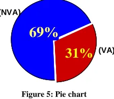
The outcome of this exercise was very fruitful.
Out of the total 32 hours of repairing time around 22 hours was a Non Value Adding activity and 10 hrs were Value Adding activity. The major contribution of NVA due to Shifting of crankshaft assembly to workshop which was taking 13 hrs (40% of total repair time).The dismantling and assembly were taking 11 hrs.
(34% of total repair time) and bearing replacement was taking 8 hrs. So we decided to reduce/ eliminate the shifting activity, for this we again had a brainstorming session to address this issue [10, 12].
69%
31%
69%
69%
[image:4.612.115.227.302.399.2]31%
31%
Figure 5: Pie chart
The brainstorming session and why - Why analysis was conducted to find out solution for eliminating the NVA and thereby reducing the MTTR as detailed below:
TABLEIII
WHY-WHY ANALYSIS FOR EVALUATION
S.No PROBLEM REASON ACTION
1 Why Repair time (MTTR) is very high?
Complete crankshaft assembly with flywheel and pulley shifted to central workshop for bearing replacement?
Review of data
2 Why Complete assembly shifted to Central Workshop for bearing replacement
There is no facility for dismantling of Press fitted Flywheel, Pulley and Bearing at job site
Review of data
3 Why
Dismantling of Flywheel and Pulley required?
Pulley and Flywheel is fitted at both side of crankshaft. For bearing replacement first we need to dismantled Pulley and Flywheel
Brainstorming done for different procedure of bearing replacement at job site.
Why- Why Analysis and brainstorming analysis gave us a direction to look for different procedure for bearing replacement. So following alternate was generated during discussion and analyzed the same.
Alternate-1: - To install Hydraulic press and EOT Crane for dismantling of the flywheel and pulley at job site
Analysis: -The cost of procurement and installation of Hydraulic Press and EOT crane was very high and not economical for single job
Action: -The alternate 1 was not feasible
Alternate-2: -As the roller Bearings are circular and can be replaced only after removing the flywheel and pulley. So an alternative of bearing was thought which could be replaced without removal of flywheel and pulley.
Analysis: - As in crankshaft of engines the Bearing are in two halves same can be used and replaced at site thereby eliminating major NVA of dismantling and assembly of crank shaft.
Action: -Then the team further built up on the idea with lot of thought process among the members and arrived at decision to use Bush/Babbited bearing in two halves.
PDCA Cycle: This is a structured approach for effectively implementation of project.
PLAN
The improvement initiative was executed with the help of PDCA cycle. The planning phase was divided in five parts: (i) Dimension selection of bearing
(ii) Material selection of bearing (iii) Material planning
(iv)Arrangement for lubrication of Bearing (v) Arrangement for Mono Rail and Chain block
C.I. Bearing housing
White metal bush bearing
NEW DESIGNED TWO HALF BUSH BEARING
Figure 6: Bearing Design
(NVA)
International Journal of Emerging Technology and Advanced Engineering
Website: www.ijetae.com (ISSN 2250-2459, Volume 2, Issue 10, October 2012)407
Dimension selection of bearing
Developed a sketch (As shown in figure 6) of two halves bearing as per diagram1 and consulted Design department for further designing and drawing to suit the desired application, which was finally approved with two halves babbited bearing.
Material selection of bearing
The R&D Department suggested the appropriate material composition to be used for outer body carbon steel casting grade 230-450 W as per IS-1030 and for inner bush babbit metal lead tin base bearing alloy Sn-75%, Sb-12%, Pb-9.3 –10.7% (max) Cu-3%, Fe-0.08%(max) AS -0.15%(max)
Material Planning
On the approval from design department it was planned to get casting done from our foundry shop as per approved material composition and size.
Arrangement for lubrication of bearing:
Another major task was to provide continous lubrication to bush bearing. We designed the tank drawing was made which was to be provided at the location.
Arrangement of mono rail and chain block
For replacement of bearing the crankshaft had to be lifted. It was planned for making arrangement of monorail and chain block. The design department was consulted for the size of chain block and location for installation of monorail.
DO
After receiving of casting following actions were taken: Casting and machining of bush bearing: Casting received from Foundry Shop was sent to machine shop for final machining as shown in fig 7 and 8.
[image:5.612.337.548.252.358.2]Figure 7: Casting of Bush Bearing
Figure 8: Machining of Bush Bearing
Arrangement for lubrication of bearing: A ¾‖ BSP tapped hole was provided in the housing for grease to pass into the bearing. Two numbers of fabricated lubrication tanks were fitted at either side of housing of crank shaft as shown in Fig 9.
Installation of mono rail and chain block: A spare chain block at our workshop which was lying idle due to dismantling of a machine so we used the monorail and installed at our shed (Shown in Fig 10)
Figure 9: Monorail Figure 10: Sprak Chain Block
[image:5.612.109.227.530.696.2]Process of bearing replacement: Before modification initially 2 numbers of roller bearing part number 22326 (Figure 11) was fitted on both sides of crank shaft and then the fly wheel and pulley were used to be fited on both ends. After implementation the bush bearing is being replaced by lifting the crank shaft assembly with the help of chain block at job site. Upper half top cover with 4 nos Bolts are removed after crankshaft assembly is lifted up by chain block provided and the lower half is also removed. Then new lower bush bearing is placed at the location and crank shaft assembly is lowered down with the help of chain block and new top bush bearing is placed and finally top cover being provided and all bolts are tighted. Finally toggle plate, V belt, all other accessories, guard etc are provided and trial is taken and handed over to operation.
[image:5.612.395.490.536.622.2]Crank Shaft Crank Shaft Crank Shaft
Figure 11: Bearing
CHECK
International Journal of Emerging Technology and Advanced Engineering
Website: www.ijetae.com (ISSN 2250-2459, Volume 2, Issue 10, October 2012)408 Firstly a rise in temperature was observed. The bearing was dismantled and we found that the Lubrication was not appropriate on the sides. Hence an additional groove was provided in the bearing. Lubrication tank was also modified and two points were provided at each bearing for proper Lubrication.
Secondly high vibration was observed in the 4th week. On dismantling a scratch was observed on the crankshaft. On discussion with R&D the material of bearing was changed from lead base to tin base bearing alloy ―ASTM-B-23 Alloy 2‖
ACT
To avoid any further damage on the crankshaft developed check sheets and made a schedule was developed. A Monthly Schedule was made for Preventive Maintenance, Supporting Bearing Replacement and Vibration Analysis [2, 3, 4, 8, and 10].
V. PROCESS MAPPING
S.No Job Description Before
in Hrs. After in Hrs.
VA/ NVA
A Activity at Crusher Area for dismantling
1 Dismantling of crusher for taken out the Crank Shaft Assembly
2 ½ NVA
2 Arrangement of Hydra and Truck for transportation to Workshop
4 0 NVA
3 Shifting of crankshaft assembly to workshop(1 KM away from job site)
2 0 NVA
B Activity at Workshop
1 Crankshaft assembly unloading by E.O.T. crane
1 0 NVA
2 Dismantling of Fly wheel and pulley through Press
3 0 NVA
3 Dismantling of Bearing (now this activity done at Crusher area)
2 1 (i) V
A
4 Cleaning of bearing housing and crank shaft (now this activity done at Crusher area)
2 ½ VA
5 Straightness checking of crank shaft
2 0 VA
6 Replacement of Roller bearing (now this activity done at Crusher area)
2 ½ VA
7 Fitting of Pulley and Fly wheel by press
2 0 NVA
8 Arrangement of Hydra and Truck for transportation to crusher area
4 0 NVA
9 Shifting of crankshaft assembly from workshop to Jaw crusher for fitting
2 0 NVA
C Activity at Crusher Area for assembly
1 Assembly of crank shaft 2 ½ (ii) V
A
2 Assembly of Jaw crusher and trial
2 ½ (iii) N
V A
TOTAL 32 3 ½
After modification the activity S.No B (1, 2, 5, 7, 8 and 9) eliminated and B (3, 4 and 6) done at Job site in 2 hrs instead of 6 hrs.
The analysis of Process mapping revealed that most of NVAs have been eliminated and VAs has also been reduced to 2.5 hrs from10.hrs. And now the replacement of Bush Bearing is being done at job site during ―Time Based Preventive Maintenance [13].
VI. RESULTS Tangible Gains
S. no Description UOM Before After
1 Break Downs Per
Month No 02 NIL
2 Down Time ( Per
Break Down) Hours 32 3.5
3 Manpower Cost Rs. 3840 420
4 Materials / Spares
Cost Rs. 49,540/ 14,230/
5 Operating cost of
Press Machine Rs. 300
00.00
6 Transportation Cost Rs. 840 00.00
7
Total Replacement Cost per Set ( 3+4+5+6)
Rs 54, 520/- 14, 650/-
8 Total Replacement
Cost per Month Rs.
54520 X 2 = 1,09,040/-
14650 X 1 = 14,650/-
9 Saving Per Month Rs. 109040 –14650 = 94,390/-
International Journal of Emerging Technology and Advanced Engineering
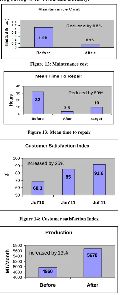
Website: www.ijetae.com (ISSN 2250-2459, Volume 2, Issue 10, October 2012) [image:7.612.69.272.212.705.2]409 As it is evident from the above table that before modification, the Monthly breakdowns used to be 2 in No and Total Down Time was of 64 hrs per month, which has been reduced to zero and 3 ½ hrs. Also this 3 ½ hrs are not Breakdown Maintenance Hrs but it is being consumed for Time Based Preventive Maintenance. This has led to a recurring saving of Rs 11.32 Lac annually.
Figure 12: Maintenance cost
Mean Time To Repair
32
3.5
10
0 10 20 30 40
Before After target
H
o
u
rs Reduced by 89%
Figure 13: Mean time to repair
Figure 14: Customer satisfaction Index
Production
5678
4960
4600 4800 5000 5200 5400 5600 5800
Before After
M
T
/M
o
n
th Increased by 13%
Figure 15: Production
Intangible Gains
1. Improved maintenance and project implementation skill of team members
2. Uninterrupted supply of bath to Smelter Plant 3. High satisfaction of Customer
4. On Time In Full Delivery (OTIF)
VII. CONCLUSION
The Customer requirement of Crushed Bath has been fulfilled by increasing the availability by 17%, Eliminating Breakdown, Reducing the MTTR by 89% and Maintenance Cost by 86% of Jaw Crusher. The study is helpful for gaining improvement in similar field as well as also in others.
ACKNOWLEDGEMENT
The authors would like to acknowledge Mr. R. K. Gupta, Manager (WCM, Hindalco Industries Ltd, Renukoot, UP, India) for his support in providing the valuable information.
REFERENCES
[1] Shrivastava, A. K., and Sharma, A. K. 2012, ―A Review on Study of Jaw Crusher‖, International Journal of Modern Engineering Research, Vol. 2, Issue 3, pp 885-888.
[2] Moen, R., and Norman, C., 2009, ―Evolution of the PDCA cycle‖. API. Publications, pp. 5–9.
[3] Doulah, A.B.M.S.,. Islam M.I, and Farzana I., 2012,‖ Improve The Quality Of Products In Woven Apparel Industries By Plan-Do-Check-Act (PDCA) Cycle‖, Journal of Innovation & Development Strategy, vol.6, Issue 1, pp 49-53.
[4] Castro A.D.J.D; Pinheiro A., and Ginoris Y.P., 2011, ―Application of the PDCA problem-solving method in treatment of wastewater from poultry processing‖, An Interdisciplinary Journal of Applied Science, pp 231-238.
[5] Jaw crusher<,http://en.wikipedia.org/wiki/Jaw_crusher#Jaw_crusher> accessed on 5 august, 2011
[6] Bheda R, Narag A.S., and Singla M.L., 2003, ―Apparel manufacturing a strategy for productivity improvement‖, Journal of Fashion Marketing and Management, Vol. 7, No. 1, pp 12-22.
[7] Bisen, V., and Srivastava S., 2009, ―Production and Operation Management‖, Lucknow, India Global Media, p. 175.
[8] Carr H., 1988, Technology of Clothing Manufacture, Blackwell Science Inc, ISBN 978-06320.
[9] Charles H.D., 1981, ―Point load deformation relationships and design of jaw crusher plates‖ Department of Civil Engineering. Northwestern University. Evanston., IL (U.S.A.)
[10]Corwin J., Puckett R. 2009, ―Japan’s manufacturing competitiveness strategy: challenges for Japan, opportunities for the United States‖, US Department of Commerce, International Trade Administration.
[11]Country profiler, 2011, Country Report, Malta, global edition.
[12]Danneels E., 2008, ―Organizational antecedents of second order competencies‖, Strategic Management Journal, Vol. 29, pp 519–543 .
Customer Satisfaction Index
68.3
85 91.6
50 60 70 80 90 100
Jul'10 Jan'11 Jul'11 %
International Journal of Emerging Technology and Advanced Engineering
Website: www.ijetae.com (ISSN 2250-2459, Volume 2, Issue 10, October 2012)410