http://www.scirp.org/journal/ijcns ISSN Online: 1913-3723 ISSN Print: 1913-3715
Fixed Point Iteration Chaos Controlled ZCDPLL
Qassim Nasir
Electrical and Computer Engineering Department, University of Sharjah, Sharjah, UAE
Abstract
The stable operation of first and second order Zero Crossing Digital Phase Locked Loop (ZCDPLL) is extended by using a Fixed Point Iteration (FPI) method with re-laxation. The non-linear components of ZCDPLL such as sampler phase detector and Digital Controlled Oscillator (DCO) lead to unstable and chaotic operation when the filter gains are high. FPI will be used to stabilize the chaotic operation and conse-quently extend the lock range of the loop. The proposed stabilized loop can work in higher filter gains which are needed for faster signal acquisition.
Keywords
Non-Uniform Sampling, Digital Phase Locked Loops, Zero Crossing DPLL, Chaos Control
1. Introduction
Digital Phase Locked Loop (PLL) has been widely used and for many years in wireless and wired communications subsystems. It is an essential component in clock and car-rier recovery, and frequency synthesizer. Digital Phase locked Loops (DPLLs) have bet-ter reliability and higher stability compared to analogue counbet-terpart at lower cost and can easily be part of a digital processing equipment [1]. The researchers show strong interest in the design of digital PLLs (DPLLs) to solve problems associated with analog DPLLS, such as, sensitivity to DC drift and component inaccuracies and saturation, and their need for initial calibration [1][2]. The sampler type classifies DPLL into two ma-jor categories: uniform sampling DPLLs (US-DPLLs) and non-uniform sampling DPLLs (NUS-DPLLs). Different types of NUS-DPLLs have been introduced according to the way to detect the phase difference between locally generated carrier and the input signal to the loop from the sampled signal such as zero crossing DPLL (ZCDPLL) [3] [4] and digital tan-lock loop (DTLL) [5][6][7]. ZCDPLL is a closed loop system used to follow the zero crossing of the input carrier signal. It consists of a sampler (acting as How to cite this paper: Nasir, Q. (2016)
Fixed Point Iteration Chaos Controlled ZCDPLL. Int. J. Communications, Network and System Sciences, 9, 535-544.
http://dx.doi.org/10.4236/ijcns.2016.911042
Received: September 26, 2016 Accepted: November 21, 2016 Published: November 24, 2016
Copyright © 2016 by author and Scientific Research Publishing Inc. This work is licensed under the Creative Commons Attribution International License (CC BY 4.0).
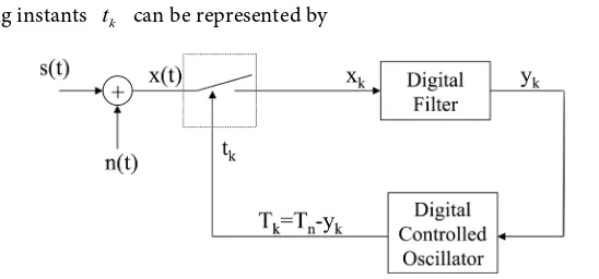
a phase detector), a digital loop filter and a digital controlled oscillator [8][9][10][11]. The most commonly used DPLL is the Zero Crossing Digital Phase Locked Loop (ZCDPLL). The operation is based on tracking the signal input phase by using non uniform sampling techniques. The sample value is a function of the signal input phase. These values are filtered before they are used back to control the next sampling time by the help of Digital Controlled Oscillator (DCO). The non-linear behaviour of ZCDPLL leads bifurcation instabilities to its path to chaos [12].
A number of methods were proposed for chaos control [13] such as using Pyragas method to broaden the tracking range by extending the stable operation behaviour of ZCDPLL to a larger digital filter gain, which leads to larger input frequency [11]. Fixed Point Iteration (FPI) with relaxation will be presented to extend the stable operation range of both first and second order ZCDPLL. The stabilized loops are analyzed and the results are verified using bifurcation theory and a numerical simulation. It is the first time that FPI used to stabilize the chaotic operation of the DPLL.
In Section 2, the conventional first order ZCDPLL operation is described. Section 3 discusses the Fixed Point stabilization algorithm, and in section 4 the second order ZCDPLL is presented, while Section 5 details the operation of the second order ZCDPLL when FPI chaos control is included in the loop. Simulation results are pre-sented in Section 6 and finally conclusions are given in Section 7.
2. First Order ZCDPLL
Conventional first order ZCDPLL is shown in Figure 1. Let us assume that the input signal x t
( )
is defined as( )
sin( ) ( )
n , 0x t =A ω t +n t t<
( )
sin(
0) ( )
, 0x t = A ω φt+ +n t t> (1)
where n t
( )
is Additive White Gaussian Noise (AWGN), φ0 is initial phase (can beassume zero without loosing generality),
ω
is the input signal frequency, and ωn isthe nominal frequency or DCO free running frequency when no input signal is applied. The input signal is assumed to be noise free [n t
( )
=0]. This input signal xk is sam-pled at tk instants determined by DCO.(
)
sin
k k k
x =A ω t (2)
[image:2.595.240.514.563.691.2]the sampling instants tk can be represented by
1
k k k
t =t − +T
(3)
k
T is the Digital Controlled Oscillator (DCO) period, which is given by [15]:
1
k n k
T =T −y− (4)
where Tn=
(
2πωn)
is the nominal period, yk−1 is the output of digital filter. Theinput signal phase can be represented as θk. The sampled signal input x t
( )
will be1
0
sin
k
k n n i k
i
x A
ω
kT yθ
−
=
= − +
∑
. (5) The phase error φk is determined by:1
0
k
k k n n i
i
kT y
φ
θ ω
−=
= − −
∑
. (6) Then1 1 1
k k k k nyk
φ φ− − =θ θ− − −ω − .
(7)
The sampled values xk is passed through a digital filter D(z) to produce the output
k
y . The digital loop filter can be of zero order (just gain block) or first order (gain and summation blocks). The loop filter output yk can be written as:
k k
y =Kx
where K is the zero order filter gain (First Order ZCDPLL), while for first order filter or second order ZCDPLL, the outputs will be:
1
1 2
0
k
k k i
i
y K x K x
−
=
= +
∑
(8)
where K1 and K2 are the loop filter gains. If a frequency step of a value ws is
ap-plied to the ZCDPLL (ws = −w wn), then the signal input phase can be expressed as:
(
)
k n tk
θ = ω ω−
(
)
1 1
k n tk
θ− = ω ω− −
(
)(
)
1 1
k k s tk tk
θ −θ − = ω ω− − −
(
)(
)
1 1
k k n Tn yk
θ −θ − = ω ω− − −
(
)
1 1
k k sn n yk
θ −θ − =ω − ω ω− − (9)
where ωsn =
(
ω ω− n)
Tn is normalized frequency step size. Consequently the phase error can be written as(
)
1 1 1
k k sn n yk nyk
φ =φ− −ω − ω ω− − −ω −
1 1
k k yk sn
φ =φ− − −ω − +ω . (10)
Therefore first order ZCDPLL phase error operation function will be:
(
)
1 sin 1
k k KA k sn
φ =φ − − φ− +ω . (11)
(
k 1)
k 1 sin(
k 1)
snf φ− =φ− −KA φ− +ω . (12)
3. Extending the Stable Operation of First Order ZCDPLL
Various methods and techniques were used to control the instability of chaotic opera-tion of control loop such as Ott-Grebogi-Yorke (OGY) or Pyragas [14]. In this paper the Fixed Point Iteration (FPI) with relaxation is used to extend the stable operation of the ZCDPLL. FPI was used the first time by Babylonian (2000 B.C) to estimate the square root. The original version was used for finding a as:
( )
1
1 2
k k n
k
a
z z f z
z
+
= + =
.
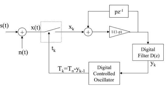
(13) Then Hillam [16] proposed FPI with relaxation for fixed point stability as follow:
( )
1
1
n n
k
f z pz
z
p
+
− =
− (14)
p is fractional constant which control the amount of feedback. This algorithm can’t be used when
( )
*1
f′ z = (non-hyperbolic fixed points (8, 9). Let us apply the above FPI with relaxation to stabilize ZCDPLL operation. Then the operation Equation (12) should become as:
( )
1 11 k k k f p p φ φ
φ = − − −
−
(
)
1 sin 1 1
1
k k sn k
k
KA p
p
φ φ ω φ
φ = − − − + − −
− . (15)
The system will be stable when φk′ <1. This condition of the derivative of Equation
(15) will be:
( )
1 1 1 cos 1 1 k k K p p φφ′ = − − − <
−
where K1=KA. The stable operation phase error (
*
k
φ ) was found to be at
* 1 1 sin sn k K ω
φ = −
[15]. The values of the constant (p) which can stabilize ZCDPLL op-eration is determined from Equation (16). The values are
2 2 1
1
1 .
2 sn
p< − K −ω
The stabilized first order ZCDPLL using FPI with relaxation is shown in Figure 2.
4. Second Order ZCDPLL Operation
The first order filter transfer function D z
( )
of the second order ZCDPLL can bewritten as:
( )
2( )
( )
1 1 .
1
Y z K
D z K
X z z−
= + =
Figure 2. FPI chaos controlled first order ZCDPLL.
Then Y z
( )
is expressed as( )
( ) ( )
( )
21 1
1 K
Y z X z D z X z K
z−
= = +
−
(16)
( )
(
1)
(
(
1)
)
( )
1 2
1 1
Y z −z− = K −z− +K X z . (17)
To express Equation (16) in time domain:
(
)
1 1 2 1 1
= .
k k k k
y y− + K +K x −K x −
Then the operation Equations (10) is given by [17]
(
)
1 2 2 1
2
k k k yk yk
φ − φ− +φ − =ω − − −
(18)
(
)
(
)
(
)
(
)
1 2 1 2 1 1 2
2 sin sin .
k k k K K k K k
φ − φ − +φ− = −ω + φ− − φ− (19)
If we assume 2 1
1 K r
K
= + , K1′ =K1ω, then the second order ZCDPLL operation
equ-ation can be written as
( )
(
)
1 1sin 1 2 1sin 2 .
k k rK k k K k
φ
=φ
− − ′φ
− −φ
− − ′φ
− (20)To guarantee the stable operation of the loop, then inequality should be satisfied [17]
1
4
0 , 1.
1
K r
r
′
< < >
+
(21)
5. Extending the Stable Operation of Second Order ZCDPLL
The proposed FPI with relaxation for fixed point stability is applied for second order as well and the new operation equation can be written as:
(
)
(
)
(
1 1 1 2 1 2 1)
1
= sin sin .
1
k k rK k k K k p k
p
φ − φ− − ′ φ− −φ− − ′ φ− − φ− (22)
The system state vector is defined as 1 2
k k
z =φ − , 2
1
k k
z =φ− , z=
(
z z1, 2)
T. Then( )
( )
(
)
( )
( )
( )
2 1 1 12 2 1 1 2
2 2 1 1 1 1 sin sin 1 k k k
k k k k k
k
z
g z
g
z rK z z K z pz
z p + + = − ′ − − ′ − − z G z
around the stable operating point
( )
1 1sin zk ≈zk ,
( )
2 2
sin zk ≈zk . The Jacobian
( )
ji
g z
′ = ∂ ∂
G z is given by
( )
(
)
(
)
1 1 0 1 . 1 1 1 11 p K 1 p rK p
′ = ′ ′ − − − − − −
G x (24)
In order to have eigen values of G z′
( )
less than 1, or λi <1,i=1, 2, where λisatisfies the characteristic equation
( )
( )
*0
F λ = λI−G z′ = in [17]
( )
2(
)
(
)
1 1
1 1
1 1 .
1 1
F rK p K
p p
λ =λ − − ′− λ+ − ′
− − (25)
Using Jury stability test [18], the roots of the polynomial F
( )
λ defined in (25) arewithin a unit circle, or the eigen values are less than 1, if
( ) ( )
21 F 1
− − greater than 0.
Then p should satisfies the following:
(
1) (
1)
1
1 1 0
1−p −rK′−p + −K′ >
1
2−rK′− > − +p 1 p
(
)
1 3 1 . 2 K rp< − ′ +
(26)
Since 1
4 1 K
r
′ <
+ or K1′ + <
(
1 r)
4 this leads that p< −0.5. Jury stability test ap-plied on F
( )
λ the absolute value of the constant term of the equation should be lessthan 1. This leads to
(
1)
1
1 1
1−p −K′ <
(
1)
1 1 K′ 1
− < − <
1 2 .
p<K′< −p (27)
6. System Performance
The first and second order conventional and FPI chaos controlled ZCDPLL is simu-lated by using MATLAB. The input signal is assumed to be s t
( )
=sin( )
wt with peakamplitude of 1 volt and angular frequency of 2π ,f f 1 T
ω= = . The free running fre-
quency of DCO is wn =2π rps or fn =1 Hz. During simulation, the first 100 samples
of the DCO period (TDCO) values are discarded to allow the loop to stabilize. The next
100,000 samples are collected and recorded to generate bifurcation plot. The bifurca-tion plot maps the TDCO values versus the filter gain(s). It will be used to compare the
operation ranges of the conventional and FPI chaos controlled ZCDPLL.
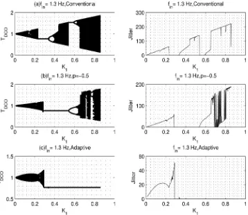
First order ZCDPLL is subjected to a frequency step of 1.3 Hz. Then TDCO values are
recorded for three cases. The first case shown in Figure 3(a) is for conventional ZCDPLL. The conventional loop bifurcates at K1 =0.32. DCO period jitter is used to
= TDCO,max TDCO,min
T
−
, where T is input signal period). Figure 3(b) shows that FPI chaos controlled first order ZCDPLL bifurcates K1 =0.53, which is higher than for
conven-tional loop (Chaos control constant p= −0.8 was used in this test). This agrees with the theoretical analysis presented earlier. Figure 3(c) shows how adaptive values of the constant (p) (Equation (16)) can be used to continuously stabilize the loop by changing its values according to filter gain (K1).
There are two filter parameters in the second order loop (K K1, 2). In these
simula-tions we fixed the gains ratio ( 2 1
1 K r
K
= + ) and vary K1 value. Figure 4 shows clearly
that the FPI chaos controlled loop has extended stable operation when the filter para-meter (K1) varied. Gains ratio used here is r=1.3, and the chaos control constant is
set to be (p= −0.8). The conventional ZCDPLL bifurcates at K1=0.25 while the FPI
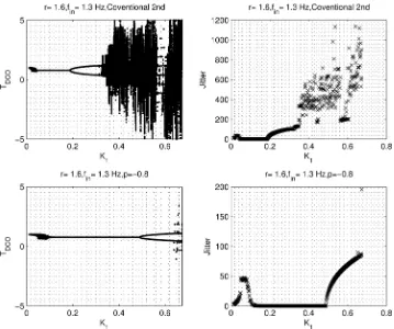
chaos controlled loop bifurcate after K1=0.6. Figure 5 shows that even the filter
gains ration (r) is increased to 1.6, that the loop still has extended operation range as well. The conventional loop bifurcates at K1=0.2, while the FPI chaos controlled loop
starts to bifurcate at K1=0.5. If the filter gains ratio r is further increased as shown in
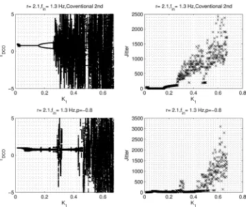
[image:7.595.199.557.378.688.2]Figure 6, the FPI chaos controlled will be unstable. This means that the chaos control constant (p) should be carefully chosen according to the inequality that is derived in this paper.
Figure 4. Second order FPI-ZCDPLL performance for different values of p and r=1.1.
[image:8.595.195.554.389.689.2]Figure 6. Second order FPI-ZCDPLL performance for different values of p and r=2.1.
7. Conclusion
This paper proposes a Fixed Point Iteration (FPI) with relaxation to control the chaotic operation of the ZCDPLL. The analytic expressions for the stable operation for both conventional and FPI chaos control first and second order ZCPLL are found and con-firmed by simulation. It is found that the lock range of the FPI chaos controlled loop is larger than that of the conventional loop for both orders. The validity of the results is conformed through numerical simulations. It is also found that careful selection of chaos control parameters is needed to ensure that the loop is still working in stable op-eration. This extended operation of the ZCDPLL leads to larger lock range. The larger values of filter gains of FPI chaos controlled will automatically decrease the input signal acquisition time.
References
[1] Lindsay, W. and Chie, C.M. (1981) A Survey of Digital Phase Locked Loops. IEEE Pro-ceeding, 69, 410-431. http://dx.doi.org/10.1109/PROC.1981.11986
[2] Al-Araji, S.R., Hussain, Z.M. and Al-Qutayri, M.A. (2006) Digital Phase Lock Loops: Ar-chitectures and Applications. Kluwer Academic Publishers (Springer), Netherlands. http://dx.doi.org/10.1007/978-0-387-32864-5
Perfor-mance Evaluation in Faded Mobile Channels. Circuits and Systems, 2, 139-144. http://dx.doi.org/10.4236/cs.2011.23021
[5] Lee, J. and Un, C. (1982) Performance Analysis of Digital Tanlock Loop. IEEE Transactions on Communications, 30, 2398-2411. http://dx.doi.org/10.1109/TCOM.1982.1095407 [6] Hussain, Z.M. and Boashash, B. (2002) The Time-Delay Digital Tanlock Loop: Performance
Analysis in Additive Gaussian Noise. Journal of the Franklin Institute, 339, 4360. http://dx.doi.org/10.1016/S0016-0032(01)00059-X
[7] Sarkar, B.C., De Sarkar, S.S. and Banerjee, T. (2014) Nonlinear Dynamics of a Class of Dig-ital Tan-Lock Loops with Non-Ideal Phase Detector. Signal Processing, 104, 311-318. http://dx.doi.org/10.1016/j.sigpro.2014.04.008
[8] Nasir, Q. and Al-Araji, S. (2009) Performance Analysis of Zero Crossing DPLL with Linea-rized Phase Detector. International Journal of Information and Communication Technolo-gy, 1.
[9] Al-Araji, S., Mezher, K. and Nasir, Q. (2013) First-Order Digital Phase Lock Loop with Continuous Locking. 5th International Conference on Computational Intelligence, Com-munication Systems and Networks, Madrid, 5-7 June 2013, 414-417.
http://dx.doi.org/10.1109/cicsyn.2013.30
[10] Nasir, Q. and Al-Araji, S. (2013) Performance Evaluation of Sigma Delta Zero Crossing DPLL. The IEEE International Conference on Electronics, Circuits, and Systems, 11-14 December 2011, Beirut.
[11] Nasir, Q. (2005) Extended Lock Range Zero-Crossing Digital Phase-Locked Loop with Time Delay. EURASIP Journal on Wireless Communications and Networking EURASIP JWCN, 3, 413-418. http://dx.doi.org/10.1155/wcn.2005.413
[12] Nasir, Q. (2004) Chaotic Behaviour of First Order Zero Crossing Digital Phase Locked Loop. IEEE Asia-Pacific Conference on Circuits and Systems, 977-980.
http://dx.doi.org/10.1109/apccas.2004.1413044
[13] Fradkov, A.L. and Evans, R.E. (2002) Control of Chaos: Survey 1997-2000. Proceedings of 15th IFAC World Congress, Barcelona.
http://dx.doi.org/10.3182/20020721-6-es-1901.01645
[14] Pyragas, K. (1992) Continuous Control of Chaos by Self-Controlling Feedback. Physical Letters A, 170, 412-428. http://dx.doi.org/10.1016/0375-9601(92)90745-8
[15] Osborne, H.C. (1980) Stability Analysis of an Nth Power Phase-Locked Loop-Part I: First Order DPLL. IEEE Transactions on Communications, 28, 1343-1354.
http://dx.doi.org/10.1109/TCOM.1980.1094771
[16] Hillam, B. (1975) A Generalization of Kransnoselki’s Theorem on the Real Line. Mathe-matics Magazine, 48, 167-168. http://dx.doi.org/10.2307/2689700
[17] Osborne, H.C. (1980) Stability Analysis of an Nth Power Phase-Locked Loop-Part II: Second- and Third-Order DPLLs. IEEE Transactions on Communications, 28, 1355-1364. http://dx.doi.org/10.1109/TCOM.1980.1094772
Submit or recommend next manuscript to SCIRP and we will provide best service for you:
Accepting pre-submission inquiries through Email, Facebook, LinkedIn, Twitter, etc. A wide selection of journals (inclusive of 9 subjects, more than 200 journals)
Providing 24-hour high-quality service User-friendly online submission system Fair and swift peer-review system
Efficient typesetting and proofreading procedure
Display of the result of downloads and visits, as well as the number of cited articles Maximum dissemination of your research work
Submit your manuscript at: http://papersubmission.scirp.org/